


Miele PT 8251, PT 8251 COP, PT 8253, PT 8255, PT 8257 Fitting instructions
...Produktgruppen 522, 592 |
Umbauund Montageanweisung |
1 von 30 |
M.-Nr. 07946040 |
PT 8251, PT 8251 COP, PT 8253, PT 8255, PT 8257, PT 8331, PT 8331 COP, PT 8333, PT 8335, PT 8337, UO 8250, UG 8250, UO 8330,
UG 8330 x
de |
Montageanweisung Unterbau- |
en |
Fitting instructions - Plinth |
fr |
Notice de montage de socle |
|||
sockel UO 8250 / UO 8330, |
UO 8250 / UO 8330, |
UO 8250 |
/ UO 8330, |
|||||
|
UG 8250 / UG 8330 |
|
UG 8250 / UG 8330 |
|
UG 8250 |
/ UG 8330 |
||
|
|
|
|
|
|
|||
ni |
Montage-instructie sokkel |
da |
Monteringsanvisning sokkel |
sv |
Monteringsanvisning sockel |
|||
UO 8250 |
/ UO 8330, |
UO 8250 |
/ UO 8330, |
UO 8250/UO 8330, |
||||
|
UG 8250 |
/ UG 8330 |
|
UG 8250 |
/ UG 8330 |
|
UG 8250/UG 8330 |
|
|
|
|
|
|
|
|||
it |
Set di montaggio base |
es |
Instrucciones de montaje Zócalo |
am |
Installation Instructions - |
|||
UO 8250 |
/ UO 8330, |
UO 8250 |
/ UO 8330, |
Stand UO 8250/UO 8330, |
||||
|
UG 8250 |
/ UG 8330 |
|
UG 8250 |
/ UG 8330 |
|
UG 8250/UG 8330 |
|
|
|
|
|
|
|
|
|
|
1
2
28.09.2010 |
Diese Unterlagen dürfen ohne unsere Genehmigung weder vervielfältigt noch Dritten zugänglich gemacht werden. Eigentumsrechte vorbehalten. |
Produktgruppen 522, 592 |
Umbauund Montageanweisung |
2 von 30 |
M.-Nr. 07946040 |
x
3
4
6
5
28.09.2010 |
Diese Unterlagen dürfen ohne unsere Genehmigung weder vervielfältigt noch Dritten zugänglich gemacht werden. Eigentumsrechte vorbehalten. |

Produktgruppen 522, 592 |
Umbauund Montageanweisung |
3 von 30 |
M.-Nr. 07946040 |
de
Benötigte Teile x
Anzahl |
M.-Nr. |
Benennung |
1 |
07761970 |
Montagesatz Sockel UO 8250 |
oder |
|
|
1 |
07762000 |
Montagesatz Sockel UO 8330 |
oder |
|
|
1 |
07761950 |
Montagesatz Sockel UG 8250 |
oder |
|
|
1 |
07761990 |
Montagesatz Sockel UG 8330 |
Hinweis
Diese Umbauarbeiten dürfen grundsätzlich nur von einer Elektrofachkraft (fachliche Ausbildung, Fachkenntnisse und Facherfahrungen, zeitnahe berufliche Tätigkeit) unter Berücksichtigung der gültigen Sicherheitsbestimmungen durchgeführt werden.
Für die Inbetriebnahme, Instandsetzung, Änderung, Prüfung und Wartung elektrischer Geräte sind die entsprechenden gesetzlichen Grundlagen, Unfallverhütungsvorschriften, die gültigen Normen, die der Sicherheit dienen, sowie die am Aufstellungsort gültigen Vorschriften der Energieversorgungsunternehmen zu beachten.
Hinweis
Wartungsarbeiten an Gasgeräten dürfen, außer durch das Gasversorgungsunternehmen und Vertragsinstallationsunternehmen, nur von Wartungsunternehmen ausgeführt werden, die den Festlegungen des DVGW-Arbeitsblattes G 676 entsprechen. Wartungsarbeiten an Gasgeräten dürfen grundsätzlich nur von einer Fachkraft unter Berücksichtigung der gültigen Sicherheitsbestimmungen durchgeführt werden.
Bevor Wartungsarbeiten am Gerät ausgeführt werden, ist eine Trennung vom Gasnetz unbedingt erforderlich.
Gefahr!
Auch bei ausgeschaltetem Gerät kann Netzspannung an Bauteilen anliegen!
Deshalb ist, bevor Wartungsarbeiten, Instandsetzungsarbeiten oder Änderungen am Gerät durchgeführt werden, eine sichere Netztrennung von allen aktiven, spannungsführenden Leitungen sowie anschließend eine Messung der Spannungsfreiheit erforderlich!
Grundsätzlich muss eine allgemeine Sichtprüfung und Gefährdungsbeurteilung durchgeführt werden.
Ein nicht fachgerechten Änderung kann zu einer Gefährdung führen (Brand, elektrischer Schlag usw.).
Gefahr!
Die Schutzleiterfunktion kann durch einen fehlerhaften Gehäusezusammenbau außer Kraft gesetzt werden.
Die Schutzleiterfunktion ist bei Montage der Gehäuseteile wieder herzustellen.
Elektrische Sicherheitsprüfung durchführen. (Sichtprüfung und Messung des ordnungsgemäßen Schutzleiterwiderstandes).
Gefahr!
Bei der Montage dürfen berührbare leitfähige Teile, die nicht am Schutzleiter angeschlossen sind, keine Schutzleiterverbindung haben (verstärkte, doppelte Isolierung).
Der Nachweis ist durch Messen des ordnungsgemäßen Isolationswiderstandes und Berührungsstromes nachzuweisen.
28.09.2010 |
Diese Unterlagen dürfen ohne unsere Genehmigung weder vervielfältigt noch Dritten zugänglich gemacht werden. Eigentumsrechte vorbehalten. |

Produktgruppen 522, 592 |
Umbauund Montageanweisung |
4 von 30 |
M.-Nr. 07946040 |
Gefahr!
Verletzungsgefahr bei der Montage
•Stromschlaggefahr. Vor Wartungsund Instandsetzungsarbeiten an der Maschine, alle spannungsführenden Leitungen vom Netz trennen.
•Den Sockel nur an Waschautomaten montieren, die nicht installiert sind. Deinstallation siehe Maschinen-Gebrauchsanweisung.
•Quetschgefahr. Rutschfeste Handschuhe und Sicherheitsschuhe tragen.
•Quetschgefahr. Darauf achten, dass keine Körperteile, insbesondere Hände und Füße, unter oder zwischen die Maschinen gelangen.
•Unfallgefahr. Sicherstellen, dass während der Montagearbeiten keine Personen oder Tiere in den Arbeitsbereich gelangen können.
•Verletzungsgefahr, insbesondere Verletzung der Wirbelsäule. Das Gewicht der Maschine im Verhältnis zur eigenen körperlichen Kraft beachten. Gewichtsangabe der Maschine siehe Maschinen-Gebrauchsanweisung.
Kippgefahr. Verletzungsgefahr durch fehlerhafte Montage
•Die Maschinen stets mit dem Sockel verschrauben.
•Bei Einzelaufstellung den Sockel mit dem Zubehör Fundamentbefestigung M.-Nr. 01497252 auf dem Fußboden befestigen. Im Umbausatz enthalten.
•Bei der Bodenbefestigung vier Sockelfüße am Boden befestigen.
Hinweis
Den Sockel ausschließlich für folgende Miele-Geräte verwenden:
•UO 8250 / UG 8250 = PT 8251, PT 8251 COP, PT 8253, PT 8255, PT 8257 UO 8330 / UG 8330 = PT 8331, PT 8331 COP, PT 8333, PT 8335, PT 8337
Hinweis
Erforderliches Werkzeug:
•Wasserwaage zum lotrechten und waagerechten Ausrichten des Sockels
•1 x Bohrmaschine
•1 x Bohrer Ø 12 mm
•1 x Maulschlüssel Schlüsselweite 13 mm für Mutter M8
•2 x Maulschlüssel Schlüsselweite 10 mm für Mutter M6
•1 x Schraubendreher Torx 20
Hinweis
Der Montagesatz Sockel UO 8250 M.-Nr. 07761970 oder der Montagesatz Sockel UO 8330 M.-Nr. 07762000 bestehen aus:
•1 x Sockel UO 8250 oder 1 Sockel UO 8330
•1 x Zubehör Fundamentbefestigung mit Schachtel: 4 x Spannlasche / 8 x Scheibe verzinkt B6,4 / 4 x Sechskantschraube M6 x 20 / 4 x Sechskantmutter M6 / 4 x Dübel S12 / 4 x Scheibe 8,4 / 4 x Sechskant-Holzschraube 8 x 65 / 20 x Unterlegblech / 8 x Scheibe 38 mm Ø
•1 x Zubehör Begleitschriften mit dieser Montageanweisung und Inbetriebnahmekarte. Diese Umbauund Montageanweisung heißt “Montageanweisung Unterbausockel UO 8250 / UO 8330, UG 8250 / UG 8330”.
Hinweis
Der Montagesatz Sockel UG 8250 M.-Nr.07761950 oder der Montagesatz Sockel UG 8330 M.-Nr. 07761990 bestehen aus:
•1 x Sockel UO 8250 oder 1 Sockel UO 8330, 1 x Vorderwand, 2 x Seitenwand, 8 x Linsenschraube 4,8 x 9,5 und 4 x Gummipuffer, beim Montagesatz Sockel UG 8250 M.-Nr. 07761950
•1 x Zubehör Fundamentbefestigung mit Schachtel: 4 x Spannlasche / 8 x Scheibe verzinkt B6,4 / 4 x Sechskantschraube M6 x 20 / 4 x Sechskantmutter M6 / 4 x Dübel S12 / 4 x Scheibe 8,4 / 4 x Sechskant-Holzschraube 8 x 65 / 20 x Unterlegblech / 8 x Scheibe 38 mm Ø
•1 x Zubehör Begleitschriften mit dieser Montageanweisung und Inbetriebnahmekarte. Diese Umbauund Montageanweisung heißt “Montageanweisung Unterbausockel UO 8250 / UO 8330, UG 8250 / UG 8330”.
Liste der Abbildungen:
–Abb. 1, Sockelhöhe
–Abb. 2, Bohrungen Bodenbefestigung
–Abb. 3, Bohrungsmaß Bodenbefestigung
–Abb. 4, Montage Bodenbefestigung
28.09.2010 |
Diese Unterlagen dürfen ohne unsere Genehmigung weder vervielfältigt noch Dritten zugänglich gemacht werden. Eigentumsrechte vorbehalten. |

Produktgruppen 522, 592 |
Umbauund Montageanweisung |
5 von 30 |
M.-Nr. 07946040 |
–Abb. 5, Montage Spannlasche
–Abb. 6, Sockel UG 8250 / UG 8330
x
Kürzel |
Erklärung |
|
|
UM |
Unterbau Miele, Sockel |
|
|
B |
Bodenbefestigung |
|
|
Tabelle 1: Legende Abkürzungen
–Gegebenenfalls den Gasanschluss schließen.
–Die Maschine vom bestimmungsgemäßen Elektroanschluss und gegebenenfalls vom Gasnetz trennen und gegen Wiedereinschalten sichern.
–Sockel positionieren und die Bohrlöcher anzeichnen, siehe Abb. 2, Pos. 1.
x
Hinweis
Mindestabstände aus dem Installationsplan beachten.
Seitlicher Wandabstand der Maschine mindestens 10 mm.
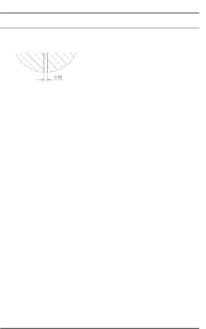
–4 Bohrungen mit 12 mm Ø ca. 65 mm tief in den Fußboden einbringen, siehe Abb. 3.
–4 Dübel S12 bündig in die Bohrungen schieben, siehe Abb. 4, Pos. 1.
–Mit Unterlegblechen (Abb. 4, Pos. 2) und Wasserwaage den Sockel lotrecht und waagerecht ausrichten.
–Sockel mit 4 Sechskant-Holzschrauben 8 x 65 (Abb. 4, Pos. 3), Scheiben 8,4 (Abb. 4, Pos. 4) und Scheiben 38 mm Ø (Abb. 4, Pos. 5) auf dem Fußboden festschrauben.
–Maschine auf den Sockel stellen.
x
Gefahr!
Verletzungsgefahr, insbesondere Verletzung der Wirbelsäule. Das Gewicht der Maschine im Verhältnis zur eigenen körperlichen Kraft beachten. Gewichtsangabe der Maschine siehe Maschinen-Gebrauchsanweisung.
Quetschgefahr. Darauf achten, dass keine Körperteile, insbesondere Hände und Füße, unter oder zwischen die Maschine gelangen.
–4 Spannlaschen (Abb. 5, Pos. 1) über die Maschinenfüße schieben.
–4 Sechskantschrauben M6 (Abb. 5, Pos. 2) mit Scheiben verzinkt B6,4 (Abb. 5, Pos. 3) von oben durch die vorhandenen Bohrungen stecken.
–4 Spannlaschen von unten mit Scheiben 38 mm Ø Abb. 5, Pos. 4), Scheiben verzinkt B6,4 Abb. 5, Pos. 3) und Sechskantmuttern M6 Abb. 5, Pos. 5) von unten festschrauben.
x
Gefahr!
Kippgefahr und Absturzgefahr! Die Sockelbefestigung am Boden und die Maschinenbefestigung am Sockel ist zwingend erforderlich!
Hinweis
Abluftrohr in der Höhe anpassen.
Hinweis
Befestigungsmaterial für schwimmenden Estrich ist bauseits zu erbringen.
Sockel UG 8250 / UG 8330
–4 Gummipuffer seitlich in den Sockel stecken, siehe Abb. 6, Pos. 1.
–2 Seitenwände in die Schlitze der Trocknergrundplatte stecken Abb. 6, Pos. 2 und mit Linsenschraube 4,8 x 9,5 festschrauben, siehe Abb. 6, Pos. 3.
–Vorderwand Abb. 6, Pos. 4 mit Linsenschraube 4,8 x 9,5 festschrauben, siehe Abb. 6, Pos. 5.
–Eine Sicherheitsprüfung durchführen.
–Die Maschine an dem bestimmungsgemäßen Elektroanschluss anschließen und gegebenenfalls mit dem Gasnetz verbinden.
de
28.09.2010 |
Diese Unterlagen dürfen ohne unsere Genehmigung weder vervielfältigt noch Dritten zugänglich gemacht werden. Eigentumsrechte vorbehalten. |

Produktgruppen 522, 592 |
Umbauund Montageanweisung |
6 von 30 |
M.-Nr. 07946040 |
en
Parts required x
Quantity |
Mat. no. |
Designation |
1 |
07761970 |
Fitting kit - Plinth UO 8250 |
or |
|
|
1 |
07762000 |
Fitting kit - Plinth UO 8330 |
or |
|
|
1 |
07761950 |
Fitting kit - Plinth UG 8250 |
or |
|
|
1 |
07761990 |
Fitting kit - Plinth UG 8330 |
Note
This service and repair work should only be carried out by a suitably qualified electrician (with specialist training, knowledge and experience, and recent related work experience) in accordance with all appropriate local and national safety regulations.
Servicing, modification, testing and maintenance of electrical appliances should only be carried out in accordance with all appropriate legal requirements, accident prevention regulations and valid standards. All regulations of the appropriate utility supply companies and standards relating to safety (not limited to electrical safety) are to be complied with.
Note
Service and repair work on gas machines should only be carried out by suitably qualified persons in accordance with all appropriate local and national safety regulations. Ensure all special regulations applying to gas installations are also complied with.
Before any service work is commenced, the machine must be disconnected from the gas mains.
Danger!
Even with the machine switched off, mains voltage may be applied to some components.
Before any service work is commenced, the machine must be disconnected from the mains. Suitable measurements must be made to ensure that this is the case.
A general visual check should always be carried out.
Incorrect conversion or service work can be dangerous (risk of fire, electric shock, etc.).
Danger!
Correct earthing function can be deactivated if casing parts are incorrectly assembled.
Correct earthing function must be ensured when refitting the casing.
Carry out appropriate electrical safety checks. (Including visual check and earth resistance check.)
Danger!
During fitting, all accessible conductive parts that are not connected to the earth must not have any link to earth (strengthened double insulation).
To confirm this, insulation resistance and touch current measurements must be carried out.
28.09.2010 |
Diese Unterlagen dürfen ohne unsere Genehmigung weder vervielfältigt noch Dritten zugänglich gemacht werden. Eigentumsrechte vorbehalten. |

Produktgruppen 522, 592 |
Umbauund Montageanweisung |
7 von 30 |
M.-Nr. 07946040 |
Danger!
Risk of injury during fitting.
•Risk of electric shock. Before any service work is commenced, the machine must be disconnected from the mains.
•Fitting can only be carried out with the washing machine or tumble dryer not installed. For deinstallation, see the appropriate operating instructions.
•Risk of crushing. Wear slip-proof working gloves and safety shoes.
•Risk of crushing. When carrying out work, ensure that parts of the body, especially the hands and feet are not positioned under or between machines.
•Risk of accident. Ensure that children or pets cannot access the work area while fitting work is being carried out.
•Risk of injury, particularly to the back. The relation of the weight of the machine to the physical strength of the technician must be taken into account. For machine weight details, see the appropriate operating instructions.
Risk of toppling over. Risk of injury due to incorrect fitting.
•Always bolt the machine to the plinth.
•With a single machine installation, secure the plinth to the floor with the fastening accessory, Mat. no. 01497252, supplied with the kit. This is supplied with the kit.
•With floor fastening, secure all four plinth feet.
Note
The plinth may only be used with the following Miele models:
•UO 8250 / UG 8250 = PT 8251, PT 8251 COP, PT 8253, PT 8255, PT 8257 UO 8330 / UG 8330 = PT 8331, PT 8331 COP, PT 8333, PT 8335, PT 8337
Note
Tools required:
•Spirit level for plinth levelling
•1 x Drill
•1 x Drill bit Ø 12 mm
•1 x Open spanner 13 mm for M8 nut
•2 x Open spanner 10 mm for M6 nut
•1 x Torx 20 screwdriver
Note
The fitting kit - Plinth UO 8250 Mat. no. 07761970, or fitting kit - Plinth UG 8330, Mat. no. 07762000, contains the following:
•1 x Plinth UO 8250 or UO 8330
•1 x Floor fastening accessory pack containing the following: 4 x Clamp, 8 x Galvanised washer B6.4, 4 x Bolt M6 x 20, 4 x Nut M6, 4 x Rawl plug S12, 4 x Washer 8.4, 4 x Hexagon head wood screw 8 x 65, 20 x Spacer plate, 8 x Washer 38 mm Ø
•1 x Information sheet with these instructions and commissioning card. These fitting instructions are called “Fitting instructions - Plinth UO 8250 / UO 8330, UG 8250 / UG 8330”.
Note
The fitting kit - Plinth UO 8250 Mat. no. 07761950, or fitting kit - Plinth UG 8330, Mat. no. 07761990, contains the following:
•1 x Plinth UO 8250 or UO 8330, 1 x Front panel, 2 x Side panel, 8 x Raised-head screw 4.8 x 9.5 and 4 x Rubber bumpers with fitting kit - Plinth UG 8250, Mat. no. 07761950.
•1 x Floor fastening accessory pack containing the following: 4 x Clamp, 8 x Galvanised washer B6.4, 4 x Bolt M6 x 20, 4 x Nut M6, 4 x Rawl plug S12, 4 x Washer 8.4, 4 x Hexagon head wood screw 8 x 65, 20 x Spacer plate, 8 x Washer 38 mm Ø
•1 x Information sheet with these instructions and commissioning card. These fitting instructions are called “Fitting instructions - Plinth UO 8250 / UO 8330, UG 8250 / UG 8330”.
List of illustrations:
–Fig. 1: Plinth height
–Fig. 2: Floor fastening holes
–Fig. 3: Floor fastening hole dimensions
–Fig. 4: Floor fastening
–Fig. 5: Clamp fitting
–Fig. 6: Plinth UG 8250 / UG 8330
28.09.2010 |
Diese Unterlagen dürfen ohne unsere Genehmigung weder vervielfältigt noch Dritten zugänglich gemacht werden. Eigentumsrechte vorbehalten. |

Produktgruppen 522, 592 |
Umbauund Montageanweisung |
|
8 von 30 |
|
M.-Nr. 07946040 |
x |
|
|
Abbreviation |
Explanation |
|
|
|
|
UM |
Miele plinth |
|
|
|
|
B |
Floor fastening |
|
|
|
|
Table 1: Abbreviation legend
–Close the gas stopcock if applicable.
–Disconnect the machine from the electric mains supply provided in accordance with all relevant regulations and the gas supply (if applicable), and ensure utilities cannot be switched on again in error.
–Place the plinth in position and mark the hole positions, see Fig. 2, Pos. 1.
x
Note
Take care to comply with the minimum spacings given in the installation plan.
The gap between the machine and a wall at the side must be at least 10 mm.
–Drill 4 holes 12 mm Ø approx. 65 mm deep in the floor as shown, Fig. 3.
–Insert 4 S12 Rawl plugs flush in the holes, Fig. 4, Pos. 1.
–Fit spacer plates, Fig. 4, Pos. 2, as appropriate and use the spirit level to level the plinth.
–Secure the plinth with four 8 x 65 hexagon head wood screws, Fig. 4, Pos. 3, 8.4 washers, Fig. 4, Pos. 4, and 38 mm Ø washers, Fig. 4, Pos. 5, to the floor.
–Place the machine on the plinth.
x
Danger!
Risk of injury, particularly to the back. The relation of the weight of the machine to the physical strength of the technician must be taken into account. For machine weight details, see the appropriate operating instructions.
Risk of crushing. When carrying out work, ensure that parts of the body, especially the hands and feet are not positioned under or between machines.
–Fit 4 clamps, Fig. 5, Pos. 1, over the machine feet.
–Insert four M6 bolts, Fig. 5, Pos. 2, with B6.4 galvanised washers, Fig. 5, Pos. 3, from above through the existing holes.
–Secure the 4 clamps from below with 38 mm Ø washers, Fig. 5, Pos. 4, B6.4 galvanised washers, Fig. 5, Pos. 3, and M6 nuts, Fig. 5, Pos. 5, tightened from below.
x
Danger!
Risk of toppling and falling! It is absolutely essential to secure the plinth to the floor and the machine to the plinth.
Note
Match the height of the vent duct.
Note
Fixing materials for a floating screed floor are to be provided on site.
Plinth UG 8250 / UG 8330
–Fit the 4 rubber bumpers in the plinth sides, Fig. 6, Pos. 1.
–Fit the 2 side panels in the slots in the dryer base plate, Fig. 6, Pos. 2, and secure them with the raised-head screws 4.8 x 9.5, Fig. 6, Pos. 3.
–Fit the front panel Fig. 6, Pos. 4, and secure it with the raised-head screws 4.8 x 9.5, Fig. 6, Pos. 5.
–Carry out appropriate safety checks.
–Reconnect the machine to the electric mains supply provided in accordance with all relevant regulations, and the gas supply (if applicable).
en
28.09.2010 |
Diese Unterlagen dürfen ohne unsere Genehmigung weder vervielfältigt noch Dritten zugänglich gemacht werden. Eigentumsrechte vorbehalten. |

Produktgruppen 522, 592 |
Umbauund Montageanweisung |
9 von 30 |
M.-Nr. 07946040 |
fr
Pièces nécessaires x
Nombre |
Mat.-Nr. |
Désignation |
1 |
07761970 |
Jeu de montage socle UO 8250 |
ou |
|
|
1 |
07762000 |
Jeu de montage socle UO 8330 |
ou |
|
|
1 |
07761950 |
Jeu de montage socle UG 8250 |
ou |
|
|
1 |
07761990 |
Jeu de montage socle UG 8330 |
Remarque
Les travaux d'adaptation doivent être effectués exclusivement par un technicien qualifié (c'est à dire ayant suivi une formation spécifique et disposant de connaissances et d'expériences récentes dans le domaine) respectant les prescriptions de sécurité en vigueur.
La réglementation en vigueur, les prescriptions de prévention des accidents, les normes applicables de sécurité sur le lieu d'installation ainsi que les prescriptions de la compagnie d'électricité doivent impérativement être respectées pour la mise en service, la réparation, la modification, le contrôle et l'entretien des appareils électriques.
Remarque
Outre la compagnie de gaz ou l'installateur agréé, seule une société de maintenance répondant aux critères définis dans la réglementation sur le gaz peut procéder aux interventions sur les appareils gaz. Les travaux doivent être effectués exclusivement par un technicien qualifié dans le respect des consignes de sécurité en vigueur.
Avant toute maintenance, débrancher impérativement l'appareil du réseau de gaz.
Danger !
Même si l'appareil est déconnecté, les composants peuvent présenter une tension résiduelle.
C'est pourquoi avant d'effectuer des travaux d'entretien ou de réparation ou encore des modifications sur l'appareil, il est nécessaire de débrancher tous les câbles actifs et sous tension et d'effectuer une mesure pour s'assurer de l'absence de tension résiduelle !
Un contrôle visuel général et une évaluation des risques doivent impérativement être effectués.
Une modification non effectuée dans les règles peut avoir des conséquences dangereuses (incendie, électrocution, etc.)
Danger !
En cas de remontage de la carrosserie incorrect, le fonctionnement de la mise à la terre de l'appareil risque d'être désactivé.
Le fonctionnement de la mise à la terre doit être assuré après le montage des pièces de la carrosserie.
Effectuer un contrôle de sécurité électrique. (Contrôle visuel et mesure de la résistance de terre afin de vérifier qu'elle est correcte).
Danger !
Lors du montage, les pièces conductrices accessibles qui ne sont pas raccordées à la terre ne doivent pas être reliées à la terre (isolation renforcée, double).
Ceci doit être vérifié en mesurant la résistance d'isolation et la résistance de contact.
28.09.2010 |
Diese Unterlagen dürfen ohne unsere Genehmigung weder vervielfältigt noch Dritten zugänglich gemacht werden. Eigentumsrechte vorbehalten. |
 Loading...