


 Loading...
700 Dosino
Manual
8.700.1023

Metrohm AG CH-9101 Herisau Switzerland
Phone +41 71 353 85 85 Fax +41 71 353 89 01 info@metrohm.com www.metrohm.com
700 Dosino
Manual
8.700.1023 |
03.2000 dm |
Teachware Metrohm AG CH-9101 Herisau
teachware@metrohm.com
This documentation is protected by copyright. All rights reserved.
Although all the information given in this documentation has been checked with great care, errors cannot be entirely excluded. Should you notice any mistakes please send us your comments using the address given above.
Documentation in additional languages can be found on http://products.metrohm.com under Literature/Technical documentation.

Contents
1Overview _____________________________________________1
1.1Areas of application ____________________________ 1
1.2Application possibilities _________________________ 2
1.2.1 The Dosino as a system component ........................... |
3 |
|
1.3 Construction of the Dosino burets ________________ 3 |
||
1.3.1 The 700 |
Dosino dosing drive....................................... |
3 |
1.3.2 The 710 |
Dosing unit .................................................... |
4 |
2 Setup _________________________________________________5
2.1 700 Dosino dosing drive _________________________ 5 |
|
2.1.1 Connecting to a control instrument.............................. |
5 |
2.1.2 Safety information ....................................................... |
6 |
2.2 710 Dosing unit ________________________________ 7 |
|
2.2.1 Mounting the dosing units ........................................... |
7 |
2.2.2 Placing the drive on the 710 Dosing unit ..................... |
9 |
2.2.3 Problems in attaching the dosing drive?.................... |
10 |
2.2.4Removing the dosing drive from the 710 Dosing unit 11
2.3Dismantling the dosing units ____________________ 12
2.3.1 Opening the housing ................................................. |
13 |
2.3.2 Centering tube and glass cylinder ............................. |
14 |
2.3.3 Centering tube and ETFE cylinder ............................ |
16 |
2.4 Assembling the dosing units ____________________ 17 |
|
2.4.1 ETFE cylinder............................................................ |
20 |
2.5 Dosino and dosing unit setup ___________________ 21 |
|
2.5.1 Support mounting (6.2047.010)................................. |
21 |
2.5.2 Double bottle holder (6.2055.100) ............................. |
21 |
2.5.3 727 Ti Stand (2.727.0XXX) ....................................... |
22 |
2.5.4 Direct mounting on canisters..................................... |
22 |
3 The Dosino in practice_____________________________ 23
3.1Air bubbles are (almost) inevitable _______________ 26
3.2Reagent exchange _____________________________ 27
3.3Cleaning and maintenance ______________________ 28
3.3.1 Cleaning the cylinder and piston ............................... |
28 |
3.3.2 Cleaning the stopcock washer and distributor disk.... |
29 |
3.4 Troubleshooting / Problems _____________________ 31 |
|
3.4.1 Dosino buret.............................................................. |
31 |
3.4.2 Dosing unit ................................................................ |
33 |
3.4.3 Dosing drive .............................................................. |
35 |
3.4.4 Dosing....................................................................... |
35 |
700 Dosino, Instructions for Use

Contents
4Appendix ____________________________________________37
4.1Validation / GLP _______________________________37
4.2Dosing accuracy according to ISO 8655-3 __________38
4.3Technical data _________________________________40
4.4Warranty and Conformity________________________42
4.4.1 Warranty ................................................................... |
42 |
4.4.2 EU Declaration of Conformity .................................... |
43 |
4.4.3 Declaration of Conformity.......................................... |
44 |
4.5 Accessories ___________________________________45
5 Index ________________________________________________48
700 Dosino, Instructions for Use
1.1 Areas of application
1 Overview
1.1 Areas of application
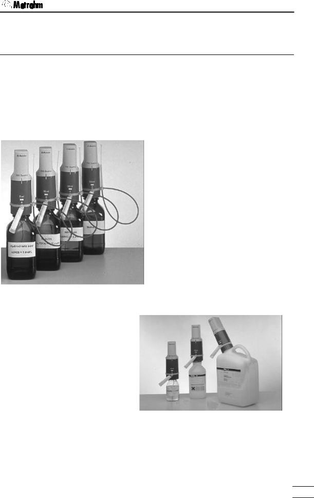
The Metrohm 700 Dosino is a versatile dosing drive which can be used for a wide range of demanding dosing tasks. It can be operated with various control instruments; this predestines it for use in complex automated systems.
The 700 Dosino can be placed directly on the reagent bottle. A range of threaded adapters ensures optimal fitting on the various types of bottle and threads. The size of the container is no longer important.
This type of assembly not only means that a lot of space is saved but, because the reagent is located below the drive, no escaping liquid can damage the drive.
Thanks to different 710 Dosing units (buret units) with 2, 5, 10, 20 or 50 mL dosing cylinders the Metrohm 700 Dosino is suitable for flexible use as a buret and can be adapted to a wide range of different applications.
Instead of the standard glass cylinder, dosing cylinders made of plastic (ETFE) are also available for use with aggressive alkalis.
Reagent exchange with the least possible loss of reagent is ensured as the design of the dosing unit has been optimized to provide the smallest possible dead volume.
700 Dosino, Instructions for use |
1 |
|
1. Overview
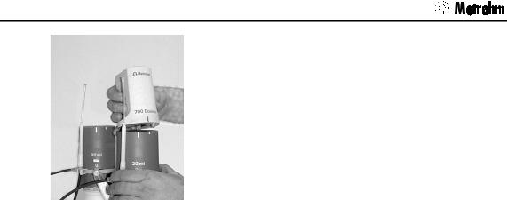
If reagents are exchanged frequently then the dosing unit can remain attached to the reagent bottle while the dosing drive is simply removed and attached to the next dosing unit.
1.2 Application possibilities
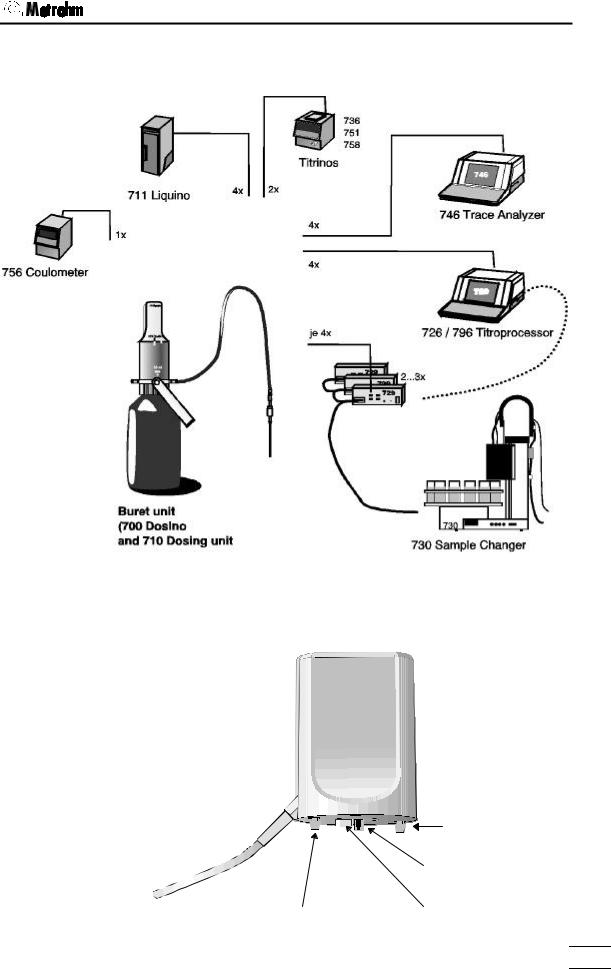
700 Dosino dosing drives are supported by various Metrohm instruments and are suitable for a wide range of different applications.
Titration
The following Metrohm titrators can control 700 Dosinos as titration burets:
∙726/796 Titroprocessor (connection for four Dosinos as standard; can be extended for up to twelve Dosinos * )
∙736 GP–Titrino (connection for two Dosinos)
∙751 GPD–Titrino (connection for two Dosinos)
∙758 KFD–Titrino (connection for two Dosinos)
Dosing
For complex dosing tasks, such as dosing controlled by time, dosing rate or temperature, the preparation of standard solutions and dilutions as well as pipetting or sample preparation the Dosino can be used with the
∙ 711 Liquino
As auxiliary buret the 700 Dosino can be used with e.g. the following Metrohm instruments:
∙ |
730 |
Sample changer (connection for up to twelve Dosinos * ) |
∙ |
756 |
KF–Coulometer (connection for one Dosino) |
∙ |
746 |
Trace analyzer (connection for four Dosinos) |
∙ |
726 |
Titroprocessor (connection for four Dosinos as standard; |
can be extended for up to twelve Dosinos * ) ∙ 736 GP–Titrino (connection for two Dosinos)
∙ 751 GPD–Titrino (connection for two Dosinos) ∙ 758 KFD–Titrino (connection for two Dosinos)
* Four Dosinos can be connected to the external bus of the control instrument via a 729 Dosimat Interface. Up to three 729 Dosimat Interfaces can be operated in cascade form on a single external bus.
2 |
700 Dosino, Instructions for Use |
|
1.3 Construction of the Dosino burets
1.2.1 The Dosino as a system component
1.3 Construction of the Dosino burets
1.3.1 The 700 Dosino dosing drive
|
guide cam |
|
push rod |
guide cam |
carrier |
700 Dosino, Instructions for use |
3 |
|

1. Overview
1.3.2 The 710 Dosing unit
710 Dosing unit |
710 Dosing unit |
with glass cylinder |
with ETFE cylinder |
Housing |
(PBTP) |
Spring clip |
(PBTP) |
Centering tube |
(PVDF) |
Dosing piston |
with piston peg |
(PTFE and graphite), |
6.1572.XXX |
(for glass cylinder) |
Glass cylinder (borosilicate glass) 6.1571.XX
ETFE dosing cylinder, complete with piston and stopcock washer 6.1566.XXX
Cylinder base (PTFE/graphite) 6.1573.XXX
Stopcock washer (silicon carbide ceramics)
Distributor with |
distributor disk |
(PVDF/ETFE) |
4 |
700 Dosino, Instructions for Use |
|
2.1 700 Dosino dosing drive
2 Setup
2.1 700 Dosino dosing drive
Checks
Please check immediately on receipt whether the shipment is complete and undamaged (compare with delivery note and list of accessories in section 4.4). If transport damage has occurred please refer to section 4.3 'Warranty'.
Location
The 700 Dosino is a robust instrument and can therefore be used under rough conditions in laboratories and factories.
However, care must be taken that it is not exposed to a corrosive atmosphere. Regular care of the instrument is essential if it is used under rough conditions.
If an instrument which has been stored under cold conditions is brought into a warm room then it is possible that the atmospheric humidity could cause water to condense inside the instrument. In order to avoid damage to the instrument it should be allowed to acclimatize itself for at least one hour before it is switched on.
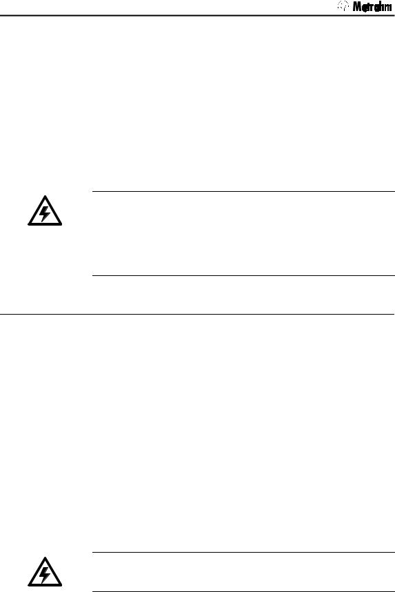
2.1.1 Connecting to a control instrument
The 700 Dosino is supplied with one of two different plugs. Please check that your model is fitted with the correct plug.
∙Model 2.700.0010 with 9-pin plug (DB9) for connection to the following instruments:
−726 Titroprocessor
−729 Dosimat Interface (for connection to 730 Sample Changer or 726 Titroprocessor)
−693 VA Processor
−746 Trace Analyzer
−695 Autosampler
The 6.2134.010 Adapter cable can be used for connecting Model 2.700.0020 (mini-DIN plug) to the instruments listed above.
700 Dosino, Instructions for Use |
5 |
|
2. Setup
∙Model 2.700.0020 with mini-DIN plug
for connection to the following instruments:
−711 Liquino
−736, 751, 758, 784, 785 Titrinos
−756 KF–Coulometer
The 6.2134.020 Adapter cable can be used for connecting Model 2.700.0010 (DB9-plug) to the instruments listed above.
The location of the correct connection socket for the Dosino can be found in the ‘Instructions for Use’ of the corresponding control unit.
Only connect the Dosino to a control instrument when this is switched off. The control instrument only recognizes the Dosino during the switching-on process.
Please note the arrangement of the connection sockets. Do not try to plug in the connection cable by using force!
2.1.2 Safety information
General:
This instrument left our factory in perfect condition from a safety point of view (see technical data, safety specification). The following information must be carefully observed in order to maintain this condition and to ensure hazard-free operation.
Connection to a control instrument:
This instrument must only be connected to that connection socket of a Metrohm instrument which is provided for it (see corresponding ‘Instructions for Use’). Only those adapter cables listed in the instructions are to be used.
Repairs and maintenance:
If faults or malfunctions occur during the operation of the 700 Dosino it is recommended that the connections with the control instrument are first checked to see if they are correct.
The Dosino (dosing drive) must not be opened. This should only be carried out by authorized service personnel.
6 |
700 Dosino, Instructions for Use |
|
2.2 710 Dosing unit
2.2 710 Dosing unit
Checks
Please check immediately on receipt whether the shipment is complete and undamaged (compare with delivery note and list of accessories in section 4.5). If transport damage has occurred please refer to section 4.4 'Warranty'.
2.2.1 Mounting the dosing units
Dosing units are available with different cylinder volumes from 2 to 50 mL (see accessory list, p. 45). Dosing units with glass cylinders (ordering no. 6.3031.XXX) are available for standard applications such as dosing and titrating with non-aggressive solutions. For dosing aggressive media such as strong alkalis we recommend the use of dosing units with ETFE cylinders (ordering no. 6.3030.XXX). Dosing units must be ordered separately.
Standard situation
Dosing units can be mounted directly on reagent bottles with a GL45 thread. Suitable threaded adapters are available for bottles from different chemical manufacturers (see accessories list, p. 45).
∙First attach the 6.2052.000 Buret tip holder to the white plastic ring of the dosing unit. Insert the double web of the holder into the upper edge of the ring until it reaches the notch and then, using a little pressure, carefully tilt the buret tip holder downwards until the individual webs snap into the lower edge of the ring. A buret tip can now be suspended from the holder with the tip facing upwards.
Buret tip holder
∙Screw the 6.1829.010 Aspiration tubing tightly onto the threaded connection on the lower surface of the dosing unit. This is the filling port (Dosino Port 2). Make care that the tubing is attached tightly so that no air bubbles can penetrate when the reagent solution is aspirated. Tighten the screw nipple firmly by hand.
700 Dosino, Instructions for Use |
7 |
|

2. Setup
If it is not possible to loosen a connection nipple by hand then you should use the 6.2739.000 Spanner supplied. Using the spanner to tighten up a nipple can damage the tubing connection.
∙Place the dosing unit on the reagent bottle and screw it down. Tighten the fixing ring (on the distributor) firmly. It is now possible to rotate the upper part of the housing in any direction you require.
If the thread does not fit then you must use a threaded adapter, see p. 45.
∙Fill the 6.1619.000 Adsorber tube with a suitable adsorption material for the reagent, e.g.
−Molecular sieve for moisture-sensitive solutions such as KF solutions or others.
−Soda lime for sodium hydroxide (CO2 adsorption)
∙Screw the adsorber tube onto connection port 0 of the dosing unit. Port 0 vents the reagent bottle. It should never be closed completely. If no adsorber tube is required then Port 0 must remain open.
∙Mount the 6.1805.100 Dosing tubing on Port 1 of the dosing unit. Tighten the connection nipple by hand.
∙Depending on the application you can now screw the 6.1543.050 Titrating tip with anti-diffusion valve or the 6.1543.060 Dosing tip onto the dosing tubing. The 6.1446.030 Ball stopper supplied can be used to fix the tip in an NS14/15 ground joint opening.
8 |
700 Dosino, Instructions for Use |
|
2.2 710 Dosing unit
2.2.2 Placing the drive on the 710 Dosing unit
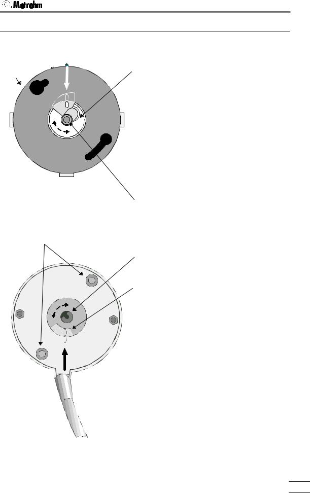
Check the positions of the centering tube and dosing piston of the dosing unit.
housing
guide cams
rib on rib |
centering tube with |
recess |
∙ The plastic rib in the recess of the centering tube must be flush with the plastic rib on the dosing unit housing (rib on rib).
∙ If necessary rotate the centering ring by hand until the rib on rib position is obtained.
∙ Check the piston peg. It has to be flush with the upper edge of the dosing unit. If this is not the case, see chapter 2.2.3, next page
piston peg
Check the position of the carrier disk of the drive.
push rod
carrier on carrier disk
|
∙ The plastic rib of the carrier disk must be |
|
flush with the plastic rib on the base plate |
rib on rib |
of the drive (rib on rib). |
∙ If necessary rotate the centering ring by hand until the ribon rib position is obtained.
Please note!
The dosing drive carrier can only be adjusted when the control instrument to which it is connected is switched off.
700 Dosino, Instructions for Use |
9 |
|
2. Setup
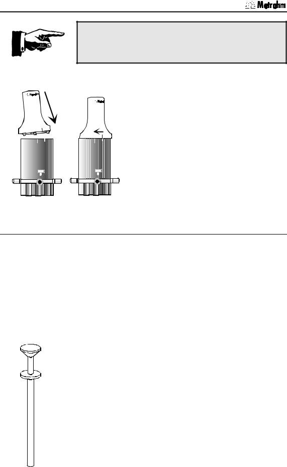
Never use force when attaching the dosing drive!
∙Place the dosing drive (700 Dosino) on the 710 Dosing unit.
700 Dosino
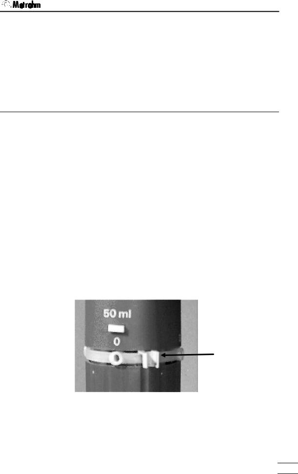
The green line on the Dosino must coincide with the short white marking of the dosing unit; see accompanying diagram.
The guide cams of the Dosino must be located in the openings provided for them.
10 ml |
10 ml |
∙Lock the drive, i.e. turn to the left (counterclockwise) until the stop is reached.
The green line on the Dosino must now coincide with the long white marking of the dosing unit; see accompanying diagram.
2.2.3 Problems in attaching the dosing drive?
If the dosing unit cannot be attached then either the stopcock washer of the Dosino or the centering tube of the dosing unit may not be in the exchange position.
The stopcock washer carrier must fit in the dosing unit recess provided for it. Please consult the previous diagrams.
The peg of the piston must be flush with the upper edge of the dosing unit.
How to adjust the dosing piston:
Each Dosino is supplied with piston pliers (6.1546.030); see accompanying diagram.
∙ Press the white knob of the piston pliers. Two wire loops appear at the piston pliers tip.
∙Position the piston pliers so that these wire loops surround the piston peg.
∙If you now release the knob carefully the piston pliers will snap shut and you can pull out the piston with the white knob (some force is required).
Take care with the 2 mL cylinder! In contrast to the larger dosing cylinders it is possible to pull out the piston completely. You should only pull out this piston so far (and carefully) that
10 |
700 Dosino, Instructions for Use |
|
2.2 710 Dosing unit
the gray upper edge of the dosing piston is just visible.
∙Release the piston pliers by pressing the white knob.
∙Then press the inverted dosing unit against a flat surface. The piston should now be flush with the upper edge of the dosing unit.
2.2.4Removing the dosing drive from the 710 Dosing unit
10 ml
A dosing drive can only be removed from a dosing unit when the four-way valve is in Position 2 (filling port, exchange position).
∙Press the <EXCH>, <FILL> or [Fill] key on the control instrument. The valve will automatically turn to the 'Exchange' position.
Detailed information about the manual operation of Dosinos can be found in the ‘Instructions for Use’ of your instrument.
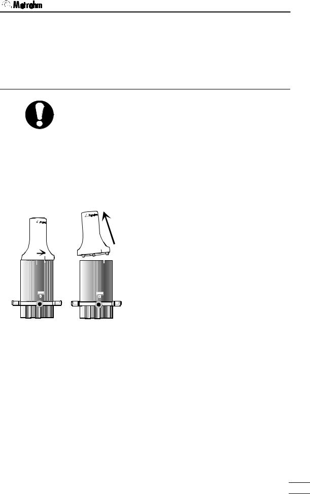
700 Dosino
10 ml
∙The drive mounted on the dosing unit is unlocked by rotating the Dosino to the right (clockwise).
The green line on the Dosino must now coincide with the shorter white marking of the dosing unit.
∙The dosing drive can now be lifted off upwards.
∙Never adjust the carrier of the Dosino or the centering tube of the dosing unit when these have been separated from each other. This could make attaching the dosing unit more difficult; please refer to the explanations on the previous page.
700 Dosino, Instructions for Use |
11 |
|
Loading...