


 Loading...
CD RECEIVER
KDC-138/138CR KDC-139/139S
SERVICE MANUAL
© 2007-9 PRINTED IN JAPAN B53-0577-00 (N) 373
Panel assy |
Panel assy |
KDC-138 (A64-4276-02) |
KDC-138CR (A64-4277-02) |
KDC-138 |
KDC-138CR |
Panel assy |
|
|
|
KDC-139 (A64-4286-02) |
|
|
|
KDC-139S (A64-4287-02) |
TDF SPARE-PANEL |
|
|
|
|
|
|
|
MAIN UNIT NAME |
TDF PARTS No. |
TDF NAME |
KDC-139 |
KDC-138 |
Y33-2830-63 |
TDF-81D |
|
KDC-138CR |
Y33-2830-64 |
TDF-81DCR |
|
KDC-139 |
Y33-2820-65 |
TDF-139 |
|
KDC-139S |
Y33-2820-66 |
TDF-139S |
Mounting hardware assy |
* Plastic cabinet assy |
* Carrying case |
|
(J21-9716-03) |
(A02-2736-03) |
(W01-1692-05) |
|
DC cord |
* Escutcheon |
Lever |
Screw set |
Screw (4x16) |
(E30-6415-15) |
(B07-xxxx-xx) |
(D10-4589-04) x2 |
(N99-1757-05) |
(N84-4016-48) |
* Depends on the model. Refer to the parts list.
This product uses Lead Free solder.
This product complies with the RoHS directive for the European market.

KDC-138/138CR/139/139S
BLOCK DIAGRAM
ELECTRIC UNIT (X34- )
J2 |
ANT. |
|
|
|
|
Q901-903 |
|
|
A1 |
|
DME1 |
|
|
|
|
||
AM+B |
BU |
|
|
DC-DET |
|
|
||
TUNER |
CD |
|
BU |
|
R103 |
|
||
A8V |
A8V |
|
|
BU5 |
||||
FRONT-END |
MECHA |
|
IC6 |
PHONE |
PHONE |
|||
SW5 |
SERVO+B |
|
||||||
|
|
|
|
|
||||
|
|
|
16 |
2 |
POWER |
|
Q101 |
|
3 |
|
|
IC |
|
|
|||
|
|
|
|
|
|
|
|
|
|
|
|
|
|
|
|
|
|
|
1 |
|
|
ACC DET |
ACC-DET |
|
|
|
|
|
|
|
|
|
|
|
|
|
|
|
|
|
|
|
|
|
|
|
|
|
|
|
|
|
|
|
|
|
|
|
Q103 |
BU5 |
|
|
|
|
|
|
|
|
|
|
|
|
|
|
|
BU DET |
BU-DET |
|
|
|
|
|
IC2 or IC3 |
|
|
|
|
|
|
|
|
J1 |
||||
|
|
|
|
|
|
|
|
|
|
|
|
|
|
||||
|
|
|
|
|
|
|
|
|
|
|
|
|
Q102 |
|
|||
|
|
|
|
|
|
|
|
|
1 |
|
|
Q701,702 |
J5 |
|
|
DC-CN |
|
|
|
|
|
|
|
|
|
|
|
|
|
|
|
||||
|
|
|
|
|
|
|
E-VOL |
|
MUTE |
|
|
|
|
SURGE- |
PHONE |
||
|
|
|
A8V |
|
|
|
|
|
|
PRE-OUT |
PRE-OUT |
|
DET |
||||
|
|
|
|
|
|
|
|
|
|
|
|
||||||
|
|
|
ROM CORRECTION (NOT USED) |
|
|
|
|
MUTE |
REAR/SW |
|
|
SP-OUT |
|||||
|
|
|
|
|
|
|
|
|
|
|
|
||||||
|
|
|
|
|
|
|
|
|
|
|
IC4 |
|
|||||
|
|
|
|
|
IC10 |
|
|
|
|
|
|
|
|
|
|
ACC |
|
|
|
|
|
|
|
|
|
|
|
|
BU5 |
|
|
|
|
||
|
|
|
SW5 |
E2PROM |
|
|
|
|
|
PS1 1 / PS1 2 / PS1 3 |
|
B.U. |
|||||
3 |
|
|
2 |
1 |
1 |
|
|
BU5 |
|
||||||||
|
|
|
|
|
|
|
|
|
P-ANT |
||||||||
IC1 |
|
|
|
|
|
|
|
|
|
|
|
Q705 |
PS2 1 / PS2 2 |
|
|||
|
|
|
|
|
|
|
|
|
|
|
|
|
|
|
P-CON |
||
|
|
|
|
|
|
|
|
|
|
|
|
|
|
|
|
|
|
|
|
|
|
|
|
|
|
|
|
|
BU5 |
BU DET |
|
FL+B |
|
|
|
|
|
|
|
|
|
|
|
|
|
|
|
MUTE |
RST |
|
AM+B |
|
|
|
|
|
|
|
|
|
|
|
|
|
|
|
|
|
|
||
|
|
|
|
|
SYSTEM u-COM |
|
|
|
9 |
|
|
|
SW5 |
POWER |
|
||
|
|
|
|
|
|
|
|
1 |
|
|
SUPPLY |
|
|||||
|
|
|
|
|
|
|
|
|
|
|
|
|
|
|
|
||
|
|
|
|
|
|
|
|
|
|
|
|
|
|
|
A8V |
IC |
|
|
|
|
|
|
|
|
|
|
|
|
|
|
|
|
|
|
|
|
|
|
|
|
|
|
|
|
|
|
|
DC-CN etc |
|
|
SW5 |
|
|
|
IC8 |
|
1 |
1 |
2 |
1 |
1 |
5 |
|
|
|
|
|
D5 |
|
|
|
|
|
|
|
|
PHONE |
|
|
|
|
||||||||
|
|
|
|
|
|
|
BU5 |
|
|
||||||||
BU5 |
RESET IC |
|
|
|
|
Q301 |
|
|
|
ACC DET / BU DET |
|
|
|
||||
|
|
|
|
|
|
|
P.ON FL |
|
|
|
|
|
|||||
|
|
|
|
|
|
SW5 |
BU5 |
|
ILLUMI+B |
|
|
PS1-1 / PS1-2 / PS1-3 |
|
SERVO+B |
CD |
|
|
|
|
|
|
|
|
|
|
|
PS2-1 / PS2-2 |
|
|
|
|||||
|
|
|
|
|
|
|
PAN5V |
|
|
|
|
|
|
|
Q2 |
|
|
|
|
|
|
|
|
|
|
|
|
|
|
|
|
|
|
|
|
|
|
|
|
|
|
|
|
|
|
|
|
|
|
|
|
SERVO |
|
|
|
|
J3 |
|
|
|
|
|
|
|
|
|
|
|
|
|
|
|
|
|
CN |
|
|
|
|
|
|
|
|
|
|
|
|
|
|
to GND |
|
J1 |
|
|
|
|
|
|
|
|
|
|
|
|
|
|
|
|
|
|
|
|
|
|
|
|
|
|
|
|
|
|
|
||
PANEL DET |
|
|
|
|
|
|
|
|
|
|
|
|
|
|
|
||
|
|
|
|
|
|
|
|
IC1 |
|
|
ED1 |
|
|
|
|
|
|
S2 |
|
J2 |
S1 |
|
|
|
|
|
|
|
|
|
|
|
|
|
|
RESET |
F-AUX |
ROTARY |
|
|
LCD |
|
|
|
LED |
|
|
|
|
|
|||
ENCODER |
|
|
DRIVER |
|
|
|
|
|
|
|
|
||||||
|
|
|
|
|
|
|
|
|
|
|
|
|
|
||||
|
|
|
|
SW5 |
|
|
|
|
KEY |
|
|
|
|
|
|
|
|
|
|
|
|
|
|
|
|
ILLUMI |
|
|
|
|
|
|
|
||
|
|
|
|
|
|
|
|
|
|
|
|
|
|
|
|
||
|
|
IC2 |
SW5 |
|
|
|
10 |
KEY |
|
|
|
|
|
|
|
|
|
|
|
|
|
|
|
|
|
|
|
|
|
|
|
||||
|
|
REMOTE |
|
|
|
|
|
MATRIX |
|
|
|
|
|
|
|
||
|
|
|
|
|
|
|
|
|
|
|
|
|
|
|
|
||
SWITCH UNIT (X16- ) |
|
|
|
|
|
|
|
|
|
|
|
|
|
|
|||
|
|
|
|
|
|
CD PLAYER UNIT (X32-598x-xx) |
|
|
|
|
|
MOTHER |
|
||||
|
|
|
|
|
|
|
|
|
|
|
|
|
|
|
|
||
|
|
DPU1 |
|
|
|
|
|
IC1 |
|
|
|
|
|
BOARD (X34- ) |
|
||
|
|
|
|
|
|
|
|
|
|
|
|
|
|
|
|
||
|
|
|
|
|
|
|
|
|
|
RST |
|
|
|
|
|
MRST |
|
|
|
|
|
|
|
|
D.GND |
A,B,C,E,F |
|
MSTOP |
|
|
|
|
|
MSTOP |
|
|
|
|
A |
B |
|
|
|
|
|
|
Q3 |
|
|
|
|
|
|
|
|
|
F |
|
|
|
|
CLK |
|
LEVEL SHIFT |
CLK |
|
|||||
|
|
|
E |
|
|
|
|
|
LEVEL SHIFT Q3 |
|
|||||||
|
|
|
|
|
|
|
|
|
|
|
|
|
|
||||
|
|
|
C |
|
|
Q7 |
|
1 CHIP IC |
DATA |
|
|
|
DATA |
|
|||
|
|
|
|
|
|
|
APC |
|
RF AMP |
|
|
Q4 |
LEVEL SHIFT |
|
|
||
|
|
|
|
|
|
|
|
|
+ |
|
|
MUTE |
|
||||
|
|
|
|
|
|
|
|
|
SERVO |
|
|
|
|
|
|
MUTE |
|
|
|
|
|
|
|
|
|
|
PROCESSOR |
|
|
(0-00),(0-01) ONLY |
|
||||
|
|
|
|
|
|
|
|
|
|
|
|
|
|||||
|
|
|
|
|
|
|
|
|
+ |
|
|
|
|
||||
|
|
|
|
|
|
IC6 |
|
|
|
|
|
|
|
L-ch |
|
||
|
|
|
|
|
|
|
MICRO |
|
|
|
|
|
|
|
|||
|
|
|
|
|
|
|
|
|
|
|
|
|
|
|
R-ch |
|
|
|
|
|
FO COIL |
|
|
FO OUT |
|
PROCESSOR |
|
|
|
|
|
|
A.GND |
|
|
|
|
|
|
|
|
|
|
|
|
|
|
|
|
|
|
|
|
|
|
|
TR COIL |
|
|
TR OUT |
|
|
AVDD |
IC3 |
3.3V REG |
8V SW |
Q1 |
|
AS8V |
|
|
|
|
|
|
|
|
|
VREF |
|
VREF |
|
|
||||||
|
|
|
|
|
|
|
|
|
|
|
|
|
|
|
|
||
|
|
|
|
|
|
|
MOTOR |
FOD,TRD, |
|
|
|
Q8,9 SW |
Q2 |
(0-00),(0-01) |
|
|
|
|
|
|
DM1 |
|
|
|
TVD,SPL |
|
|
|
SW |
ONLY |
|
|
|||
|
|
|
|
|
|
DRIVER |
|
|
|
|
|
|
|
|
|
|
|
|
|
|
SPINDLE |
|
|
DM OUT |
|
DMUTE |
|
|
|
|
|
|
D.GND |
|
|
|
|
|
MOTOR |
|
|
|
|
|
|
|
|
D.GND |
|
|
|||
|
|
|
|
|
|
|
|
|
Q6 |
IC2 |
|
|
|
||||
|
|
|
|
|
|
|
|
|
|
|
|
|
|
|
|
||
|
|
|
DM2 |
|
|
|
|
|
|
IOVDD |
|
3.3V SW |
3.3V REG |
BU5V |
|
||
|
|
|
LOADING & |
|
|
|
|
|
|
|
|
|
|
|
|
|
|
|
|
|
SLED |
|
|
|
FM OUT |
|
|
|
|
|
|
|
|
S7V |
|
|
|
|
MOTOR |
|
|
|
|
|
P-ON1 |
|
SW |
|
|
|
|
||
|
|
|
|
|
|
|
|
|
(0-01),(0-03) |
|
|
||||||
|
|
|
|
|
|
|
|
|
|
|
|
|
|||||
|
|
|
|
|
|
|
|
|
REGVDD |
|
|
ONLY |
|
|
|
||
|
|
|
|
|
|
|
|
|
|
|
|
|
|
|
|
||
|
|
|
|
|
|
|
S.GND |
|
|
|
|
|
|
S4 |
8EJE-SW |
|
|
|
|
|
|
|
|
|
|
|
X1 or |
|
|
|
|
|
|
|
|
|
|
|
|
|
|
|
|
|
D.GND |
|
|
|
|
|
|
|
|
|
|
|
|
|
|
|
|
|
X2 |
|
|
|
|
S3 |
|
|
|
|
|
|
|
|
|
|
|
|
|
|
|
|
|
|
|
||
|
|
|
|
|
|
|
|
|
CLOCK |
|
|
|
|
|
LOE/LIM-SW |
|
|
|
|
|
|
|
|
|
|
|
|
|
|
|
|
|
|
||
|
|
|
|
|
|
|
|
|
16.93MHz |
|
|
|
|
|
S2 |
|
|
|
|
|
|
|
|
|
|
|
|
|
|
|
|
|
12EJE-SW |
|
|
|
|
|
|
|
|
|
|
|
|
|
|
|
|
|
|
|
|
|
|
|
|
|
|
|
|
|
|
|
|
|
|
|
S1 |
LOS-SW |
|
|
|
|
|
|
|
|
|
|
|
|
|
|
|
|
|
|
|
|
|
|
|
|
|
|
|
|
|
|
|
|
D.GND |
S.GND |
S.GND |
|
|
|
|
|
|
|
|
|
|
|
|
|
|
|
LO/EJ |
|
|||
|
|
|
|
|
|
|
|
|
|
|
|
|
|
|
|
|
|
|
|
|
|
|
|
|
|
|
|
|
|
|
|
|
|
MOTOR |
|
2
KDC-138/138CR/139/139S
COMPONENTS DESCRIPTION
● ELECTRIC UNIT (X34-564x-xx)
Ref. No. |
Application / Function |
Operation / Condition / Compatibility |
|
|
|
IC1 |
System µ-COM |
Controls FM/AM tuner, the changer, CD mechanism, panel, volume and tone. |
|
|
|
IC2,3 |
E-VOL |
Controls the source, volume and tone. |
|
|
|
IC4 |
Power Supply IC |
Outputs 5Vx2, 8.1Vx2, 10.2V, P-CON and P-ANT. |
|
|
|
IC6 |
Power IC |
Amplifies the front L/R and the rear L/R to 50W or 45W maximum. |
|
|
|
IC8 |
Reset IC |
Lo when detection voltage goes below 3.6V. |
|
|
|
Q2 |
Servo+B AVR |
When Q3’s base goes Hi, Servo+B AVR outputs 7.5V. |
|
|
|
Q3 |
Control SW for Servo+B |
ON when the base goes Hi. |
|
|
|
Q11 |
14V SW |
ON when the base goes Hi. |
|
|
|
Q12 |
14V SW |
ON when the base goes Lo. |
|
|
|
Q13 |
Control SW for IC4 |
ON when the base goes Hi. |
|
|
|
Q14 |
Control SW for IC4 |
ON when the base goes Lo. |
|
|
|
Q101 |
ACC DET |
ON when the base goes Hi during ACC is applied. |
|
|
|
Q102 |
Serge DET |
When the base goes Hi, surge voltage is detected. |
|
|
|
Q103 |
BU DET |
ON when the base goes Hi during BU is applied. |
|
|
|
Q104,105 |
Mute Control |
ON when the base goes Hi. |
|
|
|
Q301 |
Panel 5V SW |
ON when the base goes Lo. |
|
|
|
Q402 |
Quick Charge Voltage SW |
Charges voltage quickly when the base goes Hi. |
|
|
|
Q701,702 |
Pre-out Mute SW |
When a base of the 4 transistors goes Hi, pre-out is muted. |
|
|
|
Q705 |
Mute Driver for Pre-out |
ON when the base goes Lo. |
|
|
|
Q801 |
Electric Discharge Circuit for C805 (SVR) |
ON when the base goes Lo. |
|
|
|
Q901 |
DC Offset DET |
ON when the base goes Hi after Q902’s and Q903’s outputs are separated. |
|
|
|
Q902,903 |
DC Offset DET SW |
ON when the bases go Lo after IC6’s SP-OUTs (DC) are separated. |
|
|
|
● SWITCH UNIT (X16-616x-xx)
Ref. No. |
Application / Function |
Operation / Condition / Compatibility |
|
|
|
IC1 |
LCD Driver |
|
|
|
|
IC2 |
Remote Control Sensor |
|
|
|
|
● CD PLAYER UNIT (X32-5980-04)
Ref. No. |
Application / Function |
Operation / Condition / Compatibility |
|
|
|
|
|
|
|
Focusing, tracking, sled and spindle servo processing. |
|
|
|
Automatic adjustment (focusing, tracking, gain, offset and balance) operations. |
|
|
CD Signal Processor |
Digital signal processing (DSP, PLL, sub-codes, CIRC error correction, audio data |
|
IC1 |
& MECHA µ-COM |
interpolation processing) operations, and microcomputer function. |
|
RF Amplifier responding |
Generation of RF signal based on the signals from the APC circuit and the laser pick-up, |
||
|
|||
|
to CD-RW |
and generation of servo error (focusing error and tracking error) signals. |
|
|
|
Detection of dropout, anti-shock, track crossing and off-tracking conditions, included gain |
|
|
|
control function during CD-RW. |
|
|
|
|
|
IC2 |
3.3V REG |
Supplies 3.3V to IC1 and the laser pick-up. |
|
|
|
|
|
IC6 |
4ch BTL Driver |
Focusing and tracking coil, sled and spindle motor driver, disc loading and eject operation. |
|
|
|
|
3
KDC-138/138CR/139/139S
COMPONENTS DESCRIPTION
Ref. No. |
Application / Function |
Operation / Condition / Compatibility |
|
|
|
Q3 |
5V-3.3V Level Shift |
Shifts 5V to 3.3V, or 3.3V to 5V. |
|
|
|
Q4 |
5V-3.3V Level Shift |
Shifts 3.3V to 5V. |
|
|
|
Q6 |
BU3.3V SW |
Q6 is ON when Q8 or Q9 is ON. |
|
|
|
Q7 |
APC (Auto Power Control) |
Drives LD (Laser Diode). |
|
|
|
Q8 |
Power Supply Control |
Power Supply Control from MECHA µ-COM. Q6 is ON when pin 63 (P_ON1) of IC1 is Hi. |
|
|
|
Q9 |
Power Supply Control |
Power Supply Control from system µ-COM. Q6 is ON when pin 125 (MSTOP) of IC1 is Hi. |
|
|
|
D1,2 |
5V Force Voltage Prevention |
5V Force Voltage Prevention from MECHA µ-COM side. |
|
|
|
D3 |
Laser Diode Protection |
Prevents reverse bias which is applied to laser. Laser destruction prevention. |
|
|
|
D4 |
Static Electricity Countermeasure |
Prevents malfunction by static electricity. |
|
|
|
4
KDC-138/138CR/139/139S
MICROCOMPUTER’S TERMINAL DESCRIPTION
● SYSTEM µ-COM: IC1 on X34- (ELECTRIC UNIT)
Pin No. |
|
Pin Name |
I/O |
Application |
Truth Value |
Processing Operation Description |
|||
|
Table |
||||||||
|
|
|
|
|
|
|
|
|
|
|
|
|
|
|
|
|
|
|
|
1 |
LX DATA M |
I/O |
Data to slave unit |
|
Pull-down (GND) |
||||
|
|
|
|
|
|
|
|
|
|
2 |
LX CLK |
I/O |
LX-BUS clock |
|
125k~65kHz |
||||
|
|
|
|
|
|
|
|
|
|
3~5 |
NC |
- |
Not used |
|
Output L fixed |
||||
|
|
|
|
|
|
|
|
|
|
6 |
REMO |
I |
Remote control signal input |
|
Detects pulse width |
||||
|
|
|
|
|
|
|
|
|
|
7 |
NC |
- |
Not used |
|
Output L fixed |
||||
|
|
|
|
|
|
|
|
|
|
8 |
BYTE |
- |
Memory extended bus width setting |
|
Connects to VSS |
||||
|
|
|
|
|
|
|
|
|
|
9 |
CNVSS |
- |
|
|
Connects to VSS |
||||
|
|
|
|
|
|
|
|
|
|
10 |
XCIN |
- |
32.768kHz |
|
|
||||
|
|
|
|
|
|
|
|
|
|
11 |
XCOUT |
- |
32.768kHz |
|
|
||||
|
|
|
|
|
|
|
|
|
|
|
|
|
|
|
|
- |
|
|
L: Reset |
12 |
RESET |
|
|
||||||
|
|
|
|
|
|
|
|
|
|
13 |
XOUT |
- |
10.0MHz |
|
|
||||
|
|
|
|
|
|
|
|
|
|
14 |
VSS |
- |
|
|
|
||||
|
|
|
|
|
|
|
|
|
|
15 |
XIN |
- |
10.0MHz |
|
|
||||
|
|
|
|
|
|
|
|
|
|
16 |
VCC1 |
- |
|
|
|
||||
|
|
|
|
|
|
|
|
|
|
17 |
NMI |
I |
|
|
Connects to VCC |
||||
|
|
|
|
|
|
|
|
|
|
|
|
|
|
|
I |
Panel communication detection |
|
H: Panel detached, L: Panel attached |
|
18 |
PANEL DET |
|
|||||||
|
|
|
|
|
|
|
|
|
|
19,20 |
NC |
- |
Not used |
|
Output L fixed |
||||
|
|
|
|
|
|
|
|
|
|
21 |
ROMCOR DET |
I |
E2PROM writing request |
|
H: Writing |
||||
|
|
|
|
|
|
|
|
|
|
22,23 |
NC |
- |
Not used |
|
Output L fixed |
||||
|
|
|
|
|
|
|
|
|
|
24 |
PON FL |
- |
Not used |
|
Output L fixed |
||||
|
|
|
|
|
|
|
|
|
|
25 |
NC |
- |
Not used |
|
Output L fixed |
||||
|
|
|
|
|
|
|
|
|
|
|
|
|
|
|
|
|
|
|
ON: L, Momentary power down/Panel detached: |
26 |
PON PANEL |
I/O |
Panel 5V control |
|
|||||
|
Hi-Z, 11 minutes after ACC OFF: Hi-Z |
||||||||
|
|
|
|
|
|
|
|
|
|
|
|
|
|
|
|
|
|
|
|
27,28 |
NC |
- |
Not used |
|
Output L fixed |
||||
|
|
|
|
|
|
|
|
|
|
29 |
AUD SCL |
I/O |
E-VOL clock output |
|
|
||||
|
|
|
|
|
|
|
|
|
|
30 |
AUD SDA |
I/O |
E-VOL data input/output |
|
|
||||
|
|
|
|
|
|
|
|
|
|
31 |
VFD SYS DATA |
O |
LCD data output |
|
|
||||
|
|
|
|
|
|
|
|
|
|
32 |
VFD PAN DATA |
I |
LCD data input |
|
|
||||
|
|
|
|
|
|
|
|
|
|
33 |
VFD CLK |
O |
LCD clock output |
|
125kHz |
||||
|
|
|
|
|
|
|
|
|
|
34 |
VFD BLK |
- |
Not used |
|
Output L fixed |
||||
|
|
|
|
|
|
|
|
|
|
35 |
CD DATA |
I/O |
CD mechanism I2C data input/output |
|
|
||||
|
|
|
|
|
|
|
|
|
|
36 |
CD CLK |
I/O |
CD mechanism I2C clock output |
|
|
||||
|
|
|
|
|
|
|
|
|
|
37 |
NC |
- |
Not used |
|
Output L fixed |
||||
|
|
|
|
|
|
|
|
|
|
38 |
CD LOS SW |
I |
CD loading detection |
|
|
||||
|
|
|
|
|
|
|
|
|
|
39 |
PIO0 |
I |
Communication request from mechanism DSP |
|
H: Data request |
||||
|
|
|
|
|
|
|
|
|
|
40 |
CD MSTOP |
O |
CD mechanism µ-com stop |
|
H: Mechanism µ-com operates, |
||||
|
L: Mechanism µ-com stops |
||||||||
|
|
|
|
|
|
|
|
|
|
|
|
|
|
|
|
|
|
|
|
41 |
EPM |
I |
Flash EPM input |
|
Connects to VSS |
||||
|
|
|
|
|
|
|
|
|
|
42 |
CD LOE LIM SW |
I |
CD detection (Chucking SW) |
|
H: Loading completed, L: No disc |
||||
|
|
|
|
|
|
|
|
|
|
43 |
PON CD |
- |
Not used |
|
|
||||
|
|
|
|
|
|
|
|
|
|
5
KDC-138/138CR/139/139S
MICROCOMPUTER’S TERMINAL DESCRIPTION
Pin No. |
|
Pin Name |
I/O |
Application |
Truth Value |
Processing Operation Description |
||
|
Table |
|||||||
|
|
|
|
|
|
|
|
|
|
|
|
|
|
|
|
|
|
44 |
|
CD LOEJ |
I/O |
CD motor control |
q |
Refer to the truth value table |
||
|
|
|
|
|
|
|
|
|
45 |
|
CD MOTOR |
I/O |
CD motor control |
q |
Refer to the truth value table |
||
|
|
|
|
|
|
|
|
|
46 |
|
VFD CE |
O |
LCD control request |
|
|
||
|
|
|
|
|
|
|
|
|
47 |
|
CD DRIVEMUTE |
O |
Motor driver mute output |
|
|
||
|
|
|
|
|
|
|
|
|
48 |
|
CD CCE |
O |
CD mechanism chip enable |
|
|
||
|
|
|
|
|
|
|
|
|
49 |
|
NC |
I |
Not used |
|
|
||
|
|
|
|
|
|
|
|
|
50 |
|
CD MRST |
O |
CD mechanism µ-com reset |
|
H: Normal, L: Reset |
||
|
|
|
|
|
|
|
|
|
51~53 |
|
NC |
- |
Not used |
|
Output L fixed |
||
|
|
|
|
|
|
|
|
|
54 |
|
CD MUTE |
I |
CD mute request |
|
L: Mute request |
||
|
|
|
|
|
|
|
|
|
55 |
|
CD DISC12 SW |
I |
12cm disc detection |
|
Pull-up (B.U.) |
||
|
|
|
|
|
|
|
|
|
56 |
|
ROTARY CCW |
I |
VOL key input |
|
Detects pulse width |
||
|
|
|
|
|
|
|
|
|
57 |
|
ROTARY CW |
I |
VOL key input |
|
Detects pulse width |
||
|
|
|
|
|
|
|
|
|
58~61 |
|
NC |
- |
Not used |
|
Output L fixed |
||
|
|
|
|
|
|
|
|
|
62 |
|
VCC2 |
- |
|
|
|
||
|
|
|
|
|
|
|
|
|
63 |
|
NC |
- |
Not used |
|
Output L fixed |
||
|
|
|
|
|
|
|
|
|
64 |
|
VSS |
- |
|
|
|
||
|
|
|
|
|
|
|
|
|
65 |
|
NC |
- |
Not used |
|
|
||
|
|
|
|
|
|
|
|
|
66 |
|
TUN IFC OUT |
I |
Front-end IFC-OUT input |
|
H: Station found, L: No station |
||
|
|
|
|
|
|
|
|
|
67 |
|
PON EXT GND |
I/O |
IC2 external input quick charge control |
|
L: OFF, Hi-Z: Quick charge, When IC2 is in source select: |
||
|
|
Hi-Z, Mute L: L, Momentary power down/Power OFF: L |
||||||
|
|
|
|
|
|
|
|
|
|
|
|
|
|
|
|
|
|
68 |
|
MUTE |
I/O |
Mute |
|
L: Mute OFF, Hi-Z: Mute ON |
||
|
|
|
|
|
|
|
|
|
69 |
|
ANALOG CON |
O |
AUX/LX audio switching |
|
AUX: H (Switches after 100ms after first-out mute |
||
|
|
begins to work), LX/Other source: L |
||||||
|
|
|
|
|
|
|
|
|
|
|
|
|
|
|
|
|
|
70 |
|
LX RST |
O |
Forced reset to slave unit |
|
H: Reset, L: Normal |
||
|
|
|
|
|
|
|
|
|
71 |
|
LX CON |
O |
Start-up request to slave unit |
|
H: Slave unit ON, L: Slave unit OFF |
||
|
|
|
|
|
|
|
|
|
72 |
|
LX MUTE |
I |
Mute request from slave unit |
|
H: Mute ON, L: Mute OFF |
||
|
|
|
|
|
|
|
|
|
73 |
|
LX REQ M |
O |
Communication request to slave unit |
|
|
||
|
|
|
|
|
|
|
|
|
74 |
|
NC |
- |
Not used |
|
|
||
|
|
|
|
|
|
|
|
|
75 |
|
LX REQ S |
I |
Communication request from slave unit |
|
Pull-down (GND) |
||
|
|
|
|
|
|
|
|
|
76 |
|
PWIC SVR |
O |
SVR discharging circuit |
|
During 500ms after power OFF and momentary |
||
|
|
power down: H, Since then: L |
||||||
|
|
|
|
|
|
|
|
|
|
|
|
|
|
|
|
|
|
77 |
|
PWIC STBY |
O |
Power IC standby control |
|
Power ON: H, Power OFF: L |
||
|
|
|
|
|
|
|
|
|
78 |
|
PWIC MUTE |
O |
Power IC mute |
|
STANDBY source/Momentary power down: L, |
||
|
|
TEL mute: L |
||||||
|
|
|
|
|
|
|
|
|
|
|
|
|
|
|
|
|
|
|
|
|
|
|
I |
ACC power supply detection |
|
ACC found: L, No ACC: H |
79 |
|
ACC DET |
|
|||||
|
|
|
|
|
|
|
|
|
|
|
|
|
|
|
|
|
BU found: L, No BU/Momentary power down: H |
|
|
|
|
I |
Detection of momentary power down |
|
(Operates after less than 4ms after momentary |
|
80 |
|
BU DET |
|
|||||
|
|
|
|
|
|
|
|
power down is detected) |
|
|
|
|
|
|
|
|
|
81~83 |
|
NC |
- |
Not used |
|
Output L fixed |
||
|
|
|
|
|
|
|
|
|
84 |
|
TUN SMETER |
I |
S-meter input |
|
|
||
|
|
|
|
|
|
|
|
|
85 |
|
TYPE1 |
I |
Destination switching |
e |
Refer to the truth value table |
||
|
|
|
|
|
|
|
|
|
6
KDC-138/138CR/139/139S
MICROCOMPUTER’S TERMINAL DESCRIPTION
Pin No. |
Pin Name |
I/O |
Application |
Truth Value |
Processing Operation Description |
|
Table |
||||||
|
|
|
|
|
||
|
|
|
|
|
|
|
86 |
TYPE2 |
I |
Destination switching |
e |
Refer to the truth value table |
|
|
|
|
|
|
|
|
87 |
PWIC DC DET |
I |
DC offset detection |
|
If DC offset is found 20 times in 100ms with condition |
|
|
of over 1.0V, it will be judged as DC offset detected. |
|||||
|
|
|
|
|
||
|
|
|
|
|
|
|
88 |
LINE MUTE |
I |
Line mute detection |
|
TEL mute: Below 1V, NAVI mue: Over 2.5V |
|
|
|
|
|
|
|
|
89 |
OFFSET DET |
I |
Power IC offset detection |
|
|
|
|
|
|
|
|
|
|
90 |
PS2 2 |
O |
Power supply IC control |
r |
Refer to the truth value table |
|
|
|
|
|
|
|
|
91 |
PS2 1 |
O |
Power supply IC control |
r |
Refer to the truth value table |
|
|
|
|
|
|
|
|
92 |
PS1 1 |
O |
Power supply IC control |
r |
Refer to the truth value table |
|
|
|
|
|
|
|
|
93 |
PS1 2 |
O |
Power supply IC control |
r |
Refer to the truth value table |
|
|
|
|
|
|
|
|
94 |
PS1 3 |
O |
Power supply IC control |
r |
Refer to the truth value table |
|
|
|
|
|
|
|
|
95 |
NC |
- |
Not used |
|
Output L fixed |
|
|
|
|
|
|
|
|
96 |
AVSS |
- |
|
|
|
|
|
|
|
|
|
|
|
97 |
REF CON |
O |
VREF control |
|
Connects to VREF |
|
|
|
|
|
|
|
|
98 |
VREF |
- |
|
|
|
|
|
|
|
|
|
|
|
99 |
AVCC |
- |
|
|
|
|
|
|
|
|
|
|
|
100 |
LX DATA S |
I |
Data from slave unit |
|
Pull-down (GND) |
|
|
|
|
|
|
|
• Truth value table
q CD motor control
|
CD motor |
CD loading/eject |
|
|
|
|
|
Stop |
L |
L |
|
|
|
|
|
Load |
H |
L |
|
|
|
|
|
Eject |
H |
H |
|
|
|
|
|
Brake |
H |
Hi-z |
|
|
|
|
|
e Destination switching |
|
||
|
|
|
|
TYPE 2 |
TYPE 1 |
|
Model |
(Pin 86) |
(Pin 85) |
|
|
|
|
||
|
|
|
|
0V |
0V |
|
KDC-135 |
|
|
|
|
0V |
2.4V |
|
KDC-135CR |
|
|
|
|
1.2V |
0V |
|
KDC-136 |
|
|
|
|
r Power supply IC (IC4) control SEL1 (Pin 10)
PS1-2 |
PS1-3 |
PS2-1 |
ILLUMI |
P-CON |
P-ANT |
|
|
|
|
|
|
L |
L |
L |
OFF |
OFF |
OFF |
|
|
|
|
|
|
L |
L |
H |
ON |
OFF |
OFF |
|
|
|
|
|
|
H |
L |
H |
ON |
ON |
OFF |
|
|
|
|
|
|
H |
H |
H |
ON |
ON |
ON |
|
|
|
|
|
|
SEL2 (Pin 11) |
|
|
|
|
|
|
|
|
|
|
|
PS1-1 |
PS2-2 |
AUDIO/SW5 |
AM |
|
|
|
|
|
|
|
|
L |
L |
OFF |
OFF |
|
|
|
|
|
|
|
|
H |
L |
ON |
OFF |
|
|
|
|
|
|
|
|
H |
H |
ON |
ON |
|
|
|
|
|
|
|
|
7
KDC-138/138CR/139/139S
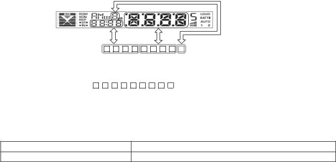
TEST MODE
■ Example
Key |
Description of display |
Description |
|
|
|
|
|
5 |
|
E J C X X X X X |
Disc EJECT times display. MAX 65535 (times) |
|
Disc EJECT times display |
|
|
■5 |
|
While disc EJECT times is displayed, press and hold for |
|
|
|
2 seconds or longer to clear disc EJECT times. |
|
|
|
|
|
|
|
|
|
A symbol “■” in the key column indicates that the key should be pressed and held for 1 second or longer. |
|||
■ How to enter the test mode
Procedure |
Note |
Press and hold the [1] key and [3] key and reset.
All lamps blink when it is detected that the sub-clock resonator is disconnected.
When having started up in the test mode, change the LINE MUTE inhibition time from 10 seconds to 1 second.
When operating in the test mode, even if a DC offset error occurs, detection information is not written in the E2PROM. Forced disc ejection is prohibited in the test mode.
■ How to clear the test mode
Procedure |
Note |
|
|
Reset, momentary power down, ACC OFF, Power OFF, Panel detached. |
Clearing the test mode |
|
|
■Test mode default condition
Description |
Default values |
|
|
Source |
STANDBY |
|
|
Display |
Display lights are all turned on. |
|
|
Volume |
-10dB (“30” is displayed.) |
|
|
Bass Boost |
OFF |
|
|
CRSC |
OFF regardless of having/not having the switching function. |
|
|
AUX |
ON (Only model equipped with AUX) |
|
|
System Q |
NATURAL (FLAT) |
|
|
Preout |
Rear |
|
|
8
|
|
|
|
|
|
|
|
|
|
|
|
|
|
|
KDC-138/138CR/139/139S |
||
|
|
|
|
|
|
|
|
|
|
|
|
TEST MODE |
|||||
■ Special displays when all lights are on in STANDBY source |
|||||||||||||||||
|
|
|
|
|
|
|
|
|
|
|
|
|
|
|
|||
Key |
Description of display |
|
|
|
|
|
Description |
|
|||||||||
|
|
|
|
|
|
|
|
|
|
|
|
|
|
|
|
|
|
Common |
All lights ON. |
|
|
|
|
|
|
|
|
|
All lights ON. |
|
|||||
|
|
|
|
|
|
|
|
|
|
|
|
|
|
|
|
|
|
|
|
|
|
|
|
Destination terminal |
|
|
|
|
T |
P |
1 |
1 |
|
“TYPE” indicates system µ-com (IC1) destination, and shows |
|
|
|
|
|
|
|
condition indication |
|
|
|
|
|
real-time condition of the destination terminal. |
|
||||
1 |
|
|
|
|
|
|
|
|
|
|
|
|
|||||
|
|
|
|
|
|
|
|
|
|
|
|
|
|
||||
Development ID |
|
5 |
: 0 |
0 |
7 |
0 |
1 |
K |
|
Development ID – Version (system µ-com: IC1) |
|
||||||
|
|
|
|
|
|
|
|
|
|||||||||
|
|
|
|
|
|
condition indication |
|
|
|
||||||||
|
|
|
|
|
|
|
|
|
|
|
|
|
|
|
|
|
|
|
|
|
|
|
|
|
|
|
|
|
|
|
|
|
|
|
|
2 |
|
|
Serial No. display |
0 |
0 |
0 |
0 |
0 |
0 |
0 |
0 |
|
Serial No. is displayed (8 digits) |
|
|||
|
|
|
|
|
|
|
|
|
|
|
|
|
|
|
|
|
|
|
|
|
|
|
|
|
P |
o |
n |
|
0 |
H |
X |
X |
|
00~50 is displayed for “XX”. When less than 1 hour, |
|
3 |
|
|
|
|
|
displayed by displayed by increments of 10 minutes. |
|
||||||||||
|
|
|
|
|
|
|
|
|
|
|
|
|
|||||
|
|
|
|
|
|
Power ON time display |
|
|
|
|
|
|
|
|
|
|
|
|
|
|
|
|
|
P |
o |
n |
X |
X |
X |
X |
X |
|
00001~10922 is displayed for “XXXXX”. MAX 10922 (hours) |
|
|
|
|
|
|
|
|
|
|
|
|
|
|
|
|
|
|
|
|
|
■3 |
|
|
|
|
|
|
|
|
|
|
When Power ON time is displayed, press and hold for |
|
||||
|
|
|
|
|
|
|
|
|
|
|
2 seconds or longer to clear Power ON time. |
|
|||||
|
|
|
|
|
|
|
|
|
|
|
|
|
|
|
|
|
|
|
|
|
|
|
|
|
|
|
|
|
|
|
|
|
|
|
|
|
|
|
|
|
|
|
P |
L |
y |
|
0 |
H |
X |
X |
|
00~50 is displayed for “XX”. When less than 1 hour, |
|
4 |
|
|
|
|
|
displayed by increments of 10 minutes. |
|
||||||||||
|
|
|
|
|
|
|
|
|
|
|
|
|
|||||
|
|
|
|
|
|
|
|
|
|
|
|
|
|
|
|
|
|
|
|
|
|
|
|
Disc operation time display |
P |
L |
y |
X |
X |
X |
X |
X |
|
00001~10922 is displayed for “XXXXX”. MAX 10922 (hours) |
|
|
|
|
|
|
|
|
|
|
|
|
|
|
|
|
|
|
|
|
|
|
|
|
|
|
|
|
|
|
|
|
|
|
While the disc operation time is displayed, press and hold for |
|
|
|
|
|
|
|
|
|
|
|
|
|
|
|
|
|
|
|
|
|
■4 |
|
|
|
|
|
|
|
|
|
|
2 seconds or longer to clear the disc operation time. |
|
||||
|
|
|
|
|
|
|
|
|
|
|
|
|
|
|
|
(Cleared only for displayed media.) |
|
|
|
|
|
|
|
|
|
|
|
|
|
|
|
|
|
|
|
5 |
|
|
|
E |
J |
C |
X |
X |
X |
X |
X |
|
Disc EJECT times display. MAX 65535 (times) |
|
|||
|
|
|
|
|
|
Disc EJECT times display |
|
|
|
|
|
|
|
|
|
|
|
|
■5 |
|
|
|
|
|
|
|
|
|
While disc EJECT times is displayed, press and hold for |
|
|||||
|
|
|
|
|
|
|
|
|
|
|
2 seconds or longer to clear disc EJECT times. |
|
|||||
|
|
|
|
|
|
|
|
|
|
|
|
|
|
|
|
|
|
|
|
|
|
|
|
|
|
|
|
|
|
|
|
|
|
|
|
6 |
|
|
Panel open/close |
P |
C |
|
X |
X |
X |
X |
X |
|
PANEL open/close times display. MAX 65535 (times) |
|
|||
|
|
|
|
|
|
|
|
|
|
|
|
|
|
|
|
|
|
|
|
|
|
|
|
|
|
|
|
|
|
|
|
|
Press the key for more than 2 seconds while the PANEL open/ |
|
|
|
■6 |
times display |
|
|
|
|
|
|
|
|
|
|
|||||
|
|
|
|
|
|
|
|
|
|
close count is displayed and PANEL open/close count is cleared. |
|
||||||
|
|
|
|
|
|
|
|
|
|
|
|
|
|
|
|
|
|
|
|
|
|
|
|
|
|
|
|
|
|
|
|
|
|
|
|
|
|
|
|
|
|
|
|
|
|
|
0 |
1 |
2 |
3 |
|
The number is the ROM correction version number. |
|
|
|
|
|
|
|
|
|
|
|
|
|
|
|
|
|
|
|
|
FM |
ROM correction version |
|
|
|
|
E |
R |
|
|
|
When E2PROM is not installed. |
|
||||
|
display |
|
|
|
|
– |
– |
– |
– |
|
When not written in yet. |
|
|||||
|
|
|
|
|
|
|
|
|
|
|
|
||||||
|
|
|
|
|
|
|
|
|
|
|
|
|
|
|
|
|
|
|
|
|
|
|
|
|
|
|
|
|
o |
o |
o |
o |
|
When data not matched. (due to the difference in versions) |
|
|
|
|
|
|
|
|
|
|
|
|
|
|
|
|
|
|
|
■AM |
ROM data transfer |
|
|
|
|
|
|
|
|
|
|
|
|||||
|
|
|
|
|
|
|
|
|
|
|
|
|
|
|
|
|
|
|
|
|
|
|
|
Audio data initialization |
|
|
|
|
I |
n |
I |
T |
|
AUDIO setting value is re-set to the test mode default value. |
|
|
|
|
|
|
|
|
|
|
|
|
|
||||||
|
|
|
|
|
|
|
|
|
|
|
|
|
|
|
|
|
|
|
|
|
|
|
|
|
P |
O |
F |
F |
|
– |
– |
– |
|
No forced power OFF |
|
|
|
|
|
|
|
|
|
|
|
|
|
|
|
|
|
|
|
|
|
|
|
|
|
Forced Power OFF |
P |
O |
F |
F |
|
P |
n |
L |
|
Forced power OFF by communication error between system |
|
|
|
|
|
|
|
|
|
|
|||||||||
|
|
|
|
|
|
|
|
|
|||||||||
|
|
|
|
|
|
|
|
µ-com and panel. |
|
||||||||
|
|
|
|
|
|
information display |
|
|
|
|
|
|
|
|
|
|
|
|
|
|
|
|
|
|
|
|
|
|
|
|
|
|
|
|
|
■ |
|
|
|
|
|
|
|
|
|
|
|
|
|
While the forced power OFF data is displayed, press and |
|
||
|
|
|
|
|
|
|
|
|
|
|
|
|
|
|
|||
|
|
|
|
|
|
|
|
|
|
|
|
|
|
hold for 2 seconds to clear the data. |
|
||
|
|
|
|
|
|
|
|
|
|
|
|
||||||
|
|
|
|
|
|
|
|
|
|
|
|
|
|
|
|
|
|
|
|
|
|
|
|
|
|
|
|
|
|
|
|
|
|
|
|
|
|
|
|
|
|
|
|
|
|
|
|
|
|
|
|
For the display contents, refer to “CD information display |
|
|
|
|
|
|
|
CD information display |
|
|
|
|
|
|
|
|
|
mode” in the next section. |
|
|
|
|
|
|
|
|
|
|
|
|
|
|
|
|
|
||
|
|
|
|
|
|
mode ON/OFF |
|
|
|
|
|
|
|
|
|
|
|
■ |
|
|
|
|
|
|
|
|
|
|
While in CD information display mode, press and hold for |
|
|||||
|
|
|
|
|
|
|
|
|
|
|
2 seconds or longer to clear all CD information. |
|
|||||
|
|
|
|
|
|
|
|
|
|
|
|
|
|
|
|
|
|
|
|
|
|
|
|
|
|
|
|
|
|
|
|
|
|
|
|
9

KDC-138/138CR/139/139S
TEST MODE
• CD information display mode
Key |
|
|
|
Description of display |
|
|
Description |
|||||
|
|
|
|
|
|
|
|
|
|
|
|
|
|
|
|
|
I2C com- |
|
|
|
I |
C |
O |
K |
I2C communication OK |
|
|
|
|
munication |
|
|
|
|
|
|
|
|
|
|
|
|
|
|
|
I |
C |
E |
R |
I2C communication NG |
|
|
|
|
|
status |
|
|
|
|||||
|
|
|
|
|
|
|
|
|
|
|
|
|
|
|
|
|
|
1 |
: X |
X |
M |
– |
E |
R |
Mechanism error log 1 (Latest) |
|
|
|
|
|
XX: Error number. “– –” is displayed in case there is no error. |
|||||||
|
|
|
|
|
|
|
|
|
|
|
|
|
|
|
|
|
CD mecha- |
|
|
|
|
|
|
|
|
|
|
/ |
|
|
|
|
|
|
|
Mechanism error log 2 (Latest) |
||
|
|
nism error |
2 |
: X |
X |
M |
– |
E |
R |
|||
|
|
|
|
XX: Error number. “– –” is displayed in case there is no error. |
||||||||
|
|
|
|
log display |
|
|
|
|
|
|
|
|
|
|
|
|
|
|
|
|
|
|
|
|
|
|
|
|
|
3 |
: X |
X |
M |
– |
E |
R |
Mechanism error log 3 (Latest) |
|
|
|
|
|
|
||||||||
|
|
|
|
|
XX: Error number. “– –” is displayed in case there is no error. |
|||||||
|
|
|
|
|
|
|
|
|
|
|
|
|
|
|
|
|
|
|
|
|
|
|
|
|
|
|
|
|
|
CD Load |
1 |
: X |
X |
L |
D |
E |
R |
Load error switch 1 |
|
|
|
|
|
XX: Number of errors. “– –” is displayed in case there is no error. |
|||||||
|
|
/ |
error |
|
|
|
|
|
|
|
||
|
|
|
|
|
|
|
|
|
||||
|
|
|
|
information |
|
|
|
|
|
|
|
|
|
|
|
|
2 |
: X |
X |
L |
D |
E |
R |
Load error switch 2 |
|
|
|
|
|
|||||||||
|
|
|
|
|||||||||
|
|
|
|
display |
XX: Number of errors. “– –” is displayed in case there is no error. |
|||||||
|
|
|
|
|
|
|
|
|
|
|
||
FM |
|
|
|
|
|
|
|
|
|
|
|
|
|
|
|
|
1 |
: X |
X |
E |
J |
E |
R |
Ejection error switch 1 |
|
(forward |
|
|
|
|
||||||||
|
|
|
|
XX: Number of errors. “– –” is displayed in case there is no error. |
||||||||
rotation) |
|
|
|
|
|
|
|
|
|
|
|
|
|
|
|
|
|
|
|
|
|
|
|
|
|
|
|
|
CD Ejection |
|
|
|
|
|
|
|
Ejection error switch 2 |
|
AM |
|
|
|
2 |
: X |
X |
E |
J |
E |
R |
||
|
|
|
XX: Number of errors. “– –” is displayed in case there is no error. |
|||||||||
(reverse |
|
/ |
error |
|
|
|
|
|
|
|
||
|
|
|
|
|
|
|
|
|||||
|
|
|
|
|
|
|
|
|
||||
rotation) |
|
|
|
information |
3 |
: X |
X |
E |
J |
E |
R |
Ejection error switch 3 |
|
|
|
||||||||||
|
|
|
||||||||||
|
|
|
|
display |
XX: Number of errors. “– –” is displayed in case there is no error. |
|||||||
|
|
|
|
|
|
|
|
|
|
|
||
|
|
|
|
|
|
|
|
|
|
|
|
|
|
|
|
|
|
4 |
: X |
X |
E |
J |
E |
R |
Ejection error switch 4 |
|
|
|
|
|
XX: Number of errors. “– –” is displayed in case there is no error. |
|||||||
|
|
|
|
|
|
|
|
|
|
|
|
|
|
|
|
|
|
|
|
|
|
|
|
|
|
|
|
|
|
CD time code |
|
|
|
L |
O |
S |
E |
CD time code error count data (Missing counts) mode display. |
|
|
/ |
error count |
|
|
|
|
|
|
|
|
|
|
|
|
|
|
|
|
|
|
|
|||
|
|
data display |
|
: X |
X |
C |
D |
D |
A |
Number of CD-DA count errors |
||
|
|
|
|
|
||||||||
|
|
|
|
(Missing |
|
XX: Number of errors. “– –” is displayed in case there is no error. |
||||||
|
|
|
|
|
|
|
|
|
|
|
||
|
|
|
|
counts) |
|
|
|
|
|
|
|
|
|
|
|
|
|
|
|
|
|
|
|
|
|
|
|
|
|
CD time code |
|
|
|
S |
T |
A |
Y |
CD time code error count data (count not updated) mode display. |
|
|
/ |
error count |
|
|
|
|
|
|
|
|
|
|
|
|
|
|
|
|
|
|
|
|||
|
|
data display |
|
: X |
X |
C |
D |
D |
A |
Number of CD-DA count errors |
||
|
|
|
|
|
||||||||
|
|
|
|
(count not |
|
XX: Number of errors. “– –” is displayed in case there is no error. |
||||||
|
|
|
|
|
|
|
|
|
|
|
||
|
|
|
|
updated) |
|
|
|
|
|
|
|
|
|
|
|
|
|
|
|
|
|
|
|
|
|
■Test mode specifications in TUNER source
Error is found in front-end (A1), etc. if indications below is displayed while in tuner source.
Status |
Display |
|
|
Description |
||
|
|
|
|
|
|
|
Front-end (A1) E2PROM data error |
E |
2 |
E |
R |
Front-end (A1) E2PROM is still the default (unspecified) value. |
|
|
|
|
|
|
|
|
Front-end (A1) communication error |
I |
C |
E |
R |
Communication with front-end (A1) is not possible. |
|
|
|
|
|
|
|
|
Destination mismatch |
T |
P |
E |
R |
When destination is mismatch between front-end (A1) |
|
E2PROM and the product. |
||||||
|
|
|
|
|
||
|
|
|
|
|
|
|
10
|
|
|
|
KDC-138/138CR/139/139S |
||
|
|
|
TEST MODE |
|||
• TUNER preset operation |
|
|
|
|
||
|
|
|
|
|
|
|
Key |
Description of display |
|
|
Description |
|
|
|
|
|
|
|
|
|
4 |
Preset function |
|
9 8 . 3 |
|
Change to 98.3MHz with the preset key [4]. |
|
|
|
|
|
|
|
|
• K3I forced switching
Every time when [6] key is pressed in tuner FM source, switched in the following order: AUTO → Forced WIDE → Forced MIDDLE → Forced NARROW → AUTO. Default status is AUTO, and displayed as shown below.
Key |
Description of display |
|
|
|
|
Description |
||
|
|
|
|
|
|
|
|
|
|
|
A |
9 |
8 |
. |
1 |
AUTO (1) |
|
|
|
|
|
|
|
|
|
|
6 |
K3I Forced switching |
3 |
9 |
8 |
. |
1 |
Forced WIDE (2) |
|
|
|
|
|
|
|
|||
2 |
9 |
8 |
. |
1 |
Forced MIDDLE (3) |
|||
|
|
|||||||
|
|
|
|
|
|
|
|
|
|
|
1 |
9 |
8 |
. |
1 |
Forced NARROW (4) |
|
|
|
|
|
|
|
|
|
|
• FST adjustment mode
Perform FST soft-mute adjustment.
Key |
Note |
||||
|
|
|
|
|
|
■ |
|
|
|
|
Enter the FST adjustment mode. (Press for 1 second or longer.) |
|
|
||||
|
|
||||
|
|
|
|
|
|
Operations in the FST adjustment mode are as follows:
Key |
Description of display |
|
|
Description |
|||||||
|
|
|
|
|
|
|
|
|
|
|
|
FM (UP) |
Soft-mute adjustment |
S |
D |
– F |
18dBµ (0) ↔ 36dBµ (F) |
||||||
AM (DOWN) |
|||||||||||
|
|
|
|
|
|||||||
|
|
|
|
|
|
|
|
|
|
|
|
■ |
|
|
|
|
Adjustment value |
W |
R |
T |
Displays the data that has been written in the E2PROM when |
||
|
|
|
|
memory |
pressing the key for 2 seconds or longer. |
||||||
|
|
||||||||||
|
|
|
|
|
|
|
|
|
|||
|
|
|
|
|
|
|
|
|
|
|
|
|
|
|
|
|
|
Mode clear |
9 |
8 |
. 3 |
Clear the FST adjustment mode. (Returns to normal display |
|
|
|
|
|
|
|
and the test mode is retained.) |
|||||
|
|
|
|
|
|
|
|
|
|
||
|
|
|
|
|
|
|
|
|
|
|
|
After completing the FST adjustment, if You wish to clear the test mode, You can do this using the reset button.
■Test mode specifications in CD source
• Procedure in CD-DA media (KTD-02A)
Key |
Description of display |
Description |
|||
|
|
|
|
|
|
|
|
|
|
|
Every time pressed, jumps to the track shown below. |
|
|
|
Track up procedure |
|
No.9 → No.15 → No.10 → No.11 → No.12 → No.13 → No.22 → |
|
|
|
|
No.14 → No.9 (recursive) But in case the disc has 8 tracks |
|
|
|
|
|
|
|
|
|
|
|
|
or less, playback starts with track No.1. |
|
|
|
|
|
|
|
|
|
Track down procedure |
|
Goes down by 1 track from the currently played track. |
|
|
|
|
||
|
|
|
|
|
|
1 |
|
Jump procedure |
|
Jump to No. 28 (Scratch 0.7mm for MUSIC line vibration testing) |
|
|
|
|
|
|
|
2 |
|
Jump procedure |
|
Jump to No. 14 (Blurring surface disc TCD-731RA Tr14) |
|
|
|
|
|
|
|
|
|
|
Information display |
|
Display of Mechanism model name and Mechanism version. |
3 |
|
Mechanism model name |
6 C 0 0 0 0 0 0 |
(When key is pressed while the display in the left is being |
|
|
|
|
Mechanism version |
|
shown, returns to normal display.) |
|
|
|
|
|
|
6 |
|
Jump procedure |
|
Jump to No. 15. Set the volume value to “25”. |
|
|
|
(For 20Hz 0dB DC protection false-operation FCT checking) |
|||
|
|
|
|
|
|
|
|
|
|
|
|
Used media: For CD, KTD-02A |
|
|
|||
11

KDC-138/138CR/139/139S
TEST MODE
■ Audio-related test mode
Procedure |
Note |
Enter audio adjustment mode (the initial item should be Fader, and then, Balance →
Press the [AUD] key (main unit)
Bass Level → Middle Level → Treble Level → SW Level → System Q → V-Offset →
Press the [AUD] and [ ] keys (Remote control)
LPF Sub Woofer.
About audio adjustment items (include both Audio Function Mode and Audio Setup Mode)
Procedure |
Item |
Procedure |
|
|
Description |
||
|
|
|
|
|
|
|
|
|
Fader |
[VOL] knob and [ |
|
/ |
|
] key |
Adjust to 3 steps of R15 ↔ 0 ↔ F15. (Default value: 0) |
|
|
|
|||||
|
|
|
|||||
|
|
|
|
|
|
|
|
|
Balance |
[VOL] knob and [ |
|
/ |
|
] key |
Adjust to 3 steps of L15 ↔ 0 ↔ R15. (Default value: 0) |
|
|
|
|||||
|
|
|
|||||
|
|
|
|
|
|
|
|
For item |
Bass Level |
[VOL] knob and [ |
|
/ |
|
] key |
Adjust to 3 steps of -8 ↔ 0 ↔ +8. (Default value 0) |
|
|
||||||
|
|
|
|
|
|
|
|
forwarding |
Middle Level |
[VOL] knob and [ |
|
/ |
|
] key |
Adjust to 3 steps of -8 ↔ 0 ↔ +8. (Default value 0) |
|
|
||||||
|
|
||||||
procedure, |
|
|
|
|
|
|
|
Treble Level |
[VOL] knob and [ |
|
/ |
|
] key |
Adjust to 3 steps of -8 ↔ 0 ↔ +8. (Default value 0) |
|
|
|
||||||
press [AUD] |
|
|
|||||
|
|
|
|
|
|
|
|
LPF Sub |
|
|
|
|
|
Adjust to 2 steps of 80Hz ↔ Through. (Default value: Through) |
|
key and |
[VOL] knob and [ |
|
/ |
|
] key |
||
woofer |
|
|
(Only in models with Sub Woofer output) |
||||
[FM] key |
|
|
|
|
|
||
|
|
|
|
|
|
|
|
|
|
|
|
|
|
|
Adjust to 2 steps of -8 ↔ 0. (Default value 0) (Other than model with internal AUX) |
|
Volume Offset |
[VOL] knob and [ |
|
/ |
|
] key |
Adjust to 3 steps of -8 ↔ 0 ↔ +8. (Default value 0) |
|
|
|
|||||
|
|
|
|||||
|
|
|
|
|
|
|
(Only models with internal AUX) |
|
|
|
|
|
|
|
|
Procedure |
Note |
|
|
Press the [B.BOOST] key for 1 second or longer |
Switch Bass Boost (Note: Front key functions as MENU.) |
|
|
■ [ATT] key operation
Procedure |
Note |
||||
|
|
|
|
|
|
In the TUNER source, press [ |
|
|
|
] key |
ATT OFF/ON |
|
|
||||
|
|
|
|
|
|
■ MENU-related test mode
Procedure |
Note |
Press the [B.BOOST] key (main unit)
Continuous forwarding by remote control is prohibited
Press the [DNPP/SBF] and [DIRECT] keys (Remote control)
■ Backup current measurement
Procedure |
Note |
MUTE terminal is OFF after 2 seconds, not after 15 seconds.
While ACC OFF (Back Up ON), Reset
(During this time, the CD mechanism does not function.)
■ PREOUT switching (KDC-138/139/139S only)
Procedure |
Note |
In the STANDBY source, press and hold [AUTO] key for
Switches PREOUT
1 second or longer
12
Loading...