


KCA-S210A

KCA-S210A
CD / MD CHANGER SWITCHING UNIT WITH AUXILIARY RCA STEREO INPUT
3 page 2-7
INSTRUCTION MANUAL
UNITE DE COMMUTAION DU CHANGEUR CD/MD AVEC
ENREE STEREO RCA AUXILIAIRE
3
Page 8-13
MODE D’EMPLOI
CD-/MD-WECHSLER-SCHALTGERÄT MIT ZUSÄTZLICHEM
RCA-STEREO-EINGANG
3
Page 14-19
BEDIENUNGSANLEITUNG
SCHAKELEENHEID VOOR DE CD / MD WISSELAAR MET
EXTRA CINCH STEREO INGANG
3
Page 20-25
GEBRUIKSAANWIJZING
UNITÀ DI COMMUTAZIONE DEL MULTILETTORE CD / MD
CON INGRESSO STEREO RCA AUSILIARIO
3
Page 26-31
ISTRUZIONI PER L’USO
UNIDAD CAMBIADORA DE CAMBIADORES CDs/MDs CON
ENTRADA AUXILIAR ESTÉREO RCA
3
Page 32-37
MANUAL DE INSTRUCCIONES
UNIDADE DE COMUTAÇÃO DO CARREGADOR CD / MD COM
ENTRADA AUXILIAR RCA ESTÉREO
3
Page 38-43
MANUAL DE INSTRUÇÕES
©PRINTED IN JAPAN B64-1414-00 (W) (DT)
Connection
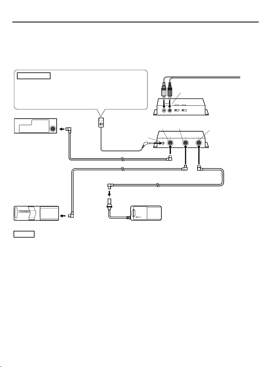
■Components
Switching unit.......................................1
1
Controller (cord length: 5 m) ...............1
2
Connection cable (2 m) ........................1
3
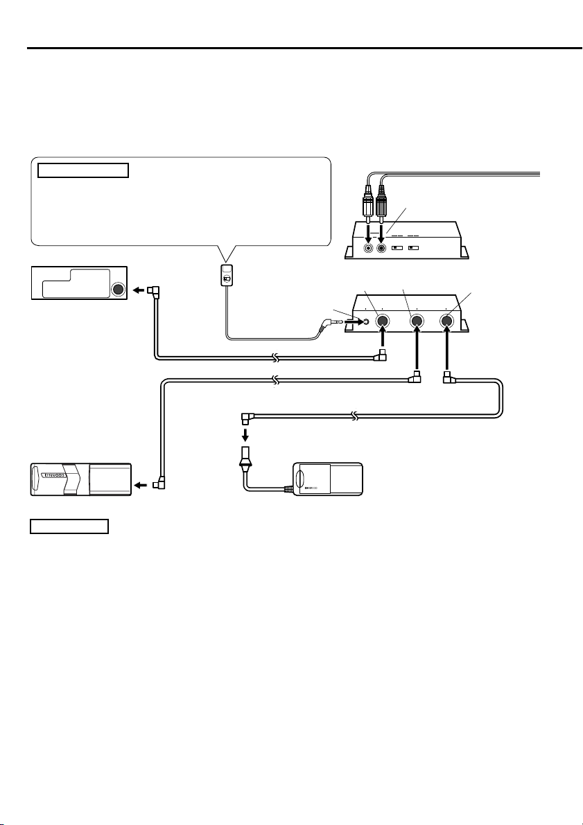
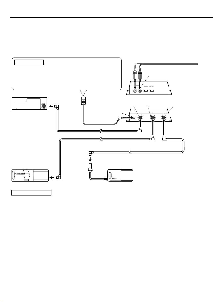
■Connection
2
CAUTION
If you connect a model which can switch between disc
changers 1 and 2 by the centre unit (Unit group B/C/D), the
controller2 must not be connected. If it is connected, the
disc changers may not work properly.
Centre unit
Controller2
CONTROLLER
Connection cable3
Connection cable (supplied with the CD changer)
Connection cable (supplied with the MD changer)
Velcro strip............................................2
4
Self-tapping screw(φ 4 ×16 mm).........2
5
Cable band ............................................1
6
Double-sided adhesive tape ................1
7
To the external unit
AV
IN
TO
IN
TO
H/U
CONTROLLERTOH/U
SWITCH
AUX
AUX
OFF ON
CHANGER 1
TO
CHANGER 1CHANGER 1
SWITCH
ON
TO
TO
PROTOCOL
Switching unit1
(Rear side)
CHANGER 2
TO
Switching unit1
CHANGER 2
(Front side)
TO
CD changer
MD Changer
NOTE
• After connecting the equipment, press the reset button on the centre unit.
• The figure shows that one CD changer and one MD changer are connected. Two CD changers or two
MD changers may be connected.
•A disc player such as the KDC-D300 may be connected instead of the disc changer.
• If you wish to adjust the cable length in accordance with the installation location of the switching unit,
such as in the trunk space, the disc changer extension cable may be used instead of the connection
cable3.
IMPORTANT INFORMATION
This unit is NOT designed to be connected directly to a CD changer that was manufactured and
sold before 1994. If you plan to use such units, please read the following information carefully.
• To control KDC-C600/ KDC-C800/ KDC-601/ KDC-401
A CA-DS100 (sold separately as an optional accessory), along with the extension cord supplied with the
CD changer, are required.
• KDC-C200/ KDC-C300/ KDC-C301/ KDC-C400/ KDC-C100/ KDC-C302/ C205/ C705 and CD changer Manufactured by
Other Companies are not compatible with this Kenwood model.
FAILURE TO FOLLOW THESE INSTRUCTIONS MAY RESULT IN DAMAGE TO THIS UNIT AND/OR THE CD
CHANGER.
2-English
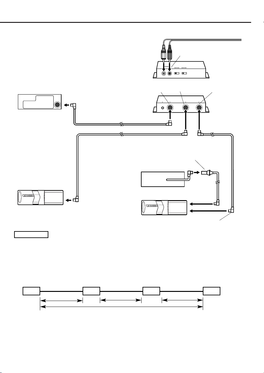
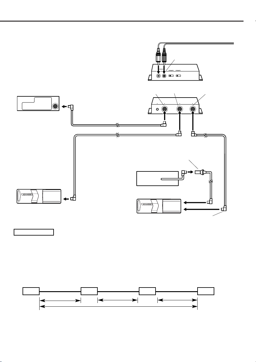
■If you want to connect a stack CD changer
To the external units
AV
IN
IN
SWITCH
SWITCH
AUX
PROTOCOL
AUX
OFF ON
ON
Switching unit1
(Rear side)
Centre unit
TO
H/U
CONTROLLERTOH/U
CHANGER 1
TO
CHANGER 1CHANGER 1
TO
TO
CHANGER 2
TO
TO
CHANGER 2
Switching unit1
(Front side)
Connection cable3
Connection cable (supplied with the Disc changer)
Extension cable (CA-C2E:Optional)
Disc player
Disc changer
Stack CD changer
Connection cable (supplied with the stack CD changer)
2
CAUTION
• Connect it to a centre unit belonging to Group C or Group D.
• Connect the stack CD changer to the terminal labelled TO CHANGER 2.
• The KDC-C810 cannot be connected.
• Up to two disc changers can be connected.
• The O-N switch on the disc changer and the disc player should be set to “N“. If you set it to “O“, the
equipment will not function correctly.
• The total length of the cable between the units should not be more than 13m.
Centre unit
KCA-S210A
Stack CD Changer
Disc Player
Not more than 13m
• If the voltage is low and the internal temperature of the switching unit is low, switching may fail to work
properly in some cases.
• The AUX switch on the stack CD changer should be switched “OFF“ before using the equipment. The
AUX terminal on the KCA-S210A switching unit is the one that should be used.
English-3

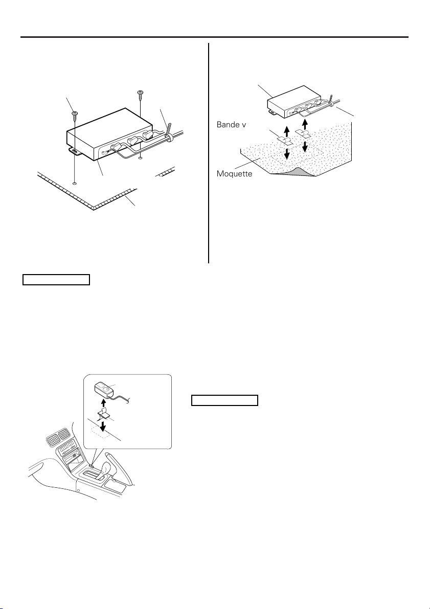
Installation
■Installing the switching unit with a
board in the trunk space
Self tapping screw5
φ
4 × 16 mm)
(
Switching unit1
Board etc.
thickness: 17mm or more
1. Install the switching unit with self-tapping
screws5 (φ4 × 16 mm).
2. Bind the cables with cable band6.
2
CAUTION
• Install the switching unit1 in places that do not obstruct driving.
• Install the switching unit1 in places where it is not touched by the tip of the shoes of a rear seat
passenger.
• Do not install the unit in places where it is exposed to direct sunlight, high heat, or where water may
splash over it.
• Do not place anything on top of the switching unit 1.
Cable band6
■Installing the switching unit on the
carpet under a seat
Switching unit1
Velcro strips4
carpet
1. Remove the backing from the Velcro strips4 and
attach it to the bottom of the switching unit1.
Install the switching unit on the carpet.
2. Bind the cables with cable band6.
Cable band6
■Installing the controller
Double-sided
adhesive
tape7
4-English
Controller2
1. Wipe off the installation location with a cleaning cloth.
2
CAUTION
• Install the controller2 on a flat surface. If it is
installed on a curved surface, the tape adhesion may
weaken and the controller may come off.
• Do not install the controller2 in places (such as on
the dashboard) where it is exposed to direct sunlight
and the temperature becomes high. Otherwise, the
controller2 will become deformed and unusable.
• Install the controller2 in places that do not obstruct
driving. Install the controller2 temporarily and verify
that the handle, shift knob, and side brake can be
operated smoothly.
2. Secure the controller2 in the specified place with the
double-sided adhesive tape7.
Identifying the type of centre unit you intend to connect
AUX
S
OFF
ON
PROTOCOL
SWITCH
O
N
AUX
SWI
OFF
ON
PROTOCOL
SWITCH
O
N
The setting of the PROTOCOL switch and the operation used to switch to AUX sound will
differ depending on the type of centre unit (cassette receiver, CD receiver, and so on) you are
going to connect. Find out which of the following groups your centre unit belongs to, then
consult the relevant section of this manual.
■Group A
This group covers centre units with disc changer control, where the source selection does not allow
you to switch the disc changer between 1 and 2.
■Group B
This group covers centre units with disc changer control, where the source selection allows you to
switch between 1 and 2, where the manual instructs you to set the O-N switch on the disc changer to
“O”, or where the O-N switch operation is not covered.
■Group C
This group covers centre units with disc changer control, where the source selection allows you to
switch between 1 and 2, where the manual instructs you to set the O-N switch on the disc changer to
“N”.
■Group D
This group covers units released on to the market in or after 1999, where the manual covers AUX
mode under source selection.
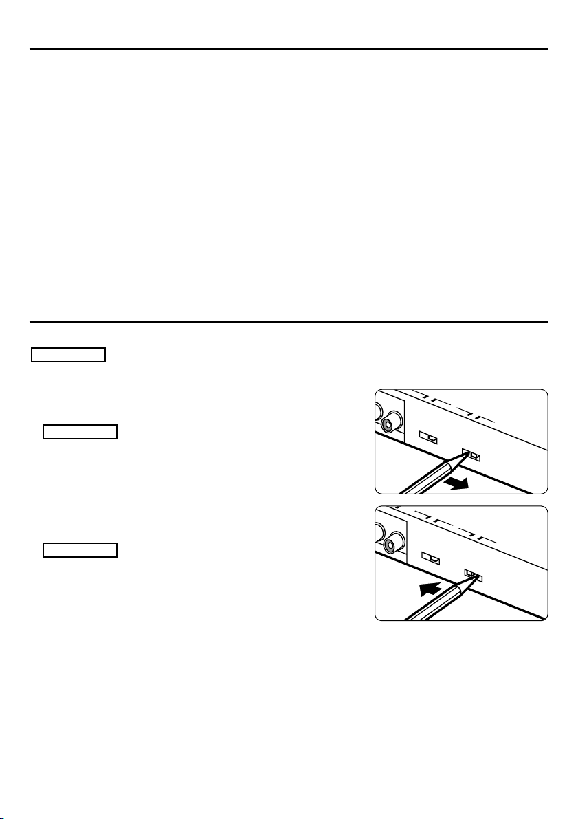
Setting the PROTOCOL switch
You will need to set the PROTOCOL switch according to the centre unit you wish to connect.
2
CAUTION
Turn the centre unit power off before operating the PROTOCOL switch.
■If the unit you are connecting belongs to Group A or
Group B
Set the PROTOCOL switch to the “O” position.
2
CAUTION
If you move the PROTOCOL switch to the “N” position, the
switching unit will become inoperable. (If the disc changer you
have connected has an O-N switch, set it to the “O” position
also.)
■ If the unit you are connecting belongs to Group C or
Group D
Set the PROTOCOL switch to the “N” position.
2
CAUTION
• If you move the PROTOCOL switch to the “O” position,
then even if you have connected a disc changer supporting
CD text, the CD text and the disc name (DNPS) will fail to be
displayed on the centre unit. (If the connected disc
changer has an O-N switch, set it to the “N” position also.)
• If the disc changer you are connecting does not have an ON switch, you will not be able to use the disc name setting
(DNPS) function.
English-5

Switching between disc changers
CHANGER
12
UX
I
AUTO
AUTO
■Unit group A
Select the disc changer to be controlled with the
controller2. When the disc changer mode is
selected with the source button, playing begins.
Disc changer 2
Controller2
ou can switch between
Y
disc changers 1 and 2 by
the switching unit.
Disc changer 1
2
CAUTION
• You cannot change the disc-changer number while a disc changer is playing. To change the disc changer
number, press the source button to stop playing, then change the disc changer number with the
controller2. Select the disc changer mode with the source button.
• When the disc changer number is changed and play begins, the disc changer number data before it was
switched may be shown temporarily on the display of the centre unit.
■Unit groups B/C/D
Each time the SRC button (or CH button) on the centre unit is
pressed, the disc auto changer mode changes between disc
changer modes 1 and 2. When the desired disc changer
number is selected, playing starts.
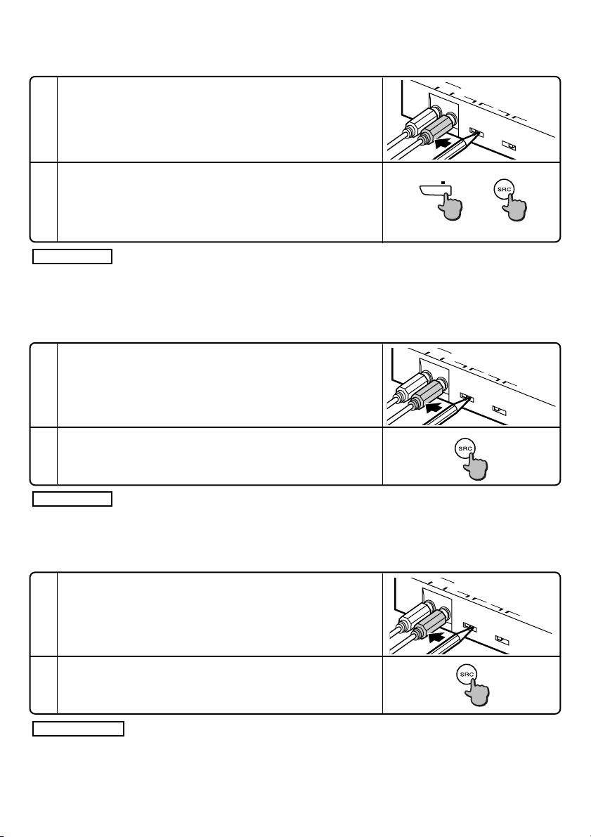
How to switch to AUX sound
■If the unit you are connecting belongs to group A
A
Turn the centre unit power off, or select another source, then
1
set the AUX switch on the switching unit to “ON”.
L
R
SWITCH
ON
AUX
OFF
SWITCH
N
PROTOCOL
O
2
Set the controller switch to “1”
NOTE
If you have only connected the AUX terminal, you will not
need to carry out any further operations.
Select <DISC or CH> on the centre unit.
3
The sound input to the AUX terminal will now be output.
The centre unit display will stay in the following state:
Disc No.=1, Track No.=1, Playing time = 0 min 0 sec
2
CAUTION
TAPE
EJECT
12
CHANGER
PWR
・
CD MD
or
OFF
• If you are going to connect only one disc changer, connect it to the TO CHANGER 2 terminal on the
switching unit.
• If you are going to connect only the AUX terminal of the switching unit, you do not need to connect a
controller.
• After selecting <DISC or CH> on the centre unit, you will not be able to switch to AUX sound, even if
you operate the switching unit or the controller switch.
NOTE
If you want to listen to the sound from the unit connected to the terminal TO CHANGER 1 or 2 on the
switching unit, first either turn off the power to the centre unit, or switch to another source, then turn the
AUX switch to “OFF”. Next, turn the controller switch to “1” or “2”, and select <DISC or CH>.
6-English
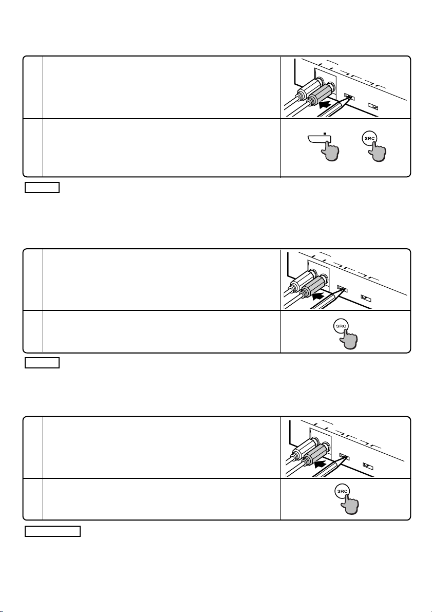
■If the unit you are connecting belongs to group B
UX
I
L
AUX
L
AUX
A
L
MD/CD
R
1-2
CH
SWITCH
ON
AUX
OFF
N
O
or
Either switch the centre unit power off, or select another
1
source, then set the switching unit AUX switch to “ON”.
On the centre unit, select <DISC1 or CH1> .
2
The sound input to the AUX terminal will now be output.
The centre unit display will stay in the following state:
Disc No.=1, Track No.=1, Playing time = 0 min 0 sec
NOTE
If you want to listen to the sound from the unit connected to the TO CHANGER 1 terminal of the
switching unit, first either turn the centre unit power off, or select another source, and then set the AUX
switch to “OFF”, and select <DISC1 or CH1>.
■If the unit you are connecting belongs to group C
Turn the centre unit power off, then set the switching unit
1
AUX switch to “ON”.
On the centre unit, select <DISC2 or CH2>.
2
The sound input to the AUX terminal will now be output.
R
SWITCH
ON
AUX
OFF
SWITCH
N
PROTOCOL
O
SWITCH
PROTOCOL
NOTE
If you want to listen to the sound from the unit connected to the TO CHANGER 2 terminal of the
switching unit, turn the power off, set the AUX switch to “OFF”, and then select <DISC2 or CH2>.
■If the unit you are connecting belongs to group D
Turn the centre unit power OFF, then set the AUX switch on
1
the switching unit to “ON”.
On the centre unit, select <AUX>.
2
The sound input to the AUX terminal will now be output.
2
CAUTION
Leave the AUX switch in the “ON” position. If you move the AUX switch on the switching unit to the
“OFF” setting, <AUX> will not appear when you select the source.
R
SWITCH
ON
AUX
OFF
N
English-7
SWITCH
PROTOCOL
O
Connexion
■Composants
Unité de commutation..................................1
1
Contrôleur (longueur du câble : 5 m) ..........1
2
Câble de raccordement (2 m).......................1
3
■Connextion
2
ATTENTION
Si un modèle dont les changeurs 1 et 2 peuvent être
commutés par l’unité centrale (groupe B/C/D) est
connecté, le contrôleur2 ne doit pas être connecté. Si ce
dernier est connecté, les changeurs de disques
automatique risquent de ne pas fonctionner correctement.
Unité centrale
Contrôleur2
CONTROLLER
Câble de raccordement3
Câble de raccordement (fourni avec le changeur de CD)
Câble de raccordement (fourni avec le changeur de MD)
Bande Velcro .................................................2
4
Vis auto-taraudeuse(φ4 ×16 mm) ...............2
5
Ruban de câble..............................................1
6
Ruban adhésif double face...........................1
7
Vers l’unité externe
AV
IN
TO
TO
H/U
CONTROLLERTOH/U
IN
AUX
SWITCH
AUX
OFF ON
CHANGER 1
TO
CHANGER 1CHANGER 1
TO
TO
SWITCH
PROTOCOL
ON
CHANGER 2
TO
Unité de
commutation1
(Côté arrière)
TO
CHANGER 2
Unité de
commutation1
(Côté avant)
Changeur de CD
Changeur de MD
REMARQUE
• Après avoir raccordé les appareils, appuyer sur la touche de réinitialisation sur l’unité centrale.
• L’illustration montre qu’un changeur de CD et un changeur de MD sont installés. Deux changeurs de CD
et deux changeurs de MD peuvent être connectés.
• Un lecteur de disque tel que le KDC-D300 peut être connecté à la place du changeur de disque.
• Si l’on souhaite ajuster la longueur du câble d’après l’emplacement de l’unité de commutation, tel que
dans le coffre arrière, la rallonge de câble de changeur de CD peut être utilisée au lieu du câble de
raccordement 3.
INFORMATIONS TRES IMPORTANTES
Cet appareil n’est PAS conçu pour être raccordé directement à un changeur de CD fabriqué et
vendu avant 1994. Si un tel appareil doit être utilisé, lire attentivement les informations suivantes.
• Pour contrôler les appareils KDC-C600/ KDC-C800/ KDC-601/ KDC-401
Un CA-DS100 (vendu séparément comme accessoire en option) ainsi que la rallonge de câble fournie
avec le changeur de CD sont nécessaires.
• Les appareils KDC-C200/ KDC-C300/ KDC-C301/ KDC-C400/ KDC-C100/ KDC-C302/ C205/ C705 et les changeurs de CD
fabriqués par d’autres marques ne sont pas compatibles avec ce modèle Kenwood.
SI LES INSTRUCTIONS SUIVANTES NE SONT PAS OBSERVEES, CET APPAREIL OU LE CHANGEUR DE CD
RISQUE D’ETRE ENDOMMAGE.
8-Français
■Si l’on souhaite connecter un changeur à pile de CD
Unité centrale
Câble de raccordement3
Câble de raccordement (fourni avec le changeur de disque)
Câble de rallonge (CA-C2E:Optionnel)
Lecteur de disque
Changeur de disque
Changeur de CD en pile
TO
H/U
CONTROLLERTOH/U
IN
AUX
CHANGER 1
TO
Vers l’unité externe
AV
IN
SWITCH
SWITCH
PROTOCOL
AUX
OFF ON
ON
TO
Unité de
commutation1
(Côté arrière)
TO
CHANGER 2
TO
TO
CHANGER 2
CHANGER 1CHANGER 1
Unité de
commutation1
(Côté avant)
Câble de raccordement (fourni avec le changeur de CD en pile)
2
ATTENTION
• Le connecter à une unité centrale appartenant au groupe C ou D.
• Connecter le changeur à pile de CD au connecteur du changeur 2 étiqueté TO CHANGER 2.
• Le KDC-C810 ne peut pas être connecté.
• Jusqu’à deux changeurs de disque peuvent être connectés.
• Le commutateur O-N du changeur de disque et celui du lecteur de disque doivent être réglés sur “N”.
S’ils sont réglés sur “O”, les appareils ne fonctionneront pas correctement.
• La longueur totale du câble reliant les appareils ne doit pas dépasser 13 m.
Unité centrale
KCA-S210A
Changeur de CD en pile
Lecteur de disque
Pas plus de 13 m
• Si le voltage est faible et la température interne de l’unité de commutation est basse, la commutation
risque de ne pas s’effectuer correctement dans certains cas.
• Le commutateur AUX du changeur à pile de CD doit être positionné sur “OFF” avant d’utiliser les
appareils. C’est le connecteur AUX de l’unité de commutation KCA-S210A qui doit être utilisé.
Français-9
Installation
■Installation de l’unité de
commutation avec une planche dans
■IInstallation de l’unité de commutation
sur la moquette sous un siège
le coffre
Unité de commutation1
Vis auto-taraudeuse5
(
φ
4 × 16 mm)
Unité de commutation1
Planche, etc.
Epaisseur : 17mm ou plus
1. Installer l’unité de commutation avec les vis
auto-taraudeuses5 (φ4 × 16 mm).
2. Lier les câbles avec le ruban de câble6.
2
ATTENTION
• Installer l’unité de commutation1 dans un endroit ne gênant pas la conduite.
• Installer l’unité de commutation1 dans un endroit où elle ne peut être atteinte par l’extrémité des
chaussures d’un passager arrière.
• Ne pas installer l’unité dans des endroits exposés directement au soleil, à la chaleur ou aux
éclaboussures d’eau.
• Ne rien poser sur l’unité de commutation1.
Ruban de
câble6
Ruban de
Bande velcro4
Moquette
1. Retirer la bande de protection des bandes velcro
4 et le fixer sur le fond de l’unité de
commutation1. Installer l’unité de commutation
sur la moquette.
2. Lier les câbles avec le ruban de câble6.
câble6
■Installation du contrôleur
Contrôleur2
Ruban adhésif
double face7
10-Français
1. Nettoyer l’emplacement prévu avec un chiffon.
2
ATTENTION
• Installer le contrôleur2 sur une surface plane. S’il est
installé sur une surface courbe, le ruban adhésif tiendra
mal et le contrôleur risque de se détacher.
• Ne pas installer le contrôleur2 dans des endroits
exposés directement au soleil (tel que le tableau de bord)
ou à haute température car le contrôleur risque de se
déformer et d’être inutilisable.
• Installer le contrôleur2 là où il ne gêne pas la conduite.
Le mettre en place de manière temporaire et vérifier que
toutes les commandes du véhicule sont accessibles sans
aucune interférence.
2. Fixer le contrôleur2 à l’endroit souhaité avec le ruban
adhésif à double face7.

Identification du type d’unité centrale que l’on souhaite connecter
AUX
S
OFF
ON
PROTOCOL
SWITCH
O
N
AUX
SWI
OFF
ON
PROTOCOL
SWITCH
O
N
Le réglage du commutateur PROTOCOL et la façon de commuter sur son AUX seront
différents suivant le type d’unité centrale utilisée (récepteur radio cassette, récepteur radio
lecteur CD, etc.). Déterminer le groupe auquel appartient l’unité centrale et consulter ensuite
la section appropriée de ce manuel.
■Groupe A
Ce groupe comprend les unités centrales disposant d’une commutation de changeurs de disque et
dont la sélection de source ne permet pas la commutation entre les changeurs de disque 1 et 2.
■Groupe B
Ce groupe comprend les unités centrales disposant d’une commutation de changeurs de disque dont la
sélection de source permet la commutation entre 1 et 2 et pour lesquels le manuel indique de placer le
commutateur O-N du changeur de disque sur “O” ou ne couvre pas l’opération du commutateur O-N.
■Groupe C
Ce groupe comprend les unités centrales disposant d’une commutation de changeurs de disque dont la
sélection de source permet la commutation entre 1 et 2 et pour lesquels le manuel indique de placer le
commutateur O-N du changeur de disque sur “N”.
■Groupe D
Ce groupe comprend les appareils mis sur le marché durant ou après 1999 et dont le manuel décrit le
mode AUX dans la section sélection de source.
Réglage du commutateur PROTOCOL
Vous devez regler le commutateur PROTOCOL en fonction de l’unité centrale à laquelle vous
désirez vous connecter.
2
ATTENTION
Avant d’utiliser le commutateur PROTOCOL, couper l’alimentation de l’unité centrale.
■Si l’unité connectée appartient au Groupe A ou B
Réglé le commutateur PROTOCOL sur la position “O”.
2
ATTENTION
Lorsque le commutateur PROTOCOL est placé sur la position
“N”, l’unité de commutation ne fonctionne pas (si le changeur
connecté comporte un commutateur O-N, le placer aussi sur la
position “O”).
■Si l’unité connectée appartient au Groupe C ou D
Réglé le commutateur PROTOCOL sur la position “N”.
2
ATTENTION
• Lorsque le commutateur PROTOCOL est réglé sur “O”, les
changeurs de disque équipés pour lire les textes de CD ne
peuvent afficher ces informations (Titres et DNPS) sur l’unité
centrale (si le changeur connecté comporte un commutateur ON, le placer aussi sur la position “N”).
• Si le changeur de disque connecté ne possède pas de
commutateur O-N, il sera impossible d’utiliser la fonction nom
de CD (DNPS).
Français-11

Commutation entre les changeurs de disques
AUTO
CHANGER
12
UX
I
AUTO
■Unités de groupe A
Sélectionner le changeur de disque devant être
contrôlé par le contrôleur2. Lorsque le mode
changeur de disque est sélectionné avec la touche
Source, la lecture commence.
2
ATTENTION
• Il est impossible de changer de numéro de changeur de disque pendant qu’un changeur de disque est
en lecture. Pour changer de numéro de changeur de disque, appuyer sur la touche Source pour arrêter la
lecture, et ensuite changer le numéro de changeur de disque avec le contrôleur2. Sélectionner le mode
changeur de disque avec la touche Source.
• Lorsque le numéro de changeur de disque a changé et que la lecture commence, le numéro du
changeur de disque antérieur à la commutation peut être affiché temporairement sur l’affichage de
l’unité centrale.
■Unités de groupes B/C/D
Chaque fois que l’on appuie sur la touche SRC (ou la touche
CH) de l’unité centrale, le mode de changeur de disque passe
entre les modes 1 et 2.
Lorsque le numéro de changeur de disque souhaité est
sélectionné, la lecture commence.
Changeur de disque 2
Changeur de disque 1
Contrôleur2
On peut commuter
entre le changeurs de
disque 1 et 2 à travers
l’unité de commutation.
Comment commuter sur le son AUX
■Si l’unité connectée appartient au groupe A
A
Couper d’abord l’alimentation de l’unité centrale ou
1
sélectionner une autre source et ensuite, régler le
commutateur AUX sur marche “ON”
L
R
SWITCH
ON
AUX
OFF
N
O
SWITCH
PROTOCOL
2
Placer le bouton contrôleur sur “1”
REMARQUE
Si seul le connecteur AUX est connecte, il n’est pas
nécessaire d’effectuer d’autres réglages.
Sélectionner le changeur de disque <DISC ou CH> sur l’unité
3
centrale.
Le son envoyé au connecteur AUX sera envoyé aux sorties.
L’unité centrale affichera les informations suivantes :
TAPE
EJECT
12
CHANGER
PWR
・
CD MD
ou
OFF
N° de disque = 1, Piste N° = 1, Durée de lecture = 0 mn 0 sec
2
ATTENTION
• Si un seul changeur de disque doit être utilisé, le raccorder au connecteur TO CHANGER 2 de l’unité de
commutation.
• Si seul le connecteur AUX de l’unité de commutation va être utilisé, il n’est pas nécessaire d’utiliser un
contrôleur.
• Après avoir sélectionné le changeur de disque <DISC ou CH> sur l’unité centrale, il est impossible de
sélectionner son AUX, même en agissant sur l’unité de commutation ou le bouton contrôleur.
REMARQUE
Pour écouter le son de l’unité raccordée au connecteur TO CHANGER 1 ou 2 sur l’unité de commutation,
d’abord couper l’alimentation de l’unité centrale ou sélectionner une autre source et tourner ensuite le
commutateur AUX sur “OFF”. Puis, tourner le commutateur de contrôleur sur “1” ou “2” et sélectionner
changeur de disque <DISC ou CH>.
12-Français
■Si l’unité connectée appartient au groupe B
UX
I
L
AUX
L
AUX
A
L
MD/CD
R
1-2
CH
ou
SWITCH
ON
AUX
OFF
N
PROTOCOL
O
Couper d’abord l’alimentation de l’unité centrale ou
1
sélectionner une autre source et ensuite, régler le
commutateur AUX sur “ON”.
Sur l’unité centrale, sélectionner <DISC1 ou CH1>.
2
Le son envoyé au connecteur AUX sera envoyé aux sorties.
L’unité centrale affichera les informations suivantes :
N° de disque = 1, Piste N° = 1, Durée de lecture = 0 mn 0 sec
REMARQUE
Pour écouter le son de l’unité raccordée au connecteur TO CHANGER 1 sur l’unité de commutation,
d’abord couper l’alimentation de l’unité centrale ou sélectionner une autre source et tourner ensuite le
commutateur AUX sur “OFF”. Puis, tourner le commutateur de contrôleur sur “1” ou “2” et sélectionner
changeur de disque <DISC1 ou CH1>.
■Si l’unité connectée appartient au groupe C
Couper d’abord l’alimentation de l’unité centrale “OFF” et
1
ensuite, régler le commutateur AUX sur “ON”.
Sur l’unité centrale, sélectionner <DISC2 ou CH2>.
2
Le son envoyé au connecteur AUX sera envoyé aux sorties.
R
SWITCH
ON
AUX
OFF
SWITCH
N
PROTOCOL
O
SWITCH
REMARQUE
Pour écouter le son de l’unité raccordée au connecteur TO CHANGER 2 sur l’unité de commutation,
d’abord couper l’alimentation de l’unité centrale, puis tourner le commutateur AUX sur “OFF” et ensuite
sélectionner changeur de disque <DISC2 ou CH2>.
■Si l’unité connectée appartient au groupe D
Couper d’abord l’alimentation de l’unité centrale et ensuite,
1
régler le commutateur AUX sur “ON”.
Sur l’unité centrale, sélectionner <AUX>.
2
Le son envoyé au connecteur AUX sera envoyé aux sorties.
2
ATTENTION
Laisser le commutateur AUX sur la position marche “ON”. Si le commutateur AUX de l’unité de
commutation est laissé sur la position “OFF”, <AUX> n’apparaîtra pas lorsque la source sera
sélectionnée.
R
SWITCH
ON
AUX
OFF
SWITCH
N
PROTOCOL
O
Français-13
Anschlüsse
■Komponenten
Schalteinheit..................................................1
1
Steuergerät (Kabellänge: 5 m) .....................1
2
Anschlußkabel (2 m) .....................................1
3
■Anschlüsse
2
ACHTUNG
Wenn Sie ein Modell anschließen, das über die Zentraleinheit
(Einheitsgruppe B/C/D) zwischen den Disc-Wechslern 1 und 2
umschalten kann, ist der Anschluß des Steuergerätes2 nicht
erforderlich. Wenn das Steuergerät 2 angeschlossen ist, arbeiten die
automatischen Disc-Wechsler möglicherweise nicht ordnungsgemäß.
Zentraleinheit
Steuergerät2
CONTROLLER
Anschlußkabel3
Anschlußkabel (Lieferumfang des CD-Wechslers)
Anschlußkabel (Lieferumfang des MD-Wechslers)
Velcro-Strip....................................................2
4
Blechschraube(φ4 ×16 mm) ........................2
5
Kabelbinder....................................................1
6
Doppelseitiges Klebeband............................1
7
TO
TO
H/U
CONTROLLERTOH/U
IN
AUX
AUX
CHANGER 1
TO
An das externe Gerät
AV
IN
SWITCH
SWITCH
PROTOCOL
OFF ON
ON
TO
Schaltgerät1
(Rückseite)
TO
CHANGER 2
TO
TO
CHANGER 2
CHANGER 1CHANGER 1
Schaltgerät1
(Vorderseite)
CD-Wechsler
MD-Wechsler
ANMERKUNGEN
• Drücken Sie nach Anschluß des Gerätes die Reset-Taste an der Zentraleinheit.
• Auf der Abbildung ist sowohl ein CD-als auch ein MD-Wechsler angeschlossen. Möglich ist auch der
Anschluß von zwei CD-Wechslern bzw. zwei MD-Wechslern.
• Anstelle des Disc-Wechslers ist auch der Anschluß des KDC-D300 möglich.
• Wenn Sie die Kabellänge der Schalteinheit aufgrund der Gegebenheiten des Installationsortes ändern
möchten, wie z.B. bei der Installation im Kofferraum, sollten Sie an Stelle des Anschlußkabels3
möglicherweise das Verlängerungskabel des Disc--Wechslers benutzen.
WICHTIGE HINWEISE
Dieses Gerät ist NICHT für den direkten Anschluß an einen vor 1994 hergestellten und verkauften
CD-Wechsler ausgelegt. Wenn Sie die Benutzung derartiger Geräte beabsichtigen, lesen Sie sich
bitte die nachfolgenden Informationen sorgfältig durch.
• Zur Steuerung von KDC-C600/ KDC-C800/ KDC-601/ KDC-401
Ein CA-DS100 (als separates Zubehör im Handel erhältlich) sowie das zum Lieferumfang des CDWechslers gehörende Verlängerungskabel sind erforderlich.
• KDC-C200/ KDC-C300/ KDC-C301/ KDC-C400/ KDC-C100/ KDC-C302/ C205/ C705 sowie CD-Wechsler von anderen
Herstellern sind mit diesem Kenwood-Modell nicht kompatibel.
EINE NICHTBEACHTUNG DIESER HINWEISE KANN ZU BESCHÄDIGUNGEN DIESES GERÄTES
UND/ODER DES CD-WECHSLERS FÜHREN.
14-Deutsch
 Loading...