


Kenwood KCH-20R, NX-5700(B), NX-5800(B), NX-5000, NX-5700 USER MANUAL [es]
...KCH-20R
USER MANUAL
MODE D’EMPLOI MANUAL DEL USUARIO
B5A 0605-00

REMOTE CONTROL HEAD
KCH-20R
USER MANUAL
•SDTM and microSDTM are trademarks of SD-3C, LLC in the United States. and/ or other countries.
•The Bluetooth® word mark and logos are registered trademarks owned by Bluetooth SIG, Inc. and any use of such marks by JVC KENWOOD
Corporation is under license. Other trademarks and trade names are those of their respective owners.
Firmware Copyrights
The title to and ownership of copyrights for firmware embedded in KENWOOD product memories are reserved for JVC KENWOOD Corporation.

PRECAUTIONS
•Do not disassemble or modify the unit for any reason.
•Do not expose the unit to long periods of direct sunlight, nor place it close to heating appliances.
•Do not place the unit in excessively dusty and/or humid areas, nor on unstable surfaces.
•If you detect an abnormal odor or smoke coming from the unit, disconnect the power from the unit immediately. Contact your KENWOOD service center or dealer.
•Do not attempt to configure the transceiver while driving; it is too dangerous.
•Do not use options not specified by KENWOOD.
•For passenger safety, install the unit securely using the supplied mounting bracket and screw set so the unit will not break loose in the event of a collision.
•Always turn off the power before installing optional accessories.
•When using the KCH-20R, refer to the “NOTICES TO THE USER” and
“PRECAUTIONS” in the USER GUIDE of Mobile Transceiver of NX-5000 series. If
the warnings (


 ) are not observed, there may be the possibility to have any malfunction. In this case, press and hold the Power Switch for 5 seconds or more. If the malfunction persists, ask your dealer.
SUPPLIED ACCESSORIES |
|
A Mounting bracket........................................................................................................... |
1 |
B Mounting screw............................................................................................................. |
2 |
C Screw set (5 x 16 mm self-tapping screw x 4, Spring washer x 4, Flat washer x 4)..... |
1 |
D Microphone cable holder............................................................................................... |
1 |
E Pan head sems screw (M3 x 8 mm).............................................................................. |
1 |
F PF name plates (the A, B and C name plate has been attached)................................. |
1 |
F
|
C |
A |
E |
|
|
|
|
|
|
E |
|
D |
D |
|
|
|
|
Microphone |
|
|
cable |
B |
|
2

REPLACING THE PF NAME PLATE
You can reconfigure the PF name plates at any time.
1Remove the current PF name plate from the function key using a fine-tipped tool.
2Punch out the PF name plate card, and insert the plate onto the relative function key.

 Name plate
Squeeze and insert the plate
INSTALLING THE microSD MEMORY CARD
1Open the Cap.
2Insert the microSD memory card.
•Insert the microSD memory card with its terminal side facing the same side as the front of the panel.
•Insert the microSD memory card until it clicks into place.
•To remove the microSD memory card, push the card inwards once, then pull it out straight.
microSD 


 memory card


Cap 


Note:
microSD memory cards (Class 2 or higher) and microSDHC memory cards (Class 2 or higher) can be used.
SDXC memory cards cannot be used.
This transceiver is not guaranteed to operate with all microSD memory cards.
(Operations are confirmed on memory cards for the following brands: SanDisk, TOSHIBA and Panasonic.)
Use the microSD memory card within the allowable operating temperature.
Do not remove the microSD memory card or turn off this transceiver while the microSD memory card is being accessed.
The waterproof performance is not guaranteed if the microSD memory card slot cap is not fit into place.
Make sure your hands are clean before opening the microSD memory card slot cap.
Compensation Disclaimer
Data stored on the microSD memory card may be altered or lost due to problems with this transceiver.We do not accept liability in respect of the data stored on your microSD memory card, failure to save the data properly, loss of data, and any direct or indirect damages.
3

ORIENTATION
OPERATION PANEL
A B C D E
F

G


H
I J K L M
A[ ] (Power) switch
Press to switch the transceiver ON or OFF.
B [ ] / [ ] keys
Press to activate its programmable function.
C 4-way D-pad
Press to activate its programmable function.
DPF keys <with Name Plate>
Press to activate its programmable function.
EAuxiliary (orange) key
Press to activate its programmable function.
FIllumination sensor
Sensor for Auto Dimmer Function.
GTX Indicator
Lights red while transmitting.
HBusy / Status indicator
Lights green while receiving. The indicator lights in different colors to indicate the current status of the transceiver.
IMicrophone jack
Insert the microphone plug into this jack.
J[ ] / [
] / [ ] / [
] / [ ] / [
] / [ ] / [
] / [ ] / [
] / [ ] keys
Press to activate their programmable functions.
K[  ] / [
] / [  ] keys
Press to activate their programmable functions.
LVOL (Volume) control
Rotate clockwise to increase the volume level. Rotate counterclockwise to decrease the volume level.
4
MCH (Channel) control
Rotate this control to activate its programmable function. (The default setting is Channel Select.)
For details on programming functions to the keys on your transceiver, please contact your dealer or refer to the instruction manual available from the following URL.
http://manual2.jvckenwood.com/en_contents/search/
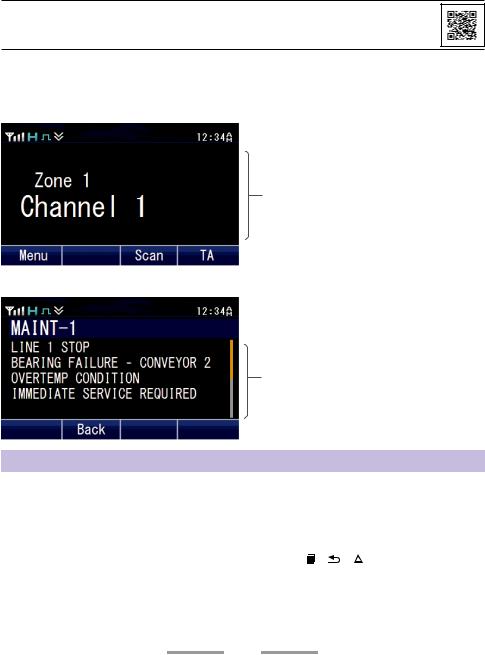
DISPLAY
Basic Frame
 Function Indicator Area
Main Area
 Key Guide Area
Message Frame
 Messenger Area
Message Area
Display Area |
Description |
|||
|
|
|
|
|
Function Indicator Area |
Displays the various function indicators, signal strength |
|||
indicator and clock. |
||||
|
|
|
|
|
Main Area |
Displays the information of the transceiver such as Channel |
|||
number and Zone number. |
||||
|
||||
|
|
|
|
|
Key Guide Area |
Displays the key functions for [ ], [ ], [ ], and [ |
|
] keys. |
|
|
||||
|
|
|
|
|
Messenger Area |
Displays the Caller ID/Name. |
|||
|
|
|
|
|
Message Area |
Displays the message texts. |
|||
|
|
|
|
|
5

FUNCTION INDICATOR
Indicator |
Description |
Displays the signal strength.
The channel is using high transmit power.
The channel is using medium transmit power.
The channel is using low transmit power.
In Digital mode (Digital Channel)
In Analog mode (Analog Channel)
In Digital mode (Mixed Channel)
In Analog mode (Mixed Channel)
The Bluetooth function is activated. Blinks in the process of turning on Bluetooth.
Connected to Bluetooth device.
The GPS position is determined. Blinks when the GPS is unable to determine the position.
Non-priority Scan or Voting/Site Roaming is in progress. Blinks when the scan is paused. (green icon)
Priority Scan is in progress. Blinks when the scan is paused. (red icon)
Indicates Priority channel 1 or Priority Monitor ID 1.
Indicates Priority channel 2 or Priority Monitor ID 2.
Indicates Priority Monitor ID 3.
Indicates Priority Monitor ID 4.
The current channel is added to the scanning sequence.
The current Zone is added to the Multi-Zone scanning sequence.
The Scrambler function is activated.
The Encryption function is activated. Blinks when receiving an encrypted carrier.
The Encryption (AES) function is activated. Blinks when receiving an encrypted carrier.
The Encryption (DES) function is activated. Blinks when receiving an encrypted carrier.
6
, NX-5800(B), NX-5000, NX-5700 USER MANUAL")
Indicator |
Description |
The Talk Around function is activated.
The Monitor or Squelch Off is activated.
The External Speaker is activated.
The External Speaker (Internal + External) is activated.
The Noise Reduction function is activated. Blinks when Noise Reduction is functioning.
Blinks when an incoming call matches your Optional Signaling.
A message is stored in memory. Blinks when a new message has arrived.
The microSD memory card is recognized.
The microSD memory card is not recognized.
The VOX function is activated.
The Site Lock function is activated.
The Broadcast Call function is activated.
The Surveillance function is activated.
The selected group is programmed as telephone IDs.
The Horn Alert function is activated.
The Public Address function is activated.
AUX A is activated.
AUX B is activated.
AUX C is activated.
The Lone Worker function is activated.
The Compander function is activated.
The Operator Selectable Tone function is activated.
Blinks during Auto Recording.
The Key Lock function is activated.
7
 Loading...