


KC-993
Table of contents
 Loading...
m
CONTROL AMPLIFIER
KC-993
INSTRUCTION MANUAL
KENWOOD CORPORATION
B60-1054-00 di) (K. P, M,X,Y)
Introduction
Your choice of this product indicates that you are a devotee
to exceilence in sound reproduction.
We appreciate your patronage and take pride in the long tradi
tion of quality components that our company represents.
So that you can get the most ou"t of your unit, we suggest that
you take the time to read through this manual before you hook
up and operate your system. This will acquaint you with oper
ating features and system-connection considerations, so that
your listening pleasure will be enhanced right from the start.
You will notice that in all aspects of planning, engineering,
styling, operating convenience and adaptability we have sought
to anticipate your needs and desires.
Keep this manual handy for future reference.
For your records
Record the serial number, found on the back of the unit, in
the spaces designated on the warranty card, and in the space
provided below. Refer to the mode! and serial numbers
whenever you cal! upon your dealer for information or service
on this product.
Model
_______________
Serial Number
_____________________
Unpacking
Unpack the unit carefully and make sure that all accessories
are put aside so they will not be lost.
Examine the unit for any possibility of shipping damage. If
your unit is damaged or fails to operate, notify your dealer
immediately, if your unit was shipped to you directly, notify
the shipping company without delay. Only the consignee (the
person or company receiving the unit) can file a claim against
the carrier for shipping damage.
We recommend that you retain the original carton and pack
ing materials for use should you transport or ship the unit in
the future.
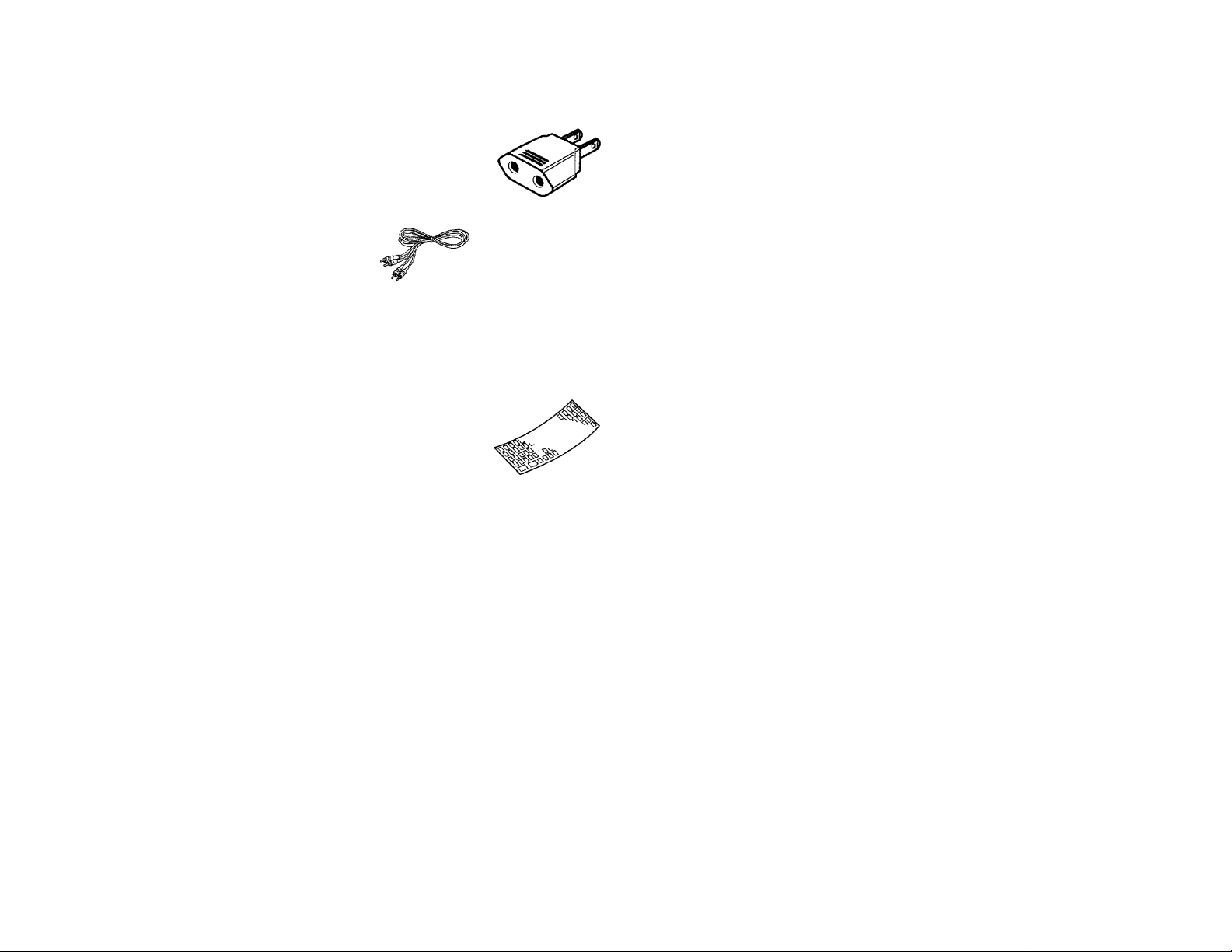
Accessories
• AC plug adaptor
....
..............
1
(Except for some areas)
For the unit with a European
AC plug in areas other than
Europe.
Audio cord ..
Remote control unit...... 1 • Batteries (R03/AAA).... 2
Overlay sheet ...............1
Contents
Introduction
.
.......
.
...........
.
.....................
...........
....................2
A Before applying power
..............
.
.............
.
........................
3
A Safety precautions
..............
.
......
................
......................
3
A IMPORTANT SAFEGUARDS
..................
.
............
.
........
...4
Controls and indicators
...........
.
...........
.
................................
6
System connections
...........................................
.........
.........
7
System control operation
_
__________
__
________
_
___
8
Caution: Read the pages marked A carefully to ensure safe operation.
.....
.
....
.
...................
..10operating instructions
.............
.
.......
.
......
..................
Operation for components connected
to the TAPE 2/ADAPTOR jacks...................................13
Graphic equalizer operation
.........
.
......................
.............14
Remote control operation ....
................................
............17
In case of difficulty
.........................
..................
.
.........
.
......
22
A Specifications
...........................................................
23
Before applying power
A
Caution: Read this page carefully to ensure safe operation.
For the U.S.A. and Canada
Important!
Units shipped to the U.S.A. and Canada are designed for
operation on 120 volts AC only.
CAUTION; TO PREVENT ELECTRIC SHOCK DO NOT USE
THE AC PLUG WITH AN EXTENSION CORD, RECEPTACLE OR
OTHER OUTLET UNLESS THE BLADES CAN BE FULLY
INSERTED TO PREVENT BLADE EXPOSURE.
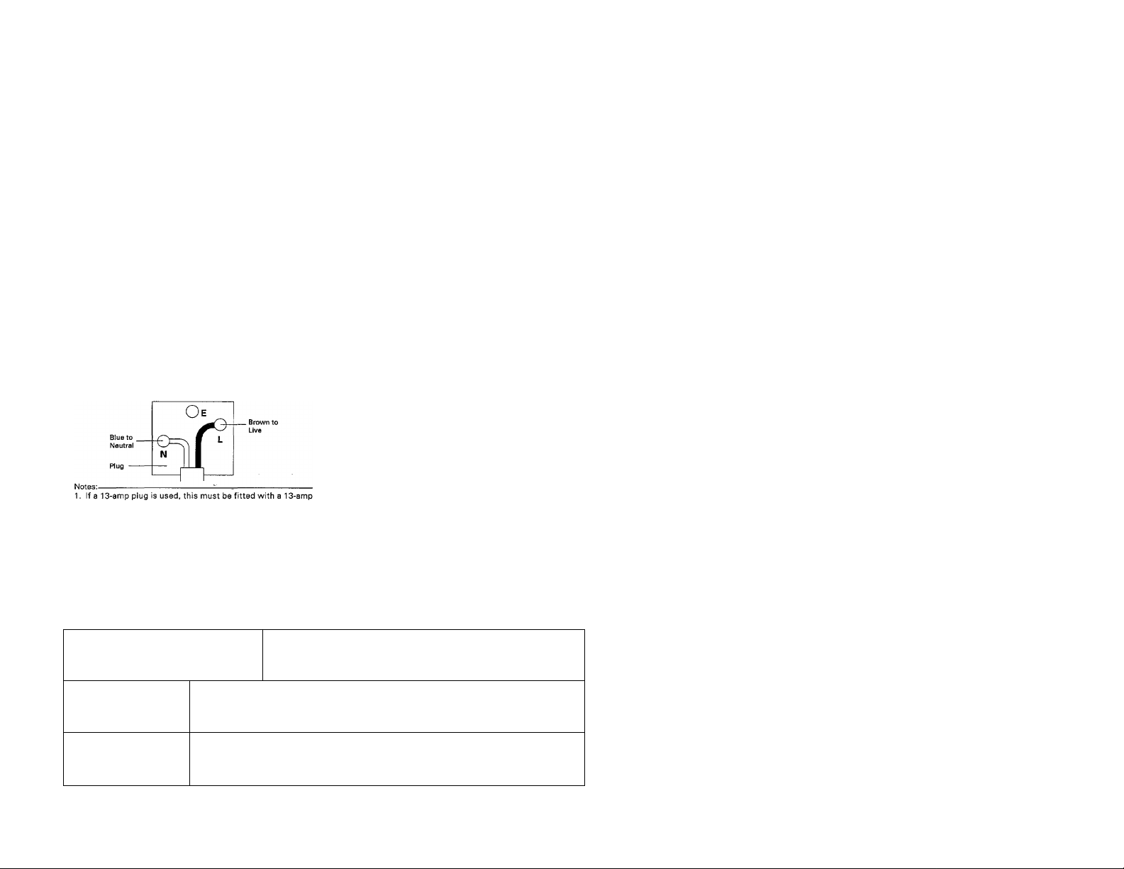
For the United Kingdom
Important I
Units shipped to the U.K. are designed for operation on 240
volts AC only.
The mains plug must be removed from the wall socket prior to
any internal examination.
The wires in this mains lead are coloured in accordance with the
following code;
Blue
..........
.
..............
—...............
_____
Neutral
Brown
...............
.
—
_
______
_
______
_
__
Li-\te
The wires in this mains lead must be connected to the terminals
in the plug as follows:
Wire colour Plug terminal marking
Blue
.............
.
........
.
...................
.
.........
N or Black
Brown
...........
.
.......
..
.....................
........ L or Red
fuse.
2. If a 3-pin plug with earthing contact is used, no wire must be
connected to the E terminal.
For Australia and Europe
importanti
Units shipped to Australia are designed for operation on 240 V AC
only.
Units shipped to Europe are designed for operation on 230 V AC only.
For other countries
Important!
Units shipped to countriesother than the above countries are equipped
with an AC voltage selector switch on the rear panel. Refer to the
following paragraph for the proper setting of this switch.
AC voltage selection
This unit operates on 110 -120 or 220 - 240 volts AC, The AC voltage
selector switch Type A or Type B on the rear panel is set to the
voltage that prevails in the area to which the unit is shipped. Before
connecting the power cord to your AC outlet, make sure that the
setting position of this switch matches your line voltage. If not it
must be set to your voltage in accordance with the following
direction.
AC voltage selector switch
Type A
TypeB
AC110" ■
120 V~
AC 220-
240 V-
AC НО
ШУ-
AC220V- AC230 - 240V-
Move switch lever to match your line voltage with
a small screwdriver or other pointed tool.
Our warranty does not cover damage caused by excessive line
voltage due to improper setting of the AC voltage selector switch.
Safety precautions
WARNING; TO PREVENT FIRE OR ELECTRIC SHOCK, DO NOT EXPOSE THIS APPLIANCE
TO RAIN OR MOISTURE.
CAUTION: TO REDUCE THE RISK OF ELECTRIC SHOCK, DO NOT REMOVE
COVER (OR BACK). NO USER-SERVICEABLE PARTS INSIDE, REFER SER
VICING TO QUALIFIED SERVICE PERSONNEL.
A
THE LIGHTNING FLASH WITH ARROWHEAD SYMBOL. WITHIN AN EQUILATERAL TRIANGLE,
IS INTENDED TO ALERT THE USER TO THE PRESENCE OF UNINSULATED "DANGEROUS VOL
TAGE" WITHIN THE PRODUCT'S ENCLOSURE THAT MAY BE OF SUFFICIENT MAGNITUDE
TO CONSTITUTE A RISK OF ELECTRIC SHOCK TO PERSONS.
A
THE EXCLAMATION POINT WITHIN AN EQUILATERAL TRIANGLE IS INTENDED TO ALERT THE
USER TO THE PRESENCE OF IMPORTANT OPERATING AND MAINTENANCE (SERVICING) IN
STRUCTIONS IN THE LITERATURE ACCOMPANYING THE APPLIANCE.
KC-993 (En) 3
IMPORTANT SAFEGUARDS
A Caution: Read this page carefully to ensure safe operation.
Please read all of the safety and operating instructions
before operating this unit. For best results, follow all
warnings placed on the unit and adhere to the operating
and use instructions. These safety and operating
instructions should be retained for future reference.
1. Power sources - The unit should be connected to
a power supply only of the type described In the
operating instructions or as marked on the
appliance.
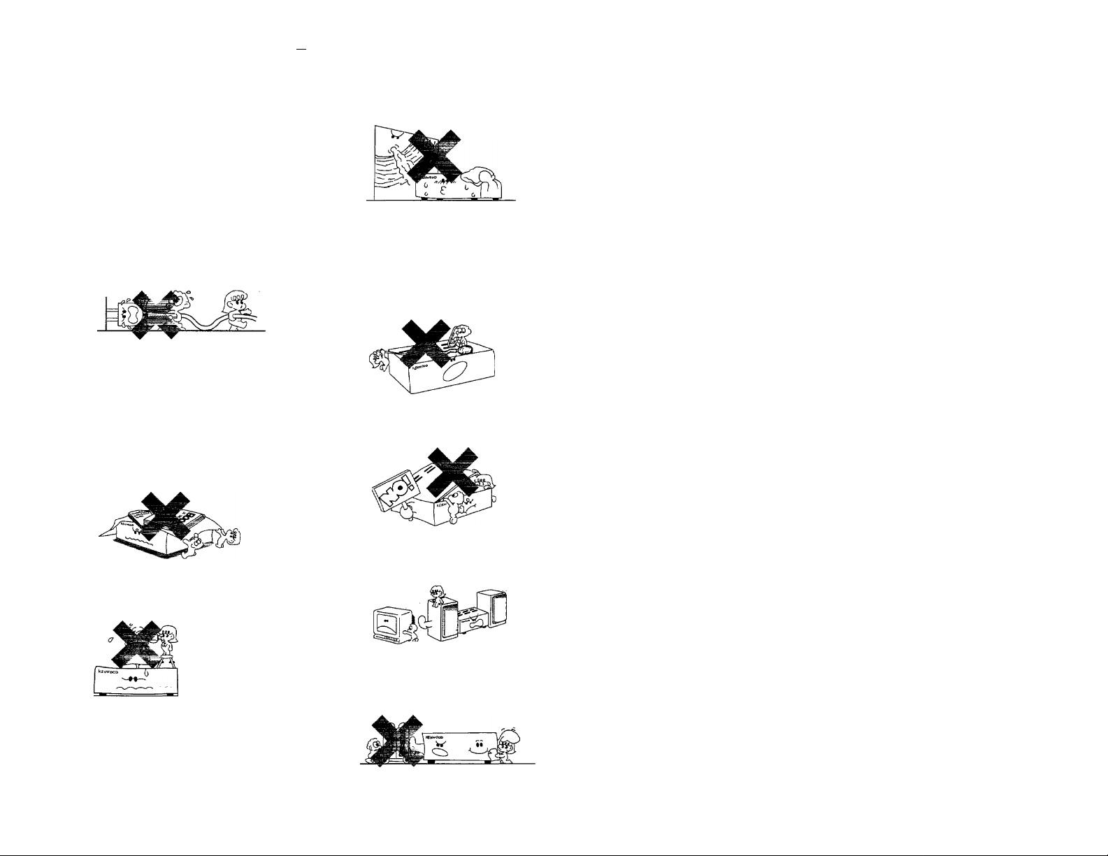
2. Power-cord protection - Power-supply cords
should be routed so that they are not likely to be
walked on or pinched by Items placed upon or
against them, pay particular attention to cords at
plugs, convenience receptacles, and the point
where they exit from the unit.
Never pull or stretch
the cord.
3. Grounding or polarization - The precautions
should be taken so that the grounding or polarization
means of this unit is not defeated.
4. Ventilation - The unit should be situated so that
its location or positibri^does not interfere with its
proper ventilation.
To maintain good ventilation, do not put records or
a table-cloth on the unit. Place the unit at least 10
cm away from the walls.
Do not use the unit on a bed, sofa, rug or similar
surface that may block the ventilation openings.
Water and moisture-The unit should not be used
nearwater-for example, neara bathtub, washbowl,
kitchen sink, laundry tub, in a wet basement, or
near a swimming pool, etc.
6. Temperature - The unit may not function properly
if used at extremely low, or freezing temperatures.
The ideal ambient temperature is above +5°C
(41°F).
7.Heat - The unit should be situated away from heat
sources such as radiators, heat registers, stoves,
or other units (including amplifiers) that produce
heat.
Electric shock - Care should be taken so that
objects do not fail and liquid is not spilled into the
enclosure through openings. If a metal object,
such as a hair pin or a needle, comes into contact
with the inside of this unit, a dangerous electric
shock may result. For families with children, never
permit children to put anything, especially metal,
inside this unit.
9. Enclosure removal - Never remove the enclosure.
If the internal parts are touched accidentally, a
serious electric shock might occur.
10.Magnetic fields- Keep the unit away from sources
of magnetic fields such as TV sets, speaker
systems, radios, motorized toys or magnetized
objects.
11.Cleaning - Do not use volatile solvents such as
alcohol, paint thinner, gasoline, or benzine, etc. to
clean the cabinet. Use a clean dry cloth.
A Caution : Read this page carefully to ensure safe operation.
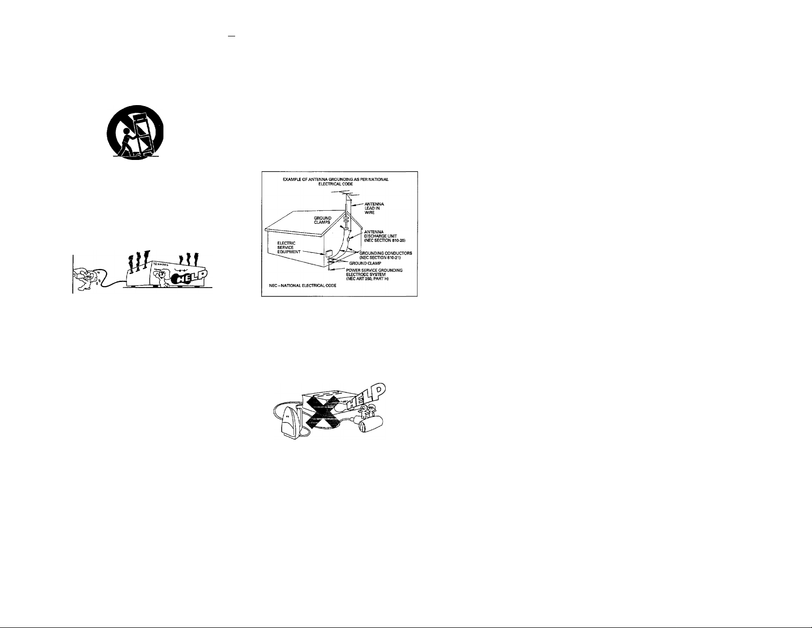
12.Carts and stands - An appliance and cart
combination should be moved with care. Quick
stops, excessive force, and uneven surfaces may
cause the appliance and cart combination to
overturn.
17.Outdoor antenna grounding - If an outside an
tenna is connected to the receiver, be sure the an
tenna system is grounded so as to provide some
protection against voltage surges and built up static
charges. Section 810 of the National Electrical
Code, ANSI/NFPA 70, provides information with
respect to proper grounding of the mast and
supporting structure, grounding of the lead-in wire
to an antenna discharge unit, size of grounding
conductors, location of antenna-discharge unit,
connection to grounding electrodes, and
requirements for the grounding electrode. See
Figure.
13. Nonuse periods ~ The power cord of the unit
should be unplugged from the outlet when left un
used for a long period of time.
14. Abnormal smell - If an abnormal smell or smoke
is detected, immediately turn the power OFF and
puli out the power cord. Contact your dealer or
nearest service center.
POWER OFF!
15.Damage requiring service - The unit should be
serviced by qualified service personnel when:
A. The power-supply cord or the plug has been
damaged; or
B. Objects have fallen, or liquid has been spilled
into the unit; or
C. The unit has been exposed to rain; or
D. The unit does not appear to operate normally or
exhibits a marked change in performance; or
E. The unit has been dropped, or the enclosure
damaged.
IG.Servicing - The user should not attempt to
service the unit beyond that described in the
operating instructions. All other servicing should
be referred to qualified service personnel.
18. Power lines - An outdoor antenna should be lo
cated away from power lines.
19. AC outlets - Do not connect other audio
equipment with a power consumption larger than
that specified to the AC outlet on the rear panel.
Never connect other electrical units, such as an
iron or toaster, to it to prevent fire or electric
shock.
Notes:
1. Item 3 is not required except for grounded or polarized equipment.
2. Item 17 and 18 are not required except for units provided with antenna terminals.
3. Item 17 complies with UL in the U.S.A.
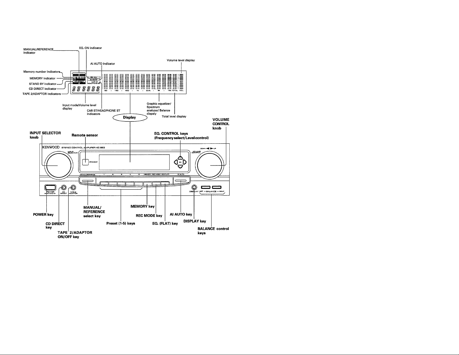
Controls and indicators
STAND BY mode of POWER key
When the power cord of this system is plugged into an AC outlet, the
STAND BY indicator lights up regardless of the ON/OFF setting of the
POWER switch. This indicates that a small amount of current is being
supplied to the unit to back up the memory contents. This mode is
referred to as the Stand By mode. While the STAND BY indicator is lit,
the power of the system can be switched ON/OFF from the remote
control unit.
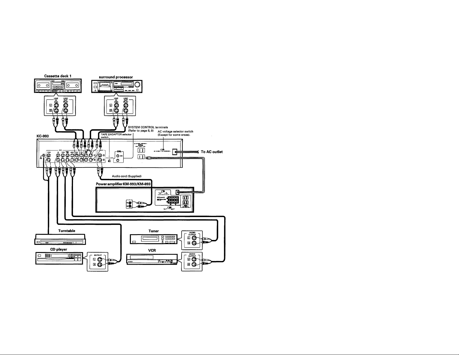
System connections
Make connections as shown below. When connecting the related system components, refer also to the instruction
manuals of the related components.
Do not plug in the power lead until ail connections are completed.
Cassette deck 2 or
Notes;
1. Connect all cords firmly. If connections are loose, there could be loss sound or noise produce.
2. When plugging and unplugging connection cords, be sure to first remove the power cord from the AC outlet. Plugging/unplugging connection
cords without removal of the power cord can cause malfunctions or damage to the unit,
3. Do not connect up a power source which is larger than that indicated on the socket at the rear of the unit.
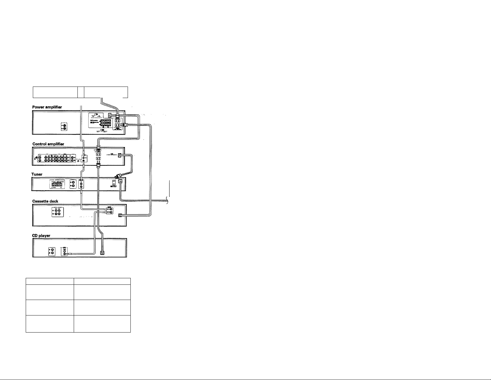
System control operation
For the system control of KENWOOD system components, connect them using the system control cords as shown in the
illustration below.
If the power cords are connected as shown in the illustration, the power of the whole system can be switched ON/OFF from
the POWER key on the control amplifier.
(For the audio cord connection, please refer to "System connections".}
Turntable
JL
Connect the power cord of the
amplifier to the UNSWITCHED AC
outlet of the tuner.
To AC outlet
AC outlet
Unit destination
Shape of the AC outlet
U.S.A., Canada
and U.S. Military
u III
Australia
o
Other countries
»
SWITCHED AC outlet
The power of the component connected to this kind of AC outlet is
switched ON/OFF in interlocked operation with the POWER key on the
main unit on which the AC outlet is installed.
Note;
Do not connect the system control cord to the cassette deck connected to the TAPE 2/ADAPTOR jacks.
8 KC-993 (En)
Loading...