


CMOS-300
CMOS-200
UNIVERSAL MULTI-VIEW CAMERA/ UNIVERSAL REAR VIEW CAMERA
INSTRUCTION MANUAL
CAMÉRA MULTI-VUES UNIVERSELLE/ CAMÉRA DE RECUL UNIVERSELLE
MODE D’EMPLOI
UNIVERSAL MULTIVIEW-KAMERA/ UNIVERSAL RÜCKFAHRKAMERA
BEDIENUNGSANLEITUNG
UNIVERSELE MULTIVIEWCAMERA/ UNIVERSELE ACHTERUITRIJCAMERA
GEBRUIKSAANWIJZING
TELECAMERA MULTIVISIONE UNIVERSALE/ TELECAMERA PER RETROMARCIA UNIVERSALE
ISTRUZIONI PER L’USO
CÁMARA DE MULTIVISIÓN UNIVERSAL/ CÁMARA DE VISTA TRASERA UNIVERSAL
MANUAL DE INSTRUCCIONES
CÂMARA MULTIVISÃO UNIVERSAL/ CÂMARA TRASEIRA UNIVERSAL
MANUAL DE INSTRUÇÕES
Take the time to read through this instruction manual.
Familiarity with installation and operation procedures will help you obtain the best performance from your new Universal Camera.
For your records
Record the serial number, found on the back of the unit, in the spaces designated on the warranty card, and in the space provided below. Refer to the model and serial numbers whenever you call upon your Kenwood dealer for information or service on the product. Model CMOS-300/CMOS-200 Serial number
US Residence Only
Register Online
Register your Kenwood product at www.Kenwoodusa.com
© B64-4756-18/01 (W)

Before Use/ Installation Procedure
2WARNING
To prevent injury or fire, take the following precautions:
•To prevent a short circuit, never put or leave any metallic objects (such as coins or metal tools) inside the unit.
•Installation and wiring of this product require specialist skill and experience. To assure your safety, please request a specialist technician to install the unit.
2CAUTION
To prevent damage to the product, take the following precautions:
•Make sure to ground the unit to a negative 12V DC power supply.
•When replacing a fuse, only use a new fuse with the prescribed rating. Using a fuse with the wrong rating may cause your unit to malfunction.
•Do not use your own screws. Use only the screws provided. If you use the wrong screws, you could damage the unit.
NOTE
•This product is a rear view camera for checking the view at the rear of a car.
•A rear view camera is a camera that provides symmetrical images in the same way as rear and side view mirrors.
•Connection to a TV with an RCA video input is possible, but confirm whether the TV you use has a reverse gear connection function.
•This product is designed to supplement the driver’s rear view, but the camera images do not show all dangers and obstacles. Be sure to look behind you when reversing to confirm the view.
•This product features a wide-angle lens, so the near view is wide and the far view is narrow, which may create a false
sense of distance. Be sure to look behind you when reversing to confirm the view.
•Do not wash your car with an automatic car wash or highpressure water as it may result in water entering the camera or the camera falling o .
•Check camera bracket installation before driving. Are the screws loose?
-Is the camera bracket firmly secured?
-If the rear view camera comes loose while you are driving it may cause an accident.
•Before finally installing the unit, connect the wiring temporarily, making sure it is all connected up properly, and the unit and the system work.
•When mounting this unit, make sure none of the leads are trapped between this unit and the surrounding metalwork or fi ttings.
•Do not mount this unit near the heater outlet, where it would be a ected by heat, or near the doors, where rainwater might splash onto it. (Never install in locations such as the
above because of the danger of malfunction due to high temperatures.)
•Before drilling any mounting holes always check behind where you want to drill the holes. Do not drill into the gas line, brake line, electrical wiring or other important parts.
•If this unit is installed in the passenger compartment, anchor it securely so it does not break free while the car is moving, and cause injury or an accident.
•If this unit is installed under a front seat, make sure it does not obstruct seat movement. Route all leads and cords carefully around the sliding mechanism so they do not get caught or pinched in the mechanism and cause a short circuit.
Care and maintenance
•When the product gets dirty, wipe dry with a silicon cloth or soft cloth. If it is seriously stained, remove stain with a cloth moistened with a neutral cleaner and then wipe the cleaner away. Do not use a hard cloth and/or a volatile substance such as lacquer thinner or alcohol, scratches, deformation, degradation and/or damage may result.
•When a lens component gets dirty, wipe gently with a soft clock moistened with water. Do not rub with a dry cloth to prevent scratching the lens.
Installation Procedure
1To prevent a short circuit, remove the key from the ignition and disconnect the - battery.
2Make the proper input and output wire connections for each unit.
3Connect the wiring harness wires in the following order: ground, ignition, reverse and camera unit.
4Connect the wiring harness connector to the power supply box unit.
5 Install the unit in your car.
6 Reconnect the - battery.
2WARNING
•If you connect the ignition wire (Red) to the car chassis (Ground), you may cause a short circuit, that in turn may start a fire. Always connect those wires to the power source running through the fuse box.
•Do not cut out the fuse from the ignition wire (Red). The power supply must be connected to the wires via the fuse.
2CAUTION
•If your car’s ignition does not have an ACC position, connect the ignition wires to a power source that can be turned on and o with the ignition key. If you connect the ignition wire to a power source with a constant voltage supply, as with battery wires, the battery may die.
•If the fuse blows, first make sure the wires aren’t touching to cause a short circuit, then replace the old fuse with one with the same rating.
2 | CMOS-300/CMOS-200
•Insulate unconnected wires with vinyl tape or other similar material. To prevent a short circuit, do not remove the caps on the ends of the unconnected wires or the terminals.
•After the unit is installed, check whether the brake lamps, blinkers, wipers, etc. on the car are working properly.
•Install so that it does not obstruct the rear fi eld of view.
•Install so that it does not protrude from the side of the car.
•Do not perform installation in rain or fog.
•When humidity is high, dry the surface to which the unit is to be attached before installing.
•Moisture on the attachment surface reduces adhesive strength, which may lead to the unit coming o .
•Do not attach the camera bracket to areas on the car body treated with fluorocarbon resin, or glass.
•May result in the rear view camera falling o .
-Do not apply water to the unit.
-Do not expose the unit to rain.
-Do not subject the camera to unnecessary force.
-Thoroughly clean where tape is used for sticking on the unit.
•Refer to the Instruction’s manual for details on connecting the other units, then make connections correctly.
•Secure the wiring with cable clamps or adhesive tape. To protect the wiring, wrap adhesive tape around them where they lie against metal parts.
•Route and secure all wiring so it cannot touch any moving parts, such as the gear shift, handbrake and seat rails.
•Do not route wiring in places that get hot, such as near the heater outlet. If the insulation of the wiring melts or gets torn, there is a danger of the wiring short-circuiting to the vehicle body.
•When replacing the fuse, be sure to use only fuse of the rating prescribed on the fuse holder.
•To minimize noise locate the TV antenna cable, radio antenna cable and RCA cable as far away from each other as possible.
•Do not install the power supply box unit in places where it may become subject to high temperatures or humidity, such as:
-Places close to a heater, vent or air conditioner.
-Places exposed to direct sunlight, such as on top of the dashboard or the rear shelf.
-Places that may be splashed by rain, for example close to the door.
•Lay the cords by avoiding high-temperature areas. Use corrugated tubes for wiring inside the engine room. If a cord contacts a high-temperature area of the vehicle, the coating may melt and cause short-circuiting, which may lead to a fire or electric shock hazard.
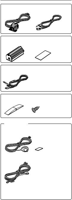
Accessories |
|
Camera (with camera bracket) |
..........1 |
Camera connection cord .......... |
1 |
Power supply box.......... |
1 |
|
Double-side adhesive tape (Large).......... |
1 |
|
Power cord .......... |
1 |
Waterproof packing .......... |
1 |
|
Camera bracket clamping screw.......... |
1 |
|
CMOS-300 only
Switch unit.......... |
1 |
|
Double-side adhesive tape (Small) .......... |
1 |
|
Head unit connection cord .......... |
1 |
The head unit connection cord is used for connection to a Kenwood car navigation system equipped etc. with the camera control function.
English | 3
Installation
 CAUTION
•The adjustments during camera setting may be hindered depending on the camera installation position. Do not install the camera securely but attach it only temporarily until the camera setting has completed.
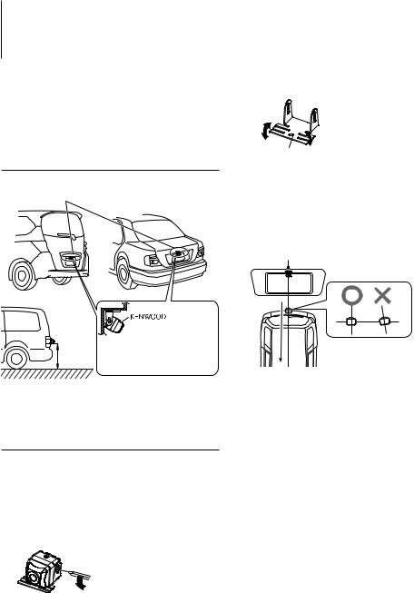
Recommended Installation Position
Examples of correct camera installation
Installation position
Mount so that the “KENWOOD” logo appears at the top.
The CMOS-300 should be installed at a height of 55 cm (21.7 inch) or more.
Installing the Camera/Adjusting its angle
1 Decide the camera installation position.
2Clean the camera installation surface.
Using a commercially available cleaner, wipe dirt, moisture and oil away from the surface on which the camera bracket is to be attached.
3 Loosen the camera bracket retaining screws.
Using a commercially available Phillips screwdriver, loosen the two retaining screws.
Perform steps 4 and 5 only when they are required.
4If required, separate the camera bracket from the camera and adjust the shape according to the surface on which it will be attached.
Bend |
Adjust the camera |
bracket shape so |
|
|
that it fits the camera |
Bend |
installation position. |
Camera bracket |
|
5Mount the camera on the camera bracket.
Mount so that the “KENWOOD” logo appears at the top.
6Fix the camera temporarily with tape, etc.
Using a piece of tape, etc., fi x the camera temporarily and adjust the angles so that the rear end of the vehicle can be viewed.
12-34
Attach the camera on the rear center position of the vehicle taking care not to hide the license plate. Make sure that the camera points straight toward the rear of the vehicle travel direction. Be careful not to lean the camera toward other directions of the vehicle, etc.
7 Complete all of the required connections.
8Display the camera video.
Some video monitors may switch automatically to the external video input function. For details, read the instruction manual for your video monitor.
9Change the shift lever to the R (Reverse) range to view the image of the rear of the vehicle.
Before viewing the camera, apply the parking brake and chock the wheels so that the vehicle will not move. Otherwise, an unexpected accident may result.
4 | CMOS-300/CMOS-200

10 Adjust the camera angle so that the rear part of the vehicle or the rear bumper is visible at the bottom of the monitor screen.
Vehicle rear part or bumper
When adjusting the camera angle, be careful not to stretch the camera cord.
11 After adjusting the camera angle, tighten the retaining screws firmly.
Inspect the retaining screws at times. If they are loose, tighten them firmly.
12 Perform the operations in “Camera Setting” (page 8). (CMOS-300 only)
If an adjustment is not possible in the currently available range, change the camera position before retrying.
13 Fix the camera firmly in position.
Peel o the paper liner from the double-side adhesive tape on the camera bracket and attach it. After attaching, push the camera bracket with your finger to ensure close adhesion.
Do not touch the adhesive surface with your hand or peel and reattach an attached tape, as these will degrade the adhesive force and may cause the camera bracket to be detached. If required, secure the bracket on the vehicle body using the camera bracket clamping screw.
Camera bracket clamping screw
Installing the Power Supply Box
1Attach double-side adhesive tape on the power supply box and then attach it under the carpet on the front passenger seat side.
Do not attach the power supply box in the following place.
-Place moistened by water.
-Unstable surface.
-Place that comes in the way of driving.
-Under high temperature.
Installing the Switch Unit (CMOS-300 only)
1Clean the switch unit installation surface.
Using a commercially available cleaner, wipe dirt, moisture and oil away from the surface on which the switch unit is to be attached.
2Attach double-side adhesive tape on the bottom of the switch unit and then attach it in an easy-to-operate position, for example near the dashboard on the driver seat side.
English | 5
 Loading...