


 Loading...
MONITOR WITH DVD RECEIVER
DDX5022/5022Y/5032
/5032M/512/52RY
DNX5120/512EX/5220/5220BT
SERVICE MANUAL
© 2008-2 PRINTED IN JAPAN B53-0620-10 (N) 519
Illustrations is DNX5220BT
Panel assy (A64-4530-11): DDX512
(A64-4532-11): DDX5022/5022Y
(A64-4535-11): DNX5120
(A64-4536-11): DNX5220BT
(A64-4537-11): DNX5220
(A64-4539-01): DDX5032/5032M
(A64-4540-01): DDX52RY
(A64-4551-01): DNX512EX
Microphone * (W01-1718-05)
Except K,R type |
Only DNX |
Only DNX5220BT |
|
Remote controller * |
Escutcheon |
Mounting hardware assy |
Lever |
(A70-2083-15) |
(B07-3165-02) |
(J22-0657-03) |
(D10-4589-04) x2 |
Size AAA battery |
|
|
|
Not supplied |
|
|
|
RC-DV340 |
|
|
|
DC cord * |
DC cord * |
Adhesive double- |
Escutcheon * |
(E30-6796-05) |
(E30-6795-05) |
coated tape * |
(B07-3172-12) |
|
|
(H30-0595-04) |
|
Cord with plug * |
Antenna module(GPS-ANT) |
Mounting hardware * |
Screw set * |
(E30-6785-05) |
(W02-5305-05) |
(J21-9867-04) |
(N99-1779-15) |
The IC3, and IC11 in the DVD unit (X37-1100-03) are not replaceable components.
When these ICs are defective, replace the whole DVD mechanism assembly (X92-6160-00). You cannot replace only the board.
* Depends on the models. Refer to the parts list.
This product uses Lead Free solder.
This product complies with the RoHS directive for the European market.
DDX5022/5022Y/5032/5032M/512/52RY
DNX5120/512EX/5220/5220BT
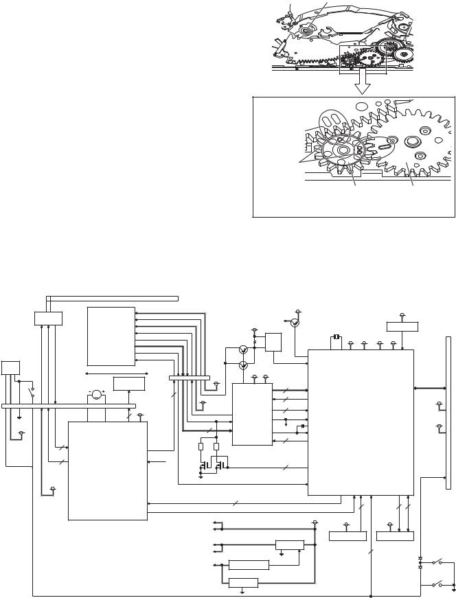
GEAR POSITION IN A DVD MECHANISM
In assembling the Traverse UD arm, Drive cam assembly, Drive gear 5 and Drive gear 4C, align register marks on these components.
Traverse UD arm
Drive cam assembly
Inscriptions (register marks) on gears
Align 6 marks as shown in the figure
Drive gear 5 Drive gear 4C Do not forcibly press gears to engage their teeth
but freely let the gears fall under their own weight and engage their teeth.
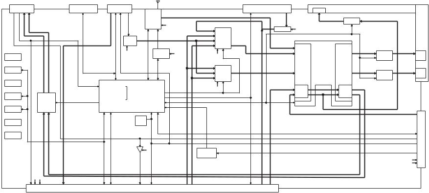
BLOCK DIAGRAM
DVS-8000V BLOCK DIAGRAM (X37-1100)
DISC
HALL
IC
|
LIM-SW |
EJEND |
D3.3V |
SW |
|
SPINDLE MOTOR
HALL BIAS |
U,V,W COIL |
HALL SENSOR |
3
3
P5V
|
|
|
PDIC VCC |
|
|
|
|
A3.3V |
|
|
|
|
|
D3.3V |
|
|
|
|
|
|
|
|
|
|
|
|
|
|
|
|
|||
|
|
|
DVD LD/CD LD |
|
|
HFM3.3V |
|
|
|
|
|
|
|
|
|
|
|
|
|
HFM |
|
|
|
|
|
|
|
|
|
|
|
||
|
|
|
|
|
A5V |
|
|
|
|
|
|
|
RESET IC |
CN2 |
||
|
|
|
|
|
|
IC12 |
|
|
|
|
|
|
||||
|
|
|
VREFH |
|
|
|
|
16.897849MHz |
|
|
||||||
|
|
|
|
|
|
|
|
|
|
|
50PIN |
|||||
OPTICAL PICKUP |
IMON/VR DVD/VR CD |
|
|
|
|
|
|
|
|
|
||||||
|
|
Q7,8 |
IOP |
|
|
|
D5V |
A3.3V |
D3.3V 1.5V |
|
|
|||||
|
|
|
PDIC I/V OUT |
|
|
|
|
|
|
|
|
|
|
|
||
|
|
|
|
|
|
DET |
|
IC4 |
|
|
|
|
|
|
|
|
|
|
|
THERMISTER |
|
|
|
|
|
|
|
|
|
|
|
|
|
|
|
|
|
|
APC |
|
|
|
|
|
|
|
|
NRST |
|
|
|
|
|
FO+/-,TR+/- |
|
|
|
|
HFM |
|
|
|
|
|
|
||
|
|
|
|
|
Tr |
|
|
|
|
|
|
|
|
|||
|
|
|
|
|
|
|
|
|
IOP(AD) |
|
|
|
|
|
|
|
|
|
|
CN1 |
|
|
A5V |
A3.3V |
|
|
|
OPTICAL DISC |
|
|
|||
|
|
|
|
A5V |
IC1 |
|
|
|
|
|
||||||
LO/EJ |
2 PHASE |
30PIN |
|
|
|
|
|
CONTROLLER |
|
|
||||||
|
|
|
|
|
|
|
ATAPI IF |
|||||||||
DC MOTOR |
STEPPING |
|
|
FRONT-END |
|
2 |
ARF,NARF |
|
|
|
|
|
||||
M |
|
|
4 |
|
|
|
3 |
|
|
|
|
|
|
|||
|
|
|
|
|
PROCESSOR |
FBAL,JLINE, |
|
|
|
|
|
D5V |
||||
|
|
|
|
|
|
|
|
|
|
|
||||||
|
|
CN3 |
HFM3.3V |
|
|
|
TSTSG |
|
|
|
|
|
|
|||
|
|
|
|
7 |
|
|
|
|
|
|
to |
|||||
|
|
28PIN |
|
|
|
|
FE,AS,RFENV,RFDIFO |
|
|
|
|
|||||
|
|
4 |
P5V |
|
|
VREFH |
|
|
OFTR,BDO,VREF2 |
|
|
|
|
MAIN |
||
IC10 |
|
|
|
|
|
|
|
|
|
UNIT |
||||||
|
|
|
|
|
|
VHALF(1.65V) |
|
|
|
|
|
|||||
|
|
|
|
|
LPC1,2 |
|
|
|
|
|
|
|
P5V |
|||
FO6,RO6 |
|
FO4,RO4 FO5,RO5 |
|
|
|
|
|
SEN,SCK,STDI |
|
|
|
|
||||
|
|
|
|
SEN,SCK,STDI |
|
|
|
|
|
|
||||||
|
|
|
|
9 |
|
A,B,C,D,E,F, |
VHALF |
TE |
|
|
|
|
|
|
|
|
|
|
|
|
|
|
RF,FE1,FE2 |
|
3 |
|
|
|
|
|
|
|
|
|
|
|
|
|
|
|
|
|
|
|
|
|
|
|
|
|
H1H,H1L,HB |
|
FO2,RO2 |
VR |
|
|
|
|
|
|
DRV.MUTE,LO.MTE, A,STEPBMS,STEPB FG,EXCNT1 |
|
|
|
|
|
|
|
|
FO3,RO3 |
|
|
|
|
|
|
SPDRV,FODRV, TRDRV,PWM8, |
SDA,SCL |
SW |
17,-FADR0 |
NCE,NWE,NOE 7-FTD0 |
|
||
|
|
|
VHALF |
|
|
|
|
|
|
|
||||||
A1,A2,A3 MOTOR & |
VREF,EC |
|
|
|
|
2 |
DVDON/ |
|
|
|
|
|
|
|
||
ACTUATOR |
|
|
|
Q1,2 |
|
|
CDON |
|
|
|
|
|
|
|
||
DRIVER |
|
|
|
|
|
|
|
|
|
|
|
|
|
DISC DET |
||
|
|
|
|
|
|
|
|
|
TEMP |
|
|
|
|
|
|
|
|
|
|
|
|
|
|
|
|
DET(AD) |
|
|
|
|
|
|
|
STBY,SPIN,IN2-6 |
|
|
9 |
|
|
|
|
|
2 |
|
21 |
8 |
|
|||
|
|
BMS,MUTE |
|
|
|
|
|
|
|
|
|
|
||||
|
|
|
FG |
|
|
|
|
|
|
|
|
|
|
|
|
|
|
|
|
|
A5V |
|
|
|
|
D5V |
|
D3.3V |
|
|
D3.3V |
|
|
|
|
|
|
|
|
|
|
|
|
|
|
|
|
|||
|
|
|
|
|
|
|
|
|
IC11 |
|
|
IC3 |
|
|
||
|
|
|
|
D5V |
|
|
|
|
|
|
|
|
|
|||
|
|
|
|
|
|
|
IC7 |
|
EEPROM |
|
FLASH ROM |
|
||||
|
|
|
|
A3.3V |
|
|
3.3V REG |
|
|
|
|
4 |
|
|
|
|
|
|
|
|
D3.3V |
|
|
|
|
|
|
|
|
|
|
SW LOST |
|
|
|
|
|
|
IC8 |
|
|
|
|
|
|
|
|
|
||
|
|
|
|
|
|
|
|
|
|
|
|
|
|
|
||
|
|
|
|
|
|
ON/OFF |
|
|
|
|
|
|
D7 |
|
||
|
|
|
|
1.5V |
|
VOLTAGE DET |
|
|
|
|
|
|
|
|||
|
|
|
|
|
|
|
|
|
|
|
|
|
|
|
||
|
|
|
|
|
|
IC9 |
|
|
|
|
|
|
|
|
|
SW LOEND |
|
|
|
|
|
|
|
|
|
|
|
|
|
|
|
|
|
|
|
|
|
|
|
1.5V REG |
|
|
|
|
|
|
|
|
|
|
2
|
(X34-575) |
|
|
|
|
|
|
|
|
|
|
|
|
ANT |
|
|
|
|
|
|
|
|
|
|
|
|
|
|
|
|
|
|
|
|
J1 |
|
|
|
|
|
|
J400 |
|
|
|
|
|
|
|
|
|
J401 |
|
|
J700 |
|
|
|
|
|
|
|
|
||||
|
|
|
|
|
|
|
|
|
|
A500 |
|
|
|
|
|
|
|
|
|
|
|
|
|
|
|
|
|||||||
|
DC CN |
|
|
|
|
RE-WRITE CN |
TV I/F JACK |
|
|
|
|
|
|
|
SIRIUS/XM KAB IF JACK |
|
|
|
JACK |
|
JACK |
|
|
||||||||||
|
|
|
|
|
|
|
|
|
|
|
|
|
|
A-OUT |
|
|
|
|
|
||||||||||||||
|
|
|
|
|
|
|
|
|
|
|
|
|
|
|
|
|
|
|
|
|
|
|
|
|
|
|
|
|
|
|
|
|
|
|
|
|
|
|
|
|
|
|
|
|
|
|
|
F/E |
|
|
|
TUN L/R |
|
|
|
|
|
|
A-OUT L/R |
|
|
|
|
|
|
|
|
|
|
|
|
|
|
|
(COMMON |
|
|
|
|
|
|
|
|
|
|
|
|
|
|
|
SAT L/R |
MUTE |
|
|
|
|
|
|
|||
|
|
|
|
DETBU DETACC PARKING REVERSE ILLUMI CONP CONANT MUTELINE |
TV SERIAL) |
|
|
|
|
|
|
|
|
|
|
|
|
|
|
|
|
|
|
|
|
|
|
|
|||||
|
|
|
|
|
|
|
|
|
|
|
TUN8V |
|
|
IC303 |
SIR PON |
|
|
IC401 |
|
|
|
|
|
|
|
|
|
||||||
|
REMOW |
|
|
FLASH MDATA |
RSTTV |
|
AMP |
|
|
A-IN L/R |
|
|
|
|
|
|
|
|
|
|
|
||||||||||||
|
|
|
FLASH SDATA |
|
|
|
|
|
MAIN |
SIR RST |
|
|
A8V |
EVOL MUTEB |
|
|
|
|
|
|
|
||||||||||||
|
|
|
|
|
|
|
FLASH CLK |
|
|
|
|
IC400 |
|
|
|
|
i-POD L/R |
AUDIO |
SAT RX |
|
|
|
|
|
|
|
|
|
|
|
|
||
|
|
|
|
|
|
|
|
|
|
|
|
|
|
|
|
|
|
|
SAT TX |
|
|
IC302 |
|
|
|
|
|
|
|
|
|
||
|
|
|
|
|
|
|
|
|
|
|
ISO |
|
|
|
|
|
TV L/R |
SEL1 |
SAT CON |
|
|
|
|
|
|
|
|
|
|
|
|||
|
Q5 |
|
|
|
|
|
TV MC REQ |
A8V |
TUN SDA |
|
RDS |
SW5V |
|
|
|
ASEL1 1 |
|
|
|
E-VOL |
|
|
|
|
PRE |
|
BLOCK |
|
|||||
|
BU3.3V |
|
FOUT-SP |
ROUT-SP |
|
|
TV SC CON |
TUN SCL |
|
|
|
A8V |
|
|
|
|
|
MUTESW |
MUTE |
|
|
||||||||||||
|
|
|
|
|
WRT E2P |
|
|
|
AM+B |
|
|
|
|
ASEL1 2 |
|
|
|
|
|
|
FR |
|
|
||||||||||
|
BU5V |
|
|
|
|
|
TV JUDGE |
|
|
|
|
|
|
|
|
|
INPUT |
|
OUT |
|
PRE |
|
|
|
|||||||||
|
Q12 |
|
|
|
|
|
TV SC REQ |
|
|
TUN SMET |
|
|
|
|
|
IC304 |
|
|
|
|
|
|
|
|
|
|
|||||||
|
|
|
|
|
|
TV SC DATA |
|
|
|
TUN IFC |
|
R QUAL |
|
|
|
|
|
|
SEL |
|
SEL |
|
MUTEF |
|
|
|
|
|
|||||
|
SW5V |
|
|
|
|
|
TV MC DATA |
|
|
|
R NOISE |
|
R DATA |
|
|
|
AUDIO |
|
|
|
|
|
|
|
|
|
|
|
|
|
|||
|
|
|
|
|
|
TV BP CLK |
|
|
|
R AFS H |
|
R CLK |
|
|
|
|
|
|
|
|
|
|
|
|
PRE |
|
|
|
|||||
|
|
|
|
|
|
|
|
|
|
|
|
|
|
|
|
|
|
|
SEL2 |
|
|
|
|
|
|
|
|
MUTE |
|
|
|
||
|
|
|
|
|
|
|
|
|
|
|
|
|
|
|
|
|
|
BE/USB L/R |
|
|
|
|
|
|
|
|
R/SW |
|
|
|
|||
|
IC2 |
|
|
|
|
|
IC104 |
|
|
|
|
|
|
|
|
|
SUB |
|
|
|
|
|
|
|
|
|
|
|
|
||||
|
|
|
|
|
|
|
|
|
|
|
|
|
|
|
|
|
|
|
|
|
|
|
|
PRE |
|
|
|
|
|
||||
|
|
|
|
|
|
|
|
|
|
|
|
|
|
|
|
|
|
|
|
|
|
|
|
|
|
|
|
|
|
|
|
|
|
|
Q22 |
IC600 |
|
|
|
|
E2P SDA |
|
(COMMON |
|
|
|
|
|
A8V |
ASEL2 1 |
|
|
ISO |
|
SP |
|
|
|
|
|
DIAGRAM |
|
|||||
|
|
|
|
PWIC STBY |
E2P SCL |
|
|
RSTTV |
|
|
DETVSYNC |
|
ASEL2 2 |
|
|
|
|
|
REMO |
|
|
|
|||||||||||
|
ILL+B |
|
FOUT-SP |
|
|
|
|
BE STBY |
|
EVOL) |
|
|
|
|
|
MUTEBEVOL MUTECEVOL MUTESWPRE MUTEFPRE |
|
|
|
|
|
|
|
|
|
|
|||||||
|
SW3.3V |
|
POWER |
|
|
PWIC MUTE |
ROM E2P SCL |
|
|
|
|
|
|
|
|
|
|
|
|
|
|
|
|
|
|
|
|
|
|
|
|
||
|
Q1 |
|
IC |
|
|
|
BEEP |
TYPE0 |
|
|
|
SYSTEM |
|
|
|
|
|
|
|
|
|
|
|
|
|
|
|
|
|
|
|
||
3 |
RSTACC PON PARKUNG |
A8V |
BU5V |
SP-OUT R |
COMPTV |
|
|
TYPE2 |
|
|
|
|
|
|
|
L/RPOD-i |
L/RBE/USB |
|
EVOLSDA EVOLSCL DCDETPWIC MUTE0EVOL MUTE1EVOL MUTE2EVOL |
|
L/RBT |
L/RNAVI |
HSY VD PWM INV PWM INV SW BL ENA VMUTE SRC KEY4 VOL+ VOLEJECT KEY ILL KEY ILLR1 KEY ILLG1 KEY ILLB1 SI X0 Y0 X1 XDATA YDATA VCOM NT PAL |
ROUT-SP |
FOUT-SP |
|
CN800 |
-(X35to) CN3 |
DNX5120/512EX/5220/5220BT |
DDX5022/5022Y/5032/5032M/512/52RY |
|||
|
A8V |
|
|
|
|
|
|
|
|
|
|
|
|
|
|
|
|
|
|
|
|
|
|
|
|
|
|
|
A-IN L/R |
|
|
|
|
|
Q502 |
|
|
|
|
|
|
|
|
|
|
|
RST |
|
|
|
|
|
|
|
|
|
|
|
|
|
|
|
|
|
|
|
|
|
TUN8V |
|
|
|
|
|
|
|
DISCDET |
|
|
IC |
|
|
|
|
|
|
|
|
|
|
|
|
|
|
|
|
|
|
|
|
|
|
Q802 |
|
|
|
|
|
|
|
BE MDATA |
|
|
|
|
|
|
|
|
|
|
|
|
|
|
|
|
|
|
|
|
|
|
||
|
|
|
|
|
|
|
|
BE SDATA |
|
|
|
|
|
|
|
|
|
|
|
|
|
|
|
|
|
|
|
|
|
|
|||
|
|
|
|
|
|
|
|
|
BE CLK |
|
|
|
|
|
|
|
|
|
|
|
|
|
|
|
|
|
|
|
|
|
|
|
|
|
|
|
|
|
|
|
NAVI RX |
|
DISCDET |
|
|
|
|
|
|
|
|
|
|
|
|
|
|
|
|
|
|
KEY RESET |
|
|
|
|
|
|
|
|
|
|
|
|
|
BE SREQ |
|
|
|
SW5V |
|
|
|
|
|
|
|
|
|
|
|
|
|
|
|
|
|
|
|
||
|
|
|
|
|
|
|
NAVI TX |
|
BE MREQ |
|
|
|
|
|
VSYNC- |
|
|
|
|
|
|
|
|
|
|
F VIN |
|
|
|
|
|||
|
|
|
|
|
|
|
PON |
BE CON |
|
|
|
|
|
|
|
|
|
|
|
|
|
|
|
|
|
|
|
|
|
||||
|
|
|
|
|
|
|
PGOOD |
|
BE INI |
|
|
|
REMOMIX |
RSTBE |
|
|
|
DET |
|
|
SAT CON |
|
|
|
|
|
|
|
|
|
|
|
|
|
|
|
|
|
|
|
P START |
|
BE RESERVE3 |
|
|
|
|
|
|
|
|
|
|
|
|
|
|
|
|
|
|
||||||
|
|
|
|
|
|
|
|
BE BUDET |
|
|
|
|
|
|
|
|
|
SIR RST |
|
|
|
|
|
|
|
TP5V |
|
|
|
|
|||
|
|
|
|
|
|
|
P PWM |
BE RESERVE1 |
|
|
|
|
|
|
|
|
SAT RX |
|
|
|
|
|
|
|
ILL+B |
|
|
|
|
||||
|
|
|
|
|
|
|
|
|
BE RESERVE2 |
|
|
|
|
|
|
|
|
|
|
|
|
|
|
|
|
|
|
|
|||||
|
|
|
|
|
|
|
|
|
|
|
|
|
|
|
|
|
SAT TX |
|
|
|
|
|
|
|
|
|
|
|
|
||||
|
|
|
|
|
|
|
|
|
|
|
|
|
|
|
|
|
|
|
|
|
|
|
|
|
|
|
|
|
|
|
|
|
|
|
|
|
|
|
|
|
|
|
|
|
|
|
|
CN801 |
|
|
|
|
|
|
|
|
|
|
|
|
|
|
|
|
|
|
|
|
|
|
|
|
|
|
|
|
|
|
|
|
to (X15- ) CN301 |
|
|
|
|
|
|
|
|
|
|
|
|
|
|
|
|
|
|
||
4
|
|
(X15-108) |
|
|
|
|
|
|
|
to (X34- ) CN801 |
|
|
|
|
|
|
|
|
|
|
|
|
|
|||
|
|
|
|
|
|
|
|
|
CN301 |
|
|
|
|
|
|
|
|
|
|
|
|
|
|
|||
|
CN1 |
|
|
|
|
|
|
|
|
|
|
|
|
|
|
|
|
|
|
|
|
|
|
|||
|
|
|
|
|
DETDISC |
|
|
COMPTV |
|
|
|
|
|
BE/USBL/R |
|
|
|
L/RBT |
|
|
|
|
POD - |
|
||
|
|
DCCN |
BU |
|
|
|
|
|
|
|
|
|
|
|
SIR PON |
|
|
|
|
|
|
|||||
|
|
|
|
|
|
|
|
|
|
|
|
|
|
|
|
|
SIR RST |
|
|
|
IC201 |
|
J201 |
|||
|
|
|
|
|
|
|
|
|
|
|
|
|
|
|
|
|
|
SAT RX |
|
|
i-POD L/R |
|
A8V |
JACK |
|
|
|
|
|
|
|
|
|
|
|
|
|
|
|
|
|
|
|
|
SAT CON |
|
|
|
|
|
i-POD L/R |
|
|
|
|
|
|
|
|
|
|
|
|
|
|
|
|
|
|
|
|
SAT TX |
|
|
|
|
|
|
|
|
|
J203 |
|
|
|
|
|
|
|
|
|
|
|
|
|
|
|
|
|
|
|
|
|
|
i- A |
|
|
|
|
|
|
|
|
|
|
V5V |
|
|
|
|
|
|
|
|
|
|
|
|
|
|
|
|||
|
JACK |
|
|
|
|
|
|
|
|
|
|
|
|
|
|
|
|
|
|
|
|
J202 |
||||
|
|
|
|
|
|
|
|
IC205 |
|
|
|
|
|
|
|
|
|
|
|
IC202 |
|
|||||
|
|
|
|
|
|
|
|
|
|
|
|
|
|
|
|
|
|
|
|
|
V5V |
|||||
|
BACK |
BC COMP |
|
|
|
|
|
|
|
|
|
|
|
|
|
i-POD COMP |
|
|
|
|
|
JACK |
|
|||
|
CAM IN |
|
|
|
|
|
|
|
|
|
|
|
|
|
|
SIR RST |
|
|
|
|
|
i-POD COMP |
|
|||
|
|
|
|
IC206 |
|
|
|
|
COMP |
|
|
|
|
|
|
|
|
|
|
|
|
|
POD |
|
||
|
|
|
VOUT COMP |
|
|
|
|
|
|
|
|
|
|
|
SAT TX |
|
|
|
|
|
|
|
- |
|
||
|
VOUT |
|
|
|
|
|
|
VIDEO SW |
|
|
|
|
|
|
|
|
|
|
|
|
|
i V |
|
|||
|
V5V |
|
|
|
|
|
|
|
|
|
|
|
|
|
|
|
|
|
|
|
|
|
||||
|
|
|
|
|
|
|
|
RGB SEL1 |
|
|
|
|
|
|
|
IC301 |
|
|
|
|
|
|
|
|
|
|
|
|
|
|
|
|
|
|
|
|
|
|
|
|
|
|
|
IC501 |
|
|
|
|
|
|
|
||
|
|
|
|
|
AOUTSEL |
|
|
|
|
|
|
|
|
|
|
|
3.3V |
5V |
MIX |
A8V |
|
|
|
|
|
|
|
|
|
|
|
|
|
|
|
|
COMPBE |
|
|
|
|
|
|
|
|
|
|
|
|||||
|
|
|
ONLY |
|
|
|
|
|
|
|
|
|
|
|
|
|
|
|
|
|
|
|
|
|||
|
|
|
DDX |
|
|
|
|
|
|
|
|
|
|
|
|
|
D5V |
|
|
|
|
|
|
MONI COMP |
|
|
|
JACKNAVI |
J401 |
NAVI L/R |
|
|
|
|
|
|
|
|
|
|
|
|
|
|
|
|
|
|
|
|
FRONT AUX COMP |
|
J1 |
|
NAVI SYNC |
|
|
|
IC207 |
|
|
|
|
|
|
|
|
|
|
|
|
|
|
|
|
MONI R/G/B |
|
|||
|
|
|
NAVI R/G/B |
|
|
|
|
|
|
|
|
|
|
|
|
|
|
|
|
|
|
|
|
|
||
|
|
|
|
|
|
RGB SW |
MUTE |
RGB MUTE |
|
|
|
|
|
|
|
|
|
|
|
|
|
|
||||
|
|
|
MIX REMO |
|
|
|
|
BE MDATA |
SIR RST |
|
|
|
|
|
MST SDA |
|
|
|||||||||
|
|
|
|
|
|
|
|
|
|
|
|
|
|
|
|
|
|
|
|
|||||||
|
|
|
MAPUP DET |
|
|
|
|
|
|
|
|
|
|
BE SDATA |
SAT TX |
|
|
|
|
|
MST SCL |
|
|
|||
|
to |
|
|
|
|
V5V |
|
|
|
|
|
|
BE CLK |
|
|
|
|
|
|
|
|
MST RST |
J301 |
to(X35- ) |
||
|
|
|
|
|
|
|
|
|
AOUT SEL |
|
BE STBY |
IC652, |
A8V |
|
|
|
|
|
MST WP |
|||||||
|
|
|
|
|
|
|
|
|
|
|
BE AMUTE |
|
|
|
|
|
MST WAIT |
|||||||||
|
|
|
|
ONLY |
|
|
R/G/B |
|
|
VSEL SCL |
|
|
|
|
|
|
|
|||||||||
|
|
|
|
|
|
|
|
|
|
|
|
MUTE/LPF |
|
|
|
|
|
|
||||||||
|
|
|
|
|
|
|
|
|
|
|
VSEL SDA |
|
DISKDET |
IC654 |
|
|
|
|
|
|
VMUTE |
|
|
|||
|
|
|
|
|
|
|
|
|
|
|
|
BE SREQ |
|
|
|
|
|
|
|
|
|
|
||||
|
GARMINto NAVI |
|
NAVI TX |
|
DNX |
|
|
BE |
|
|
|
|
|
BE MREQ |
|
|
|
|
|
A8V |
|
BL14V |
|
|
||
|
CN401 |
NAVI RX |
|
|
|
|
MIX REMO |
IC602 |
IC601 |
RSTBE |
BE CON |
|
IC651 |
|
|
|
|
|
V6V |
|
|
|||||
|
ACC RST |
|
|
|
|
IC701 BER/G/B |
COMPBE |
|
BE INI |
|
SDO0 |
|
|
|
|
DC/DC |
|
|
|
|||||||
|
|
|
PARKING |
|
|
|
|
|
|
VIDEO DRV |
VIDEO DRV |
|
BE BUDET |
2ch DAC |
|
|
|
|
|
D5V |
|
|
||||
|
|
|
|
|
|
|
|
|
|
|
|
|
|
BE RESERVE1 |
|
|
|
|
PON |
A5V |
|
D3.3V |
|
|
||
|
|
|
BU5V |
|
|
|
|
|
|
|
|
|
|
BE RESERVE2 |
SCLK |
|
|
|
P PWM |
|
|
|
|
|||
|
|
|
D5V |
|
|
|
IC804 |
|
|
V5V |
V5V |
|
|
BE RESERVE3 |
LRCLK |
A5V |
|
|
PGOOD |
IC101 |
|
|
|
|
||
|
|
|
|
|
|
|
|
|
|
|
|
|
|
|
|
MCLK |
|
|
|
P START |
|
|
|
|
|
|
|
|
|
|
|
USB5V |
OVER CURRENT |
MAPUP DET |
|
|
|
|
|
|
|
|
|
|
|
|
|
|
|
|
|||
|
|
|
|
|
PROTECTION |
|
|
|
|
|
|
|
|
|
|
|
|
|
|
|
|
|
||||
|
|
|
|
|
|
|
|
|
|
|
|
|
|
|
|
|
|
|
|
|
|
|
|
|
|
|
|
|
|
|
|
DP |
IC801 |
|
USB RST |
|
|
|
|
|
|
|
|
|
|
|
V6V |
D5V |
|
|
|||
|
|
|
|
|
|
|
|
|
|
|
|
|
|
|
|
|
|
|
|
|
|
|
|
|
||
|
W801 |
|
|
DM |
|
|
|
ATAPI(DATA) |
|
|
B/E |
|
|
|
|
|
|
|
|
|
|
|
|
|||
|
|
|
DP |
|
USB H/C |
|
|
|
|
|
|
|
D3.3V |
V5V |
|
|
|
|
||||||||
|
|
|
|
|
|
|
|
|
|
|
|
|
|
|
|
|
|
|
|
|
||||||
|
USB CABLE |
|
|
DM |
|
|
ADDRESS |
|
|
DATA |
ADDRESS |
|
|
|
|
|
|
|
|
|
|
|
|
|
|
|
|
IF |
|
|
|
|
|
|
|
|
|
|
|
|
|
|
|
|
|
|
|
IC102 |
|
|
|
|
|
|
|
|
USB5V |
|
|
|
|
|
|
|
|
|
|
|
|
|
|
|
D1.8V |
|
|
|
|
|
||
|
|
|
|
|
|
|
|
|
|
|
|
|
|
|
|
|
|
|
|
|
DC/DC |
|
|
|
||
|
|
|
|
|
|
|
USB3.3V USB1.8V |
|
|
X701 |
|
|
CP RDY |
SPI DO |
|
BT RST |
|
|
|
|
|
|
||||
|
|
|
|
|
|
|
|
|
|
|
|
|
|
|
|
|
|
|
|
|||||||
|
|
|
|
|
|
|
|
|
|
X'TAL |
|
|
CP RST |
SPI DI |
|
BT RX |
|
|
|
|
|
|
|
|
||
|
|
|
|
|
|
|
D3.3V |
|
|
|
|
|
|
SPI CLK |
|
BT TX |
|
|
|
|
|
|
|
|
||
|
|
|
|
|
|
|
|
|
27MHz |
|
|
|
|
|
|
|
D3.3V |
|
USB5V/P5V |
|
|
|||||
|
|
|
|
|
|
|
|
|
|
|
IC851 |
SPI RDY |
|
|
|
|
|
|
|
|||||||
|
|
|
|
|
X801 |
IC853 |
|
|
|
|
|
|
|
|
|
|
|
|
||||||||
|
|
|
|
|
|
|
|
|
|
i-Pod |
|
|
D3.3V |
|
|
BT L/R |
|
|
|
|
|
|
||||
DVS8020V |
MECHADVD |
CN701 |
P5V |
|
USB5V |
|
|
|
|
IC703, |
|
|
|
A501 |
|
BT MIC IN |
|
|
|
|
|
|||||
|
|
|
|
|
|
32.468kHz |
D3.3V |
SPDIFO |
|
|
|
|
|
|
||||||||||||
|
|
|
|
|
X'TAL |
|
|
|
|
|
AUTHENTI- |
|
|
ONLY |
|
|
D1.8V |
USB1.8V |
USB3.3V |
|
|
|||||
|
|
|
|
|
24MHz |
|
|
IC702 |
IC704 |
|
CATION |
|
|
|
|
|
|
|
||||||||
|
|
|
ATAPI |
|
|
|
|
|
|
FLASH 64Mb |
SDRAM |
X851 |
|
|
|
|
DNX |
|
|
|
|
|
|
|
|
|
|
|
|
RESET |
|
|
|
|
|
|
|
|
|
|
|
D3.3V |
|
|
|
|
|
|
|
||||
|
|
|
|
|
|
|
|
|
|
|
128Mb*2 |
|
X'TAL |
|
|
|
|
|
|
|
|
|
|
|
|
|
|
to |
|
D5V |
|
|
|
|
|
|
D3.3V |
D3.3V |
|
|
|
|
|
|
to BT |
|
|
|
|
|
|
|
|
|
|
|
|
|
|
FAN CN |
|
|
|
|
|
|
SPD JACK |
MODULE |
|
MIC JACK |
|
|
|
|
||||||
|
|
|
|
|
|
|
|
|
|
|
|
|
|
|
|
|
|
|
|
|||||||
|
|
|
|
|
CN2 |
|
|
|
|
|
|
|
|
J681 |
|
|
|
|
J501 |
|
|
|
|
|
||
DNX5120/512EX/5220/5220BT |
DDX5022/5022Y/5032/5032M/512/52RY |
BLOCK |
|
DIAGRAM |
|

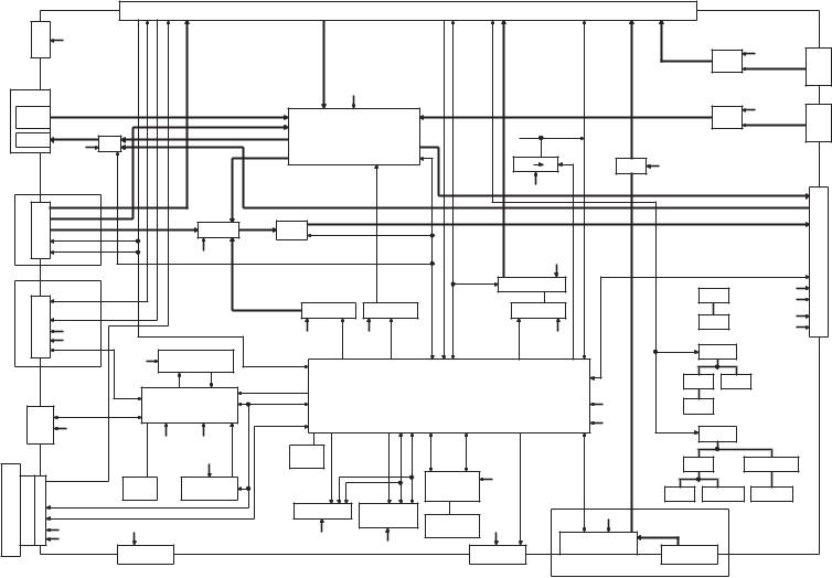
DDX5022/5022Y/5032/5032M/512/52RY
DNX5120/512EX/5220/5220BT
BLOCK DIAGRAM
(X35-489) |
to (X34- ) CN800 |
|
CN3 |
||
|
||
|
|
(X15- ) J301 |
J1 |
to |
|
|
|
D5V
DCDC
-12V |
12.5V |
15V |
-10V |
|
|
D3.3V |
V6V |
|
SW2.5V |
SW5.3V |
V5V |
MONI COMP
MONI R/G/B
INV PWM
ENABLE
PWM
INV SW
IC1
INVERTER |
BL 14V |
|
CIRCUIT |
||
|
TP5V
CN1
MST SDA
MST SCL
MST RST
MST WP
MST WAIT
VMUTE
IC203
Y0
X0
X1
XDATA
YDATA
CN5
HSY |
VCOM |
|
|
|
J2 |
|
|
|
|
|
|
||
VD |
|
|
|
F AUX |
||
NT PAL |
|
|
|
|
||
|
|
|
|
|
MINI |
|
|
|
|
|
|
JACK |
|
|
|
|
A-IN L/R |
|
A-IN |
|
|
|
|
|
|
|
|
|
|
|
F VIN |
|
V-IN |
|
|
|
|
|
|
|
|
|
|
|
VOL+ |
|
|
|
|
|
|
VOL- |
|
VOL |
|
|
|
|
|
|
|
|
|
|
|
REMO |
D5V |
|
REMO |
|
|
|
|
|
|
|
|
|
|
SRC |
|
|
|
|
|
|
KEY4 |
|
|
|
|
|
|
VOL+ |
|
|
|
|
|
|
VOL- |
|
|
|
|
|
|
EJECT |
|
20PIN |
SW |
|
|
|
|
|
||
|
|
|
SI |
|
FFC |
|
|
|
|
|
CN7/CN6 |
SI |
|
|
|
|
KEY ILL |
|
||
|
|
|
ILL+B |
|
|
|
|
|
|
KEY ILLR1 |
|
|
|
|
|
|
KEY ILLG1 |
|
|
|
|
|
|
KEY ILLB1 |
|
LED |
|
|
|
|
|
|
|
|
TIMING |
|
|
IC201 |
|
|
|
CONTROLLER |
|
|
|
|
|
|
|
VCOM |
VCOM |
12.5V |
|
|
|
|
|
AMP |
-12V |
|
|
|
SW2.5V V5V |
V5V -10V |
15V SW5.3V |
|
|
|
|
|
CN4 |
|
|
|
|
|
BACK LIGHT |
TOUCH PANEL |
LCD PANEL |
5
DDX5022/5022Y/5032/5032M/512/52RY
DNX5120/512EX/5220/5220BT
COMPONENTS DESCRIPTION
● VIDEO CONTROL UNIT (X15-108x-xx)
Ref. No. |
Application / Function |
Operation / Condition / Compatibility |
|
|
|
|
|
IC100 |
DC/DC converter IC |
DC/DC control for USB5V/D5V |
|
|
|
|
|
IC101 |
DC/DC converter IC |
DC/DC control for SW3.3V/V6V |
|
|
|
|
|
IC201 |
AUDIO ISO AMP |
iPod audio signal |
|
|
|
|
|
IC202 |
VIDEO ISO AMP |
iPod video signal |
|
|
|
|
|
IC203 |
Regulator |
V6V→V5V regulator |
|
|
|
|
|
IC205 |
Video selector |
5IN 2OUT DVD-BE/NAVI/TV/Ipod/BackCamera COMPOSITE signal Select |
|
|
|
|
|
IC206 |
Video selector |
Selector for selecting FRONT AUX output or IC205 output for external video output |
|
|
|
|
|
IC207 |
Video selector |
DVD-BE and NAVI RGB selector |
|
|
|
|
|
IC301 |
AND x 4 |
KAB IF 3.3V→5V LEVEL SHIFT |
|
|
|
|
|
IC501 |
OP-AMP X 2 |
LPF for BT-AUDIO |
|
|
|
|
|
IC502 |
BUS BUFFER X 2 |
BUFFER for BT control signal wave shaping |
|
|
|
|
|
IC601 |
Video amplifier |
DVD-BE COMPOSITE SIGNAL LPF/BUFFER |
|
|
|
|
|
IC602 |
Video amplifier |
DVD-BE RGB SIGNAL LPF/BUFFER |
|
|
|
|
|
IC651 |
AUDIO DAC |
DVD-BE AUDIO D/A CONVERTER |
|
|
|
|
|
IC652 |
OP-AMP X 2 |
DVD-BE AUDIO LPF |
|
|
|
|
|
IC653 |
Regulator |
Regulator for 8.4V→A5V AUDIO DAC |
|
|
|
|
|
IC654 |
OP-AMP X 2 |
For AUDIO REFERENCE4V |
|
|
|
|
|
IC691 |
INVERTER |
SPDIF OUT BUFFER |
|
|
|
|
|
IC692 |
AND |
For DVD-BE IC RESET signal |
|
|
|
|
|
IC701 |
MPEG DECODER |
DVD/USB MPEG DECODER |
|
|
|
|
|
IC702 |
64M FLASH |
FLASH MEMORY(PMP 4Z3 / MP 4Z4) for MPEG DECODER |
|
|
|
|
|
IC703,704 |
128M SDRAM |
SDRAM for MPEG DECODER |
|
|
|
|
|
IC705 |
Regulator |
3.3V→1.8V regulator for MPEG DECODER |
|
|
|
|
|
IC801 |
USB HOST CONTROLLER |
2 ports (For external and GARMIN NAVI) USB HOST CONTORLLER |
|
|
|
|
|
IC804 |
Fixed Current Limit |
Large current distribution switch for USB |
|
Power Distribution Switch |
|||
|
|
||
|
|
|
|
IC805 |
Regulator |
5V→3.3V regulator for USB |
|
|
|
|
|
IC806 |
Regulator |
SW3.3V→1.8V regulator for USB |
|
|
|
|
|
IC851 |
iPod Authentication |
iPod Authentication |
|
Coprocessor |
|||
|
|
||
|
|
|
|
IC853 |
D-TYPE LATCH X 8 |
Address latch for USB H/C |
|
|
|
|
|
Q1~3 |
SW |
P-ON 14V control |
|
|
|
|
|
Q4 |
SW FET |
P-ON 14V ON/OFF |
|
|
|
|
|
Q100~103 |
SW |
DC/DC protection control |
|
|
|
|
|
Q104 |
SW |
DC/DC SW FET (USB5V) |
|
|
|
|
|
Q105 |
SW |
DC/DC SW FET (D5V) |
|
|
|
|
|
Q106 |
SW |
DC/DC SW FET (SW3.3V) |
|
|
|
|
6
DDX5022/5022Y/5032/5032M/512/52RY
DNX5120/512EX/5220/5220BT
COMPONENTS DESCRIPTION
Ref. No. |
Application / Function |
Operation / Condition / Compatibility |
|
|
|
Q107 |
SW |
DC/DC SW FET (V6V) |
|
|
|
Q202 |
BUFFER |
RGB signal R |
|
|
|
Q203 |
BUFFER |
RGB signal G |
|
|
|
Q204 |
BUFFER |
RGB signal B |
|
|
|
Q205 |
SW |
RGB signal MUTE R |
|
|
|
Q206 |
SW |
RGB signal MUTE G |
|
|
|
Q207 |
SW |
RGB signal MUTE B |
|
|
|
Q301,302 |
SW |
KAB_RX error connection protection |
|
|
|
Q303 |
SW |
For KAB_TX control |
|
|
|
Q651 |
SW |
DVD AUDIO MUTE L-CH |
|
|
|
Q652 |
SW |
DVD AUDIO MUTE R-CH |
|
|
|
Q653,654 |
SW |
DVD AUDIO MUTE control |
|
|
|
Q681 |
BUFFER |
SPDIF OUTPUT BUFFER |
|
|
|
● ELECTRIC UNIT (X34-575x-xx)
Ref. No. |
Application / Function |
Operation / Condition / Compatibility |
|
|
|
IC1 |
3-terminal regulator |
For Audio8V |
|
|
|
IC2 |
3.3V regulator |
BU_3.3V |
|
|
|
IC100 |
Buffer for remote controller |
Remote controller signal waveform shaping |
|
|
|
IC101 |
Voltage detector |
μ-com reset voltage (3.5V) monitoring |
|
|
|
IC103 |
E2PROM |
For saving the settings |
|
|
|
IC104 |
System μ-com IC |
System control |
|
|
|
IC105 |
|
NAVI interface waveform conversion (3.3 → 5V) |
|
|
|
IC302 |
Electronic volume IC |
Audio volume control and audio signal selection |
|
|
|
IC303 |
Logic IC (multiplexer) |
Audio signal selection (Main) |
|
|
|
IC304 |
Logic IC (multiplexer) |
Audio signal selection (Sub) |
|
|
|
IC400 |
AUDIO ISO AMP |
For TVBOX audio signal |
|
|
|
IC401 |
AUDIO ISO AMP |
For KAB audio signal |
|
|
|
IC402 |
Logic IC (inverter) |
TVBOX data signal waveform shaping |
|
|
|
IC500 |
RDS decoder IC |
For RDS signal processing and demodulation |
|
|
|
IC600 |
Power IC |
Power amplifier for speaker output |
|
|
|
Q1,2 |
Transistor |
Audio8V |
|
|
|
Q3,4 |
Transistor |
P_CON output circuit |
|
|
|
Q5 |
Transistor |
BU5V |
|
|
|
Q6 |
Transistor |
Reverse detection circuit |
|
|
|
Q7 |
Transistor |
Audio8V |
|
|
|
Q8 |
Transistor |
BU5V |
|
|
|
7
DDX5022/5022Y/5032/5032M/512/52RY
DNX5120/512EX/5220/5220BT
COMPONENTS DESCRIPTION
Ref. No. |
Application / Function |
Operation / Condition / Compatibility |
|
|
|
Q9 |
Transistor |
P_CON output circuit |
|
|
|
Q10 |
Transistor |
Parking detection circuit |
|
|
|
Q11 |
Transistor |
P_CON output circuit |
|
|
|
Q12 |
Transistor |
SW5V circuit |
|
|
|
Q13 |
Transistor |
ILLUMI detection circuit |
|
|
|
Q14 |
Transistor |
ANT_CON output circuit |
|
|
|
Q15 |
Transistor |
SW5V circuit |
|
|
|
Q16 |
Transistor |
ANT_CON output circuit |
|
|
|
Q17 |
Transistor |
BU detection circuit |
|
|
|
Q20 |
Transistor |
Surge detection circuit |
|
|
|
Q21,22 |
Transistor |
SW3.3V circuit |
|
|
|
Q23 |
Transistor |
ACC detection circuit |
|
|
|
Q24,25 |
Transistor |
SW14V circuit |
|
|
|
Q100~102 |
Transistor |
ACC detection/KEY RESET |
|
|
|
Q103,104 |
Transistor |
DET MUTE circuit (Trigger Bu-DET) |
|
|
|
Q105 |
Transistor |
DET MUTE circuit (Trigger Reset) |
|
|
|
Q107 |
Transistor |
TVBOX RESET |
|
|
|
Q108 |
Transistor |
DET MUTE circuit (Trigger Bu-DET) |
|
|
|
Q110 |
Transistor |
SI |
|
|
|
Q111 |
Transistor |
Synchronizing separator circuit of FRONT VIDEO input |
|
|
|
Q112 |
Transistor |
SI |
|
|
|
Q113~118 |
Transistor |
Synchronizing separator circuit of FRONT VIDEO input |
|
|
|
Q300 |
Transistor |
Electronic volume IC MUTE |
|
|
|
Q301 |
Transistor |
For AUDIO selector |
|
|
|
Q303~305 |
Transistor |
For AUDIO selector |
|
|
|
Q403 |
Transistor |
KAB power supply |
|
|
|
Q406 |
FET |
KAB power supply |
|
|
|
Q407 |
Transistor |
KAB detection |
|
|
|
Q500~503 |
Transistor |
TUNER8V circuit |
|
|
|
Q504,505 |
Transistor |
On when AM (Tuner 8V) |
|
|
|
Q700 |
Transistor |
Pre-OutMute circuit (AV-OUT) |
|
|
|
Q701 |
Transistor |
Pre-OutMute circuit (REAR, SUB) |
|
|
|
Q702~705 |
Transistor |
Pre-OutMute circuit (FRONT) |
|
|
|
Q706~708 |
Transistor |
Pre-OutMute circuit (REAR, SUB) |
|
|
|
Q709~711 |
Transistor |
Pre-OutMute circuit (AV-OUT) |
|
|
|
Q800,801 |
Transistor |
LED9V SW |
|
|
|
Q802,803 |
Transistor |
LED9V |
|
|
|
8
DDX5022/5022Y/5032/5032M/512/52RY
DNX5120/512EX/5220/5220BT
COMPONENTS DESCRIPTION
Ref. No. |
Application / Function |
Operation / Condition / Compatibility |
|
|
|
Q804 |
Transistor |
X15 SW-REG PSTART |
|
|
|
● VIDEO UNIT (X35-4890-10)
Ref. No. |
Application / Function |
Operation / Condition / Compatibility |
|
|
|
IC1 |
Inverter control IC |
Control and drive of the inverter circuit for the back light |
|
|
|
IC101 |
NOT |
Reverse |
|
|
|
IC102 |
DC/DC converter IC |
+12.5V/-12.0V power supply for VCOM amplifier and +15.0V power supply for LCD |
|
|
|
IC200 |
Regulator |
2.5V regulator |
|
|
|
IC201 |
Op-amp |
For VCOM amplifier |
|
|
|
IC202 |
D flip flop |
LCD dot clock timing |
|
|
|
IC203 |
γ T/C |
Control of LCD module |
|
|
|
IC204 |
OR |
For V_MUTE |
|
|
|
IC205 |
Regulator |
5.3V regulator |
|
|
|
IC206 |
Buffer |
5V→3.3V level conversion |
|
|
|
IC207 |
FROM |
For Mstar FW |
|
|
|
IC208 |
Regulator |
5.3V regulator |
|
|
|
IC501 |
AND |
3.3V→5V level conversion |
|
|
|
IC700 |
Remote controller photoreceptor |
Detection for remote controller |
|
|
|
Q1 |
5V constant voltage |
5V power supply for inverter control IC |
|
|
|
Q2 |
Dimmer SW |
Turn on or off in response to the PWM control signal to dimmer the back light |
|
|
|
Q3 |
SW |
SW to change the free run frequency for inverter control IC |
|
|
|
Q4,5 |
Inverter Driver |
Drive of the inverter circuit |
|
|
|
Q100 |
-10V regulator |
LCD-10V regulator |
|
|
|
Q101 |
-10V regulator control |
LCD-10V regulator |
|
|
|
Q201,202 |
Buffer |
For VCOM current amplification |
|
|
|
Q400 |
Buffer |
CVBS2 |
|
|
|
Q401 |
Buffer |
CVBS1 |
|
|
|
Q450 |
SW |
SW to be turned on or off by NTSC/PAL signal and to change the filter constants |
|
|
|
Q451 |
Buffer |
For VCOM automatic adjustment |
|
|
|
Q500 |
Touch panel X0 SW |
X0 SW: Turn on in response to X axis input and apply voltage |
|
|
|
Q501 |
Touch panel Y0 SW |
Y0 SW: Turn on in response to Y axis input and apply voltage |
|
|
|
Q502 |
Touch panel X1 SW |
X1 SW: Turn on in response to detection of the panel touch or X axis input and apply voltage |
|
|
|
Q503 |
Touch panel Y0/Y1 SW |
Y0/Y1 SW: Turn on in response to Y axis input and turn off in response to X axis input |
|
|
|
Q504 |
Touch panel Y0 SW |
Y0 SW: Turn on in response to Y axis input and apply voltage |
|
|
|
Q600 |
SW |
RGB_LED SW (green) |
|
|
|
Q601 |
SW |
RGB_LED SW (red) |
|
|
|
Q602 |
Buffer |
AUX |
|
|
|
9
DDX5022/5022Y/5032/5032M/512/52RY
DNX5120/512EX/5220/5220BT
COMPONENTS DESCRIPTION
Ref. No. |
Application / Function |
Operation / Condition / Compatibility |
|
|
|
Q603 |
SW |
RGB_LED SW (blue) |
|
|
|
Q604 |
SW |
LED SW (EJECT,DISC) |
|
|
|
Q606 |
SW |
5V→3.3V level conversion |
|
|
|
● DVD UNIT (X37-1100-03)
Ref. No. |
Application / Function |
Operation / Condition / Compatibility |
|
|
|
IC1 |
RF signal processing IC |
RF signal processing |
|
|
|
IC3 |
FLASH ROM |
Maintain F/W for optical DISC control IC |
|
|
|
IC4 |
Optical disc control IC in μ-com |
Optical DISC general control / ATAPI interface |
|
|
|
IC5 |
Voltage detection IC |
For system resetting of optical DISC control IC |
|
|
|
IC7 |
3.3V power supply |
5V→3.3V |
|
|
|
IC8 |
Voltage detection IC |
For 1.5V power supply IC voltage monitor |
|
|
|
IC9 |
1.5V power supply |
5V→1.5V |
|
|
|
IC10 |
Driver IC |
Focus coil, Tracking coil, Spindle motor, Sled motor and Lo/Ej motor drive |
|
|
|
IC11 |
EEPROM |
Maintain data for optical DISC control IC |
|
|
|
IC12 |
OP-AMP for Iop measurement |
For IOP measurement |
|
|
|
Q1 |
Register integrated transistor |
SL. MUTE control |
|
|
|
Q2 |
Register integrated transistor |
For FG signal |
|
|
|
Q3 |
Register integrated transistor |
LO.MUTE control |
|
|
|
Q4 |
Register integrated transistor |
DRMU control |
|
|
|
Q5 |
MOS-FET |
Laser diode ON/OFF control for DVD |
|
|
|
Q6 |
MOS-FET |
Laser diode ON/OFF control for CD |
|
|
|
Q12 |
Transistor for APC |
Laser diode brightness control for CD |
|
|
|
Q13 |
Transistor for APC |
Laser diode brightness control for DVD |
|
|
|
Q14 |
MOS-FET |
For IOP measurement |
|
|
|
Q15 |
Register integrated transistor |
HFM ON/OFF control |
|
|
|
Q18,19 |
Register integrated transistor |
3.3V power supply IC ON timing control |
|
|
|
10
DDX5022/5022Y/5032/5032M/512/52RY
DNX5120/512EX/5220/5220BT
MICROCOMPUTER’S TERMINAL DESCRIPTION
● SYSTEM MICROCOMPUTER 30878MJBA21GP (X34-575: IC104)
Pin No. |
Pin Name |
I/O |
Application |
Processing / Operation / Description |
|
|
|
|
|
|
|
1 |
EVOL_SDA/EVOL_SDA |
I/O |
Communication data with E-VOL |
|
|
|
|
|
|
|
|
1 |
EVOL_SDA/E2P_SDA |
O |
Communication data with E2P |
|
|
|
|
|
|
|
|
2 |
TV_MC_REQ |
O |
Request to TV μ-com |
|
|
|
|
|
|
|
|
2 |
NC |
O |
Output from model without TV is fixed to “L” |
|
|
|
|
|
|
|
|
3 |
TV_SC_CON |
O |
Request to start TV μ-com |
|
|
|
|
|
|
|
|
3 |
NC |
O |
Output from model without TV is fixed to “L” |
|
|
|
|
|
|
|
|
4 |
VSYNC_DET |
I |
Video external input detection |
Detects if there is VSYNC signal or not |
|
|
|
|
|
|
|
5 |
VOL+ |
I |
Detects VOL key |
Detects pulse width |
|
15 pulses/360°, 2 clicks, 1 pulse |
|||||
|
|
|
|
||
|
|
|
|
|
|
6 |
VOL- |
I |
Detects VOL key |
Detects pulse width |
|
15 pulses/360°, 2 clicks, 2 pulse |
|||||
|
|
|
|
||
|
|
|
|
|
|
7 |
HSY |
I |
HD input |
Counts HD |
|
|
|
|
|
|
|
8 |
VD |
I |
VD (VSYNC) input |
|
|
|
|
|
|
|
|
9 |
SRC |
I |
Source key |
|
|
|
|
|
|
|
|
10 |
TV_SC_REQ |
I |
Request from TV μ-com |
|
|
|
|
|
|
|
|
10 |
NC |
O |
Output from model without TV is fixed to “L” |
|
|
|
|
|
|
|
|
11 |
REVERSE |
I |
Reverse detection |
L: Detection, H: Normal |
|
|
|
|
|
|
|
12 |
PWIC_STBY |
O |
Power IC standby |
H: ON, L: OFF |
|
|
|
|
|
|
|
13 |
INV_PWM |
O |
Inverter frequency control (Output by timer) |
|
|
|
|
|
|
|
|
14 |
PWIC_MUTE |
O |
Power IC output mute control |
H: OFF, L: ON |
|
|
|
|
|
|
|
15 |
BYTE |
|
|
|
|
|
|
|
|
|
|
16 |
CNVSS |
|
|
|
|
|
|
|
|
|
|
17 |
XCIN |
|
|
|
|
|
|
|
|
|
|
18 |
XCOUT |
|
|
|
|
|
|
|
|
|
|
19 |
RESET |
|
|
|
|
|
|
|
|
|
|
20 |
XOUT |
|
|
|
|
|
|
|
|
|
|
21 |
VSS |
|
|
|
|
|
|
|
|
|
|
22 |
XIN |
|
|
|
|
|
|
|
|
|
|
23 |
VCC1 |
|
|
|
|
|
|
|
|
|
|
24 |
NMI |
|
|
|
|
|
|
|
|
|
|
25 |
ACC_DET |
I |
ACC detection |
H: ACC reduced power detection |
|
|
|
|
|
|
|
26 |
BU_DET |
I |
Backup power supply detection |
H: Backup reduced power detection |
|
|
|
|
|
|
|
27 |
R_CLK |
I |
Clock input from RDS decoder |
|
|
|
|
|
|
|
|
27 |
NC |
O |
Output from model without RDS is fixed to “L” |
|
|
(To destination X and V) |
|
||||
|
|
|
|
||
|
|
|
|
|
|
28 |
NC |
O |
|
|
|
|
|
|
|
|
|
29,30 |
NC |
O |
|
Not used. Output is fixed to “L” |
|
|
|
|
|
|
|
31 |
PWM |
O |
LCD brightness control (PWM output) |
PWM output synchronized with VSY |
|
|
|
|
|
|
|
32 |
PARKING |
I |
Parking detection (For all the destinations) |
H: Detection, L: When car is running |
|
|
|
|
|
|
|
33 |
BEEP |
O |
BEEP |
PWM output |
|
|
|
|
|
|
|
34 |
NC |
O |
|
|
|
|
|
|
|
|
|
35 |
POWER_PWM |
O |
Frequency control of DC-DC_IC (CLK output) |
|
|
|
|
|
|
|
|
36 |
NAV_RX |
I |
Communication with navigation system |
|
|
|
|
|
|
|
|
37 |
NAVI_TX |
O |
Communication with navigation system |
|
|
|
|
|
|
|
|
38 |
TV_MC_DATA |
O |
Data output to TV μ-com |
|
|
|
|
|
|
|
11
DDX5022/5022Y/5032/5032M/512/52RY
DNX5120/512EX/5220/5220BT
MICROCOMPUTER’S TERMINAL DESCRIPTION
Pin No. |
Pin Name |
I/O |
Application |
Processing / Operation / Description |
|
|
|
|
|
|
|
38 |
NC |
O |
Output from model without TV is fixed to “L” |
|
|
|
|
|
|
|
|
39 |
VCC1 |
|
|
|
|
|
|
|
|
|
|
40 |
TV_SC_DATA |
I |
Data input from TV μ-com |
|
|
|
|
|
|
|
|
40 |
NC |
O |
Output from model without TV is fixed to “L” |
|
|
|
|
|
|
|
|
41 |
VSS |
|
|
|
|
|
|
|
|
|
|
42 |
TV_BP_CLK |
O |
Communication clock with TV μ-com |
|
|
|
|
|
|
|
|
42 |
NC |
O |
Output from model without TV is fixed to “L” |
|
|
|
|
|
|
|
|
43 |
NC |
O |
|
|
|
|
|
|
|
|
|
44 |
TUN_SDA |
I/O |
Communication data with tuner |
|
|
|
|
|
|
|
|
45 |
TUN_SCL |
O |
Communication clock with tuner |
|
|
|
|
|
|
|
|
46 |
R_DATA |
I |
“DATA” input from RDS decoder |
|
|
|
|
|
|
|
|
46 |
NC |
O |
Output from model without RDS is fixed to “L” |
|
|
|
|
|
|
|
|
47 |
R_QUAL |
I |
“QUAL” input from RDS decoder |
|
|
|
|
|
|
|
|
47 |
NC |
O |
Output from model without RDS is fixed to “L” |
|
|
|
|
|
|
|
|
48~51 |
NC |
O |
|
|
|
|
|
|
|
|
|
52 |
SI |
O |
SI control |
H: ON, L: OFF |
|
|
|
|
|
|
|
53,54 |
NC |
O |
|
|
|
|
|
|
|
|
|
55 |
TYPE3 |
I |
Terminal for destination (BT is required or not) |
H: With BT, L: Without BT |
|
|
|
|
|
|
|
56 |
VILL_R |
O |
Brightness control of “R” in variable illumination |
Operating frequency: 1kHz |
|
|
|
|
|
|
|
57 |
VSS |
|
|
|
|
|
|
|
|
|
|
58 |
VILL_G |
O |
Brightness control of “G” in variable illumination |
Operating frequency: 1kHz |
|
|
|
|
|
|
|
59 |
VCC2 |
|
|
|
|
|
|
|
|
|
|
60 |
VILL_B |
O |
Brightness control of “B” in variable illumination |
Operating frequency: 1kHz |
|
|
|
|
|
|
|
61 |
KEY_ILL |
O |
ON/OFF of other illumination than variable illumination |
H: ON, L: OFF |
|
|
|
|
|
|
|
62 |
EJECT |
I |
Eject key input |
|
|
|
|
|
|
|
|
63 |
Y0 |
O |
Touch panel control |
|
|
|
|
|
|
|
|
64 |
X1 |
O |
Touch panel control |
|
|
|
|
|
|
|
|
65 |
NC |
O |
|
|
|
|
|
|
|
|
|
66 |
X0 |
O |
Touch panel control |
|
|
|
|
|
|
|
|
67 |
INV_SW |
O |
Inverter free run frequency switching |
|
|
|
|
|
|
|
|
68 |
BL_ENA |
O |
Back light ON/OFF control |
H: ON, L: OFF |
|
|
|
|
|
|
|
69 |
VMUTE |
O |
Video MUTE terminal |
H: MUTE ON, L: MUTE OFF |
|
|
|
|
|
|
|
70 |
NT_PAL |
I |
NTSC/PAL determination signal input |
H: NTSC, L: PAL |
|
|
|
|
|
|
|
71 |
P_START |
O |
DC-DC power supply ON/OFF control |
|
|
|
|
|
|
|
|
72 |
PGOOD |
I |
DC-DC power supply error detection |
H: Normal, L: Error |
|
|
|
|
|
|
|
73 |
WRT_E2P |
I |
Used when writing into E2P |
L: Normal condition |
|
H: When writing into E2P |
|||||
|
|
|
|
||
|
|
|
|
|
|
74 |
VCC2 |
|
|
|
|
|
|
|
|
|
|
75 |
NC |
I |
Variable illumination identification terminal (Spare) |
Input (Not used) |
|
|
|
|
|
|
|
76 |
VSS |
|
|
|
|
|
|
|
|
|
|
77 |
NC |
O |
Not used. Output is fixed to “L” |
|
|
|
|
|
|
|
|
78 |
DISKDET |
I |
DVD mechanism function to detect if there is a disc or not |
H: Disc is not detected, L: Disc is detected |
|
|
|
|
|
|
|
79 |
BE_MREQ |
O |
Request to back end |
|
|
|
|
|
|
|
|
80 |
BE_STBY |
I |
Standby request from back end |
|
|
|
|
|
|
|
|
81 |
BE_CON |
O |
Control request to back end |
|
|
|
|
|
|
|
12
DDX5022/5022Y/5032/5032M/512/52RY
DNX5120/512EX/5220/5220BT
MICROCOMPUTER’S TERMINAL DESCRIPTION
Pin No. |
Pin Name |
I/O |
Application |
Processing / Operation / Description |
|
|
|
|
|
82 |
BE_INI |
O |
Initial request to back end |
|
|
|
|
|
|
83 |
BE_BUDET |
O |
Notification of momentary power down detection to back end |
|
|
|
|
|
|
84 |
NC |
O |
|
|
|
|
|
|
|
85 |
BE_RESERVE2 |
I |
Operation identification terminal from back end |
H: Valid, L: Invalid |
|
|
|
|
|
86 |
BE_RESET |
O |
Reset request to back end |
L: Reset, H: Clear reset |
|
|
|
|
|
87 |
NC |
O |
|
|
|
|
|
|
|
88 |
BE_SDATA |
I |
Communication data from back end |
|
|
|
|
|
|
89 |
BE_CLK |
I |
Communication clock with back end |
|
|
|
|
|
|
90 |
BE_MDATA |
O |
Communication data to back end |
|
|
|
|
|
|
91 |
VCC2 |
|
|
|
|
|
|
|
|
92 |
TYPE1 |
I |
Destination settings |
Refer to “Destination settings” |
|
|
|
|
|
93 |
VSS |
|
|
|
|
|
|
|
|
94 |
TYPE2 |
I |
Destination settings |
Refer to “Destination settings” |
|
|
|
|
|
95 |
NC |
O |
Not used. Output is fixed to “L” |
|
|
|
|
|
|
96 |
ASEL2_2 |
O |
AVOUT source audio switching |
Refer to “ASEL settings” |
|
|
|
|
|
97 |
ASEL2_1 |
O |
AVOUT source audio switching |
Refer to “ASEL settings” |
|
|
|
|
|
98 |
ASEL1_2 |
O |
Main source audio switching |
Refer to “ASEL settings” |
|
|
|
|
|
99 |
ASEL1_1 |
O |
Main source audio switching |
Refer to “ASEL settings” |
|
|
|
|
|
100 |
EVOL_MUTE0 |
O |
E-VOL front mute |
L: ON, H: OFF |
|
|
|
|
|
101 |
EVOL_MUTE1 |
O |
E-VOL rear mute |
L: ON, H: OFF |
|
|
|
|
|
102 |
NC |
O |
|
|
|
|
|
|
|
103 |
BE_RESERVE1 |
I |
CLK terminal for operation identification from back end |
CLK frequency: 1Hz |
|
|
|
|
|
104 |
BE_SREQ |
I |
Request from back end |
|
|
|
|
|
|
105 |
EVOL_MUTE2 |
O |
E-VOL R SW mute |
L: ON, H: OFF |
|
|
|
|
|
106 |
EVOL_MUTEC |
O |
E-VOL_C mute |
L: ON, H: OFF |
|
|
|
|
|
107 |
EVOL_MUTEB |
O |
E-VOL_B AVOUT mute |
L: ON, H: OFF |
|
|
|
|
|
108 |
AM+B |
O |
Tuner AM power supply ON/OFF control |
L: ON, H: OFF |
|
|
|
|
|
109 |
PRE_MUTEF |
O |
Pre-out mute (FRONT) |
L: ON, H: OFF |
|
|
|
|
|
110 |
PRE_MUTESW |
O |
Pre-out mute (REAR/SW) |
L: ON, H: OFF |
|
|
|
|
|
111 |
PON |
O |
SW power supply ON/OFF control |
L: ON, H: OFF |
|
|
|
|
|
112 |
SIR_DET |
I |
Sirius connection detection |
|
|
|
|
|
|
113 |
SIR_PON |
O |
SAT power supply ON/OFF |
|
|
|
|
|
|
114 |
NC |
O |
|
|
|
|
|
|
|
115 |
TV_JUDGE |
I |
Determination of TV_BOX if it is old or new |
H: Old, L: New |
|
|
|
|
|
115 |
NC |
O |
Output from model without TV is fixed to “L” |
|
|
|
|
|
|
116 |
ANT_CON |
O |
Power antenna control |
H: UP, L: DOWN |
|
|
|
|
|
117 |
P_CON |
O |
P-CON control |
L: STANDBY, POWER OFF, H: EXCEPT |
|
|
|
|
|
118 |
ILLUMI |
I |
Illumination detection |
L: ON, H: OFF |
|
|
|
|
|
119~121 |
NC |
O |
|
|
|
|
|
|
|
122 |
TYPE0 |
I |
Destination settings |
Refer to “Destination settings” |
|
|
|
|
|
123 |
KEY3 |
I |
Key3 input |
Refer to “KEY3 matrix” |
|
|
|
|
|
124 |
TUN_IFC |
I |
F/E IFC input |
H: Station found, L: Station not found |
|
|
|
|
|
125 |
TUN_SMET |
I |
S meter input |
|
|
|
|
|
|
126 |
R_NOISE |
I |
FM noise input |
|
|
|
|
|
|
127 |
R_AFS_H |
I/O |
Time constant switching when F/E noise is detected |
|
|
|
|
|
|
13
DDX5022/5022Y/5032/5032M/512/52RY
DNX5120/512EX/5220/5220BT
MICROCOMPUTER’S TERMINAL DESCRIPTION
Pin No. |
Pin Name |
I/O |
Application |
Processing / Operation / Description |
|
|
|
|
|
128,129 |
NC |
O |
|
|
|
|
|
|
|
130 |
VSS |
|
|
|
|
|
|
|
|
131 |
NC |
O |
|
|
|
|
|
|
|
132 |
VCC1 |
|
|
|
|
|
|
|
|
133,134 |
NC |
I |
Not used (Input) |
|
|
|
|
|
|
135 |
VILL_DET |
I |
Variable illumination identification terminal |
L: F3, H: F4 |
|
|
|
|
|
136 |
VCOM |
I |
For VCOM level automatic adjustment |
|
|
|
|
|
|
137 |
X_DATA |
I |
Touch data input |
|
|
|
|
|
|
138 |
Y_DATA |
I |
Touch data input |
|
|
|
|
|
|
|
|
|
|
Normal: 1.6V |
139 |
LINE_MUTE |
I |
LINE-MUTE input detection |
TEL MUTE: 1V or lower |
|
|
|
|
NAVI MUTE: 2.5V or higher |
|
|
|
|
|
140 |
AVSS |
|
|
|
|
|
|
|
|
141 |
PWIC_DC_DET |
I |
SP output DC offset detection |
L: When detected |
|
|
|
|
|
142 |
VREF |
|
|
|
|
|
|
|
|
143 |
AVCC |
|
|
|
|
|
|
|
|
144 |
EVOL_SCL/EVOL_SCL |
O |
Communication clock with E-VOL |
|
|
|
|
|
|
144 |
EVOL_SCL/E2P_SCL |
O |
Communication clock with E2P |
|
|
|
|
|
|
Destination Settings
MODEL |
Destination |
TYPE2 (94) |
TYPE1 (92) |
TYPE0 (122) |
|
TYPE3 (55) |
Note |
|
|
|
|
|
|
|
|
|
K |
0 |
0 |
|
|
- |
|
|
|
|
|
|
|
|
|
|
E |
0 |
0 |
|
|
- |
|
|
|
|
|
|
|
|
|
KVT |
M |
0 |
0 |
|
|
- |
|
|
|
|
|
|
|
|
|
|
V/X |
0 |
0 |
|
|
- |
|
|
|
|
|
|
|
|
|
|
R |
0 |
0 |
|
|
- |
|
|
|
|
|
|
|
|
|
|
K |
0 |
1 |
|
|
0 |
|
|
|
|
|
|
|
|
|
|
E |
0 |
1 |
|
|
0 |
|
|
|
|
|
|
|
|
|
DDX |
M |
0 |
1 |
|
|
0 |
|
|
|
|
|
|
|
|
|
|
V/X |
0 |
1 |
|
|
0 |
|
|
|
|
|
|
|
|
|
|
R |
0 |
1 |
|
|
0 |
|
|
|
|
|
|
|
|
|
|
K |
1 |
1 |
|
|
0 |
|
|
|
|
|
|
|
|
|
DNX |
E |
1 |
1 |
|
|
1 |
With BT, Without SAT |
|
|
|
|
|
|
|
|
|
E2 |
1 |
1 |
|
|
0 |
With BT, Without SAT |
|
|
|
|
|
|
|
|
|
|
|
|
TYPE0 is AD input |
|
|
|
|
|
|
|
“ ” Refer to the next table (TYPE0 Setup Voltage) |
|||
|
|
|
|
E of TYPE0 should be same as E2 of TYPE0 |
|||
TYPE0 Setup Voltage
Destination |
|
μ-com setup value |
|
Pull down resistor |
Pull up resistor |
|
|
|
|
||||
min |
Mid point voltage |
max |
||||
|
|
|
||||
|
|
|
|
|
|
|
K |
0.00 |
0.00 |
0.41 |
10 |
- |
|
|
|
|
|
|
|
|
E |
0.42 |
0.83 |
1.23 |
3.3 |
10 |
|
|
|
|
|
|
|
|
M |
1.24 |
1.65 |
2.06 |
10 |
10 |
|
|
|
|
|
|
|
|
V/X |
2.07 |
2.48 |
2.88 |
30 |
10 |
|
|
|
|
|
|
|
|
R |
2.89 |
3.30 |
3.30 |
- |
10 |
|
|
|
|
|
|
|
14

DDX5022/5022Y/5032/5032M/512/52RY
DNX5120/512EX/5220/5220BT
MICROCOMPUTER’S TERMINAL DESCRIPTION
ASEL Set Up
|
|
MAIN |
|
|
|
|
|
|
|
|
ASEL1_1(99) |
|
ASEL1_2(98) |
|
|
|
|
|
|
BE |
0 |
|
0 |
|
|
|
|
|
|
(TV) |
0 |
|
1 |
Models for destination K and R do not have TV |
|
|
|
|
|
IPOD |
1 |
|
0 |
|
|
|
|
|
|
SAT or BT |
1 |
|
1 |
|
|
|
|
|
|
|
|
|
|
|
|
|
SUB |
|
|
|
|
|
|
|
|
ASEL2_1(97) |
|
ASEL2_2(96) |
|
|
|
|
|
|
BE |
0 |
|
0 |
|
|
|
|
|
|
(TV) |
0 |
|
1 |
Models for destination K and R do not have TV |
|
|
|
|
|
IPOD |
1 |
|
0 |
|
|
|
|
|
|
- |
1 |
|
1 |
|
|
|
|
|
|
In the model without TV, ASEL2_2 output is fixed to “L” |
||||
ASEL3_1(95) output is fixed to “L” |
|
|||
KEY3 matrix
|
|
MAX |
MIN |
|
|
|
|
|
|
VCC |
3.3 |
3.366 |
3.234 |
[V] |
|
|
|
|
|
PULL UP in X34 |
15 |
15.75 |
14.25 |
[KΩ] |
|
|
|
|
|
R1 in X35 |
0.01 |
0.0105 |
0.0095 |
[KΩ] |
|
|
|
|
|
R2 in X35 |
6.8 |
7.14 |
6.46 |
[KΩ] |
|
|
|
|
|
R3 in X35 |
18 |
18.9 |
17.1 |
[KΩ] |
|
|
|
|
|
Calculated value |
|
|
|
MAX |
MIN |
|
|
|
|
|
|
|
|
S601 |
ENTER |
Vs1= |
0.002198534 |
0.002478384 |
0.001949491 |
[V] |
S701 |
NAVI |
Vs2= |
1.0303989 |
1.124673863 |
0.941621684 |
[V] |
|
|
|
|
|
|
|
S702 |
FNC |
Vs3= |
2.056593821 |
2.175803849 |
1.938574066 |
[V] |
|
|
|
|
|
|
|
|
Do not press |
|
3.3 |
3.366 |
3.234 |
[V] |
|
|
|
|
|
|
|
Set up μ-com in the following range of the settings |
|
|
|||
|
|
MAX |
MIN |
|
|
|
|
|
|
|
|
S601 |
ENTER |
0.5 |
|
0 |
[V] |
S701 |
NAVI |
1.5 |
|
0.51 |
[V] |
|
|
|
|
|
|
S702 |
FNC |
2.5 |
|
1.51 |
[V] |
|
|
|
|
|
|
|
Do not press |
3.3 |
|
2.51 |
[V] |
|
|
|
|
|
|
|
ENTER KEY is the rotary VOL / Press KEY |
|
|
||
KEY position
S701 |
NAVI |
|
|
S703 |
SRC |
|
|
S702 |
FNC |
|
|
Liquid crystal
S601
ENTER
15
DDX5022/5022Y/5032/5032M/512/52RY
DNX5120/512EX/5220/5220BT
TEST MODE
1 Operations
The system can be transferred to the Test mode with the following two approaches:
q DNX/DDX : [SRC] key+[ATT] key KVT : [OPEN] key+[SRC] key
While keep pressing the above key, press [Reset] key to start the system.
w In the standby source mode while the system is in the ON condition (in the normal condition), enter “2 → Seek Up → 3” with (SW: AUD) of the remote controller.
3 Specification of screens
This section describes the Test mode functions available in each screen.
3.1 Test Mode Main screen
This section describes the keys that can be used to transfer to each screen.
Contents of the display shown in the Test Mode Main screen are described in Figure 3.1.
Test Mode Main
Turn the system OFF in 30 minutes when it is started in the Test mode.
Do not display the Opening screen when the system is started in the Test mode.
Information |
Touch |
Auto Adjust |
Service |
HPOSI |
Inverter |
2 Screen transition
The system is started with the Test Mode Main screen when it is started in the Test mode. When the system is transferred to the Test mode using the remote controller, it transfers to the Test Mode Main screen.
A variety of screens that can be transferred from the Test Mode Main screen is shown in Figure 2.
Refer to Section 3 for the functions in each screen.
Direct Select |
iPod |
NAVI |
|
Bluetooth |
|
|
|
|
|
Figure 3.1 Test Mode Main screen
Test Mode Main
|
|
|
|
|
|
|
|
|
|
|
|
|
|
|
|
|
|
|
|
|
|
|
|
|
|
|
|
Information |
Service |
|
Direct Select |
|
Touch |
|
HPOSI |
|
iPod |
|
Auto Adjust |
|
Inverter |
|
NAVI |
|
Bluetooth |
||||||||||
|
|
|
|
|
|
|
|
|
|
|
|
|
|
|
|
|
|
|
|
|
|
|
|
|
|
|
|
|
|
|
|
|
|
|
|
|
|
|
|
|
|
|
|
|
|
|
|
|
|
|
|
|
|
|
|
|
|
Serial/Tuner |
|
Source |
|
|
|
|
|
|
|
iPod |
|
Auto Adjust |
|
Inverter |
|
|
|
|
|
|
|||||
|
|
|
Audio |
|
Touch Adjust |
|
Graphic |
|
|
|
|
|
|
|
|
|
|||||||||||
|
|
etc |
|
|
|
|
Certification |
|
Start |
|
High/Low |
|
|
|
|
|
|
||||||||||
|
|
|
Setup |
|
|
|
|
|
|
|
|
|
|
|
|
|
|
|
|||||||||
|
|
|
|
|
|
|
|
|
|
|
|
|
|
|
|
|
|
|
|
|
|
|
|
|
|
||
|
|
|
|
|
|
|
|
|
|
|
|
|
|
|
|
|
|
|
|
|
|
|
|
|
|
|
|
|
|
|
|
|
|
|
|
|
|
|
|
|
|
|
|
|
|
|
|
|
|
|
|
|
|
|
|
|
|
|
|
|
|
|
|
E2PROM |
|
NAVI |
|
|
|
|
E2PROM |
|
E2PROM |
|
|
|
|
|
|
||||
|
|
|
|
|
|
|
|
Write |
|
|
|
|
|
Write |
|
Write |
|
|
|
|
|
|
|||||
|
|
|
|
|
|
|
|
|
|
|
|
|
|
|
|
|
|
|
|
|
|
||||||
|
|
|
|
|
|
|
|
|
|
|
|
|
|
|
|
|
|
|
|
|
|
|
|
|
|
|
|
|
|
|
|
|
|
|
|
|
|
|
|
|
|
|
|
|
|
|
|
|
|
|
|
|
|
|
|
|
|
|
|
|
|
|
|
|
|
|
E2PROM |
|
|
|
|
|
|
|
|
|
|
|
|
|
|
|
|
|
|
|
|
|
|
|
|
|
|
|
Write |
|
|
|
|
|
|
|
|
|
|
|
|
|
|
|
|
|
|
|
|
|
|
|
|
|
|
|
|
|
|
|
|
|
|
|
|
|
|
|
|
|
|
|
|
Figure 2 Screen transition
16
DDX5022/5022Y/5032/5032M/512/52RY
DNX5120/512EX/5220/5220BT
TEST MODE
Key Specification
Information |
: Transfer to |
Information screen. |
Service |
: Transfer to |
Service screen. |
Direct Select : Transfer to |
Direct Select screen. |
|
Touch |
: Transfer to |
Touch Adjust screen. |
HPOSI |
: Transfer to HPOSI Adjustment screen. |
|
iPod |
: Transfer to iPod Authentication Chip Confir- |
|
|
mation screen. |
|
Auto Adjust |
: Transfer to Auto Adjust Menu screen. |
|
Inverter |
: Transfer to Inverter Confirmation screen. |
|
NAVI |
: Transfer to Navigation MAP Update Confir- |
|
|
mation screen. |
|
Bluetooth |
: Transfer to Bluetooth Confirmation screen |
|
|
(only in the system running on the produc- |
|
|
tion line). |
|
3.2 Information screen
This screen is to display such information as version number and other conditions.
The contents displayed on the Information screen are shown in Figure 3.2.
Information |
|
|
|
DNX (DDX or KVT) |
Type : |
Region : |
|
Serial : |
|
DC Offset : None |
Security : Off |
Media Processor (Application) : Sep 15 2006 12:00:00 |
|||
Decoder Firmware |
: |
V1.00 |
|
macrovision |
: |
V1.00 |
|
Mstar |
: |
V1.00 |
|
System uCom |
: V . RPM : R–––– |
SPAN : * |
BT Module : V . |
PIN CODE : 1234 |
Return |
|
|
|
Figure 3.2 Information screen |
Key Specification |
|
Return |
: Transfer to Test Mode Main screen |
3.3 Service screen
This screen is to show a variety of service information. Pressing each [Clear] key is to clear the data saved in E2PROM.
The contents displayed on the Service screen are shown in Figure 3.3.
Service
Serial |
|
|
|
DVS-8000 Service |
Tuner Mute Level |
||||
|
|
|
|
|
|
|
|
|
|
DVD/USB DivX |
|
|
|
DC Offset |
|
None |
|||
Registration Code Clear |
|
|
Clear |
|
|||||
|
|
|
|
|
|
||||
|
|
|
|
|
|
|
|
||
■Init |
|
Power on |
|
minutes |
|
|
|
|
|
|
|
|
|
|
|
|
|
|
|
|
|
|
|
|
|
|
|
||
■Init |
|
Monitor Open |
|
times |
|
|
|
|
|
|
|
|
|
|
|
|
|
|
|
Return
Figure 3.3 Service screen
: Transfer to the screen to manually input the Serial No.
DVS-8000 Service: Transfer to DVS-8000 Service Informa-
|
tion Display screen. |
Tuner Mute Level |
: Transfer to Tuner Mute Level Adjust- |
|
ment screen |
DVD/USB DivX Registration Clear : Clear DVD DivX Regis- |
|
|
tration Code. |
DC Offset Clear |
: Clear DC Offset information in E2PROM. |
■Init |
: Initialize Power On time and number |
|
of Monitor Open. |
Return |
: Transfer to Test Mode Main screen |
•DVD/USB DivX Registration Code
Display DivX Registration Code, and clear the Code with [Clear] key.
After the clearing of the Code, display “None”.Clear the Code after ejecting the DISC.
•DC Offset
When the DC Offset detection information is shown as “None”, it means that the offset is not detected. When it is shown as “Detect (x)”, it means that the offset is detected.
X=0~3 : The number of capacitor leak detected. Clear the detection information using the [Clear] key.
•Service Information
Display Power On time and the number of Monitor Open. Pressing the [Init] key for 1 or more second initializes the service information being displayed.
17

DDX5022/5022Y/5032/5032M/512/52RY
DNX5120/512EX/5220/5220BT
TEST MODE
3.4 Serial No. Entry screen
Enter the serial code of each set from this screen. The Serial No. Entry screen is shown in Figure 3.4.
Serial Number Input |
|
Serial Number Input |
|
|
||||||||
|
|
– – – – – – – – |
|
|
|
|
|
|
||||
|
|
|
|
|
|
|
|
|
|
|
|
|
|
1 |
|
2 |
|
3 |
|
|
|
||||
|
|
|
|
|
|
|
|
|
|
|
|
|
|
4 |
|
5 |
|
|
6 |
|
|
|
|
|
|
|
|
|
|
|
|
|
|
|
|
|
|
|
|
7 |
|
8 |
|
|
9 |
|
|
|
|
|
|
|
|
|
|
|
|
|
|
|
|
|
|
|
|
|
|
|
0 |
|
|
|
|
|
|
|
|
Clear |
|
|
Cancel |
|
Clear |
Cancel |
Enter |
|||||
|
|
|
|
Figure 3.4 Serial No. Entry screen |
|
|
||||||
Key Specification |
|
|
|
|
|
|
||||||
0~9 |
: 10key used to enter the serial No. |
|
|
|||||||||
Clear |
: Clear the serial No. being input. |
|
|
|
||||||||
Cancel: Transfer to Service screen |
|
|
|
|||||||||
Enter |
: Start entering the serial No. |
|
|
|
||||||||
(When the entry is successfully completed, the “Write OK” is shown. When the entry is not successfully completed, the “Write NG” is shown)
When the “Write OK” is shown, use this key to transfer to the Service screen.
If the “Write NG” is shown, transfer to the Test mode again and repeat the entry from the first step.
3.5 DVD Service Information screen
This screen is to show DVS-8000 service information. This screen is also used to transfer to DVS-8000 Adjustment screen.
The DVD Service screen is shown in Figure 3.5.
DVS-8000 Service Information |
DVS-8000 Service Information |
|||
|
|
|
|
|
DVS-8000 Adjust |
|
|
|
|
|
|
|
|
|
|
|
|
|
|
|
|
|
||
|
|
|
|
|
|
|
|
||
|
|
|
|
|
|
|
|
|
|
|
|
|
|
|
|
|
|
|
|
|
|
|
|
|
|
|
|
|
|
|
|
|
|
|
|
|
|
|
|
|
|
|
|
|
|
|
|
|
|
|
|
|
|
|
|
|
|
|
|
Next |
|
Return |
|
Return |
Figure 3.5 DVD Service Information screen
Key Specification
DVS-8000 Adjust: Transfer to DVS-8000 Adjustment screen
Next |
: Transfer to next DVS-8000 Service In- |
|
formation screen. |
Return |
: Transfer to Test Mode Main screen |
3.5.1 DVS-8000 Adjustment screen
This is to display DVS-8000 Servo Adjustment screen. Refer to the Mechanism Specification for the detail setup.
|
DVS-8000 Adjust |
|
DVS-8000 Adjust |
DVS-8000 Adjust |
|||
|
|
|
|
|
|
|
|
|
Offset Cancel |
|
|
|
|
|
|
|
|
|
|
|
|
|
|
|
|
|
|
|
|
|
|
|
Inner Limit |
|
|
Adjust Start |
|
Adjust OK/NG |
|
|
|
|
|
|
|
|
|
|
|
|
|
|
|
|
|
|
Focus Height |
|
|
|
|
|
|
|
|
Return |
Cancel |
|
Return |
||
|
|
|
|||||
|
Figure 3.5.1 DVS-8000 Adjustment screen |
||||||
Key Specification |
|
|
|
|
|||
|
Offset Cancel : Adjust the offset cancel. |
|
|
|
|||
|
Inner Limit |
: Adjustment of inner circumference limit |
|||||
|
Focus Height : Adjustment of focus height |
||||||
|
Adjust Start |
: Start of adjustment |
|
|
|
||
Return (the First screen) : Transfer to Test Mode Main screen.
Cancel/Return : Transfer to DVS-8000 Adjust screen (Initial screen).
3.6 Tuner Mute Level screen
Adjust the Mute Level stored in the E2PROM of the Tuner F/E. The Tuner Mute Level Setup screen is shown in Figure 3.6.
Tuner Mute Level |
|
|
Tuner Mute Level |
|||||||
|
|
|
|
|
|
|
|
|
|
|
|
DW |
|
|
|
|
UP |
|
|
Wite OK/NG |
|
|
|
|
|
|
|
|
|
|
|
|
■ Write |
|
|
|
|
Cancel |
|
|
Return |
||
|
|
Figure 3.6 Tuner Mute Level Setting screen |
||||||||
Key Specification |
|
|
|
|
|
|||||
UP |
: Mute Level Up |
|
|
|
||||||
DW |
: Mute Level Down |
|
|
|
||||||
■Write : Press and hold (for 1 seconds or longer) to make the entry in the E2PROM.
Return : Transfer to Service screen.
Adjust the Tuner Mute Level under the following conditions. Under the other conditions than the followings, the Tuner Mute Level cannot be adjusted if the Tuner Mute Level Setup screen is shown.
The frequency shall have to be set before transferring to the Setup screen.
Audio Source : Tuner LOUD : OFF Volume : Step30
18
DDX5022/5022Y/5032/5032M/512/52RY
DNX5120/512EX/5220/5220BT
TEST MODE
Frequency : Default value of the set
Note that the frequency remains unchanged after exiting from the Setup screen at the completion of the setup.
3.7 Direct Select screen
Transfer to the Direct Select screen. Source Direct screen shall have the screen that has 9 keys. Audio Control/Setup shall be done in the same manner as in the normal screen transfer.
3.8 Touch screen
Fine-tune the variations of touch feeling in of each set. Touch 4 markers one by one, and the adjustment is completed when the “Write OK” is shown on the screen.
If the “Write NG” is shown, transfer to the Test mode again to re-start the adjustment from the first step.
The Touch Adjustment screen is shown in Figure 3.8.
Touch Adjust |
|
Touch Adjust |
1-point being input |
2-point being input |
|
Cancel |
Wite OK/NG |
|
3-point being input |
4-point being input |
|
Return
Figure 3.8 TOUCH screen
Key Specification
Cancel: When the Cancel button is pressed while entering the 1st point, the system transfers to the Test Mode Main screen.
When the Cancel button is pressed while entering the other point than the 2nd point, the system transfers to the status to enter the 1st point.
Return : Transfer to Test Mode Main screen
3.9 HPOSI screen
Adjust horizontal position of each screen.
The screen shall be transferred like; “Graphic→NAVI”. Graphic and NAVI of DNX are used in the adjustment of Dot FREQ/Phase. The Adjustment screen is shown in Figure 3.9.
HPOSI Adjust |
|
|
HPOSI Adjust |
||||||
Graphic |
|
Next |
|
|
|
|
|
||
|
|
|
|
|
|
|
|
||
(NAVI) |
|
HPOSI |
|
|
|
|
|
||
|
|
|
|
|
|
|
|
||
|
<< |
|
Step value |
|
>> |
|
|
|
|
|
|
Dot FREQ |
|
|
|
HPOSI OK/NG |
|
||
|
|
|
|
|
|
|
|||
|
<< |
|
Step value |
|
>> |
|
|
|
|
|
|
Dot Phase |
|
|
|
|
|
||
|
<< |
|
Step value |
|
>> |
|
|
|
Return |
|
|
|
|
|
Cancel |
|
|
||
|
|
|
|
|
|
|
|
||
Figure 3.9 HPOSI screen
Key Specification
Next : Transfer to the next HPOSI Adjustment screen. When the screen is NAVI, the screen starts writing in the E2PROM.
<< : Screen toward the left.
>>: Screen toward the right.
Cancel: Transfer to Test Mode Main screen
Return : Transfer to Test Mode Main screen
If HPOSI NG (E2PROM Write NG) is shown, transfer to the Test Mode again to start over the adjustment.
3.10 iPod screen
Check communication for iPod authentication. The iPod screen is shown in Figure 3.10.
iPod Check |
iPod Check |
iPod Check |
iPod OK/NG |
Cancel |
Return |
Figure 3.10 iPod screen
Key Specification
iPod Check : Start checking communication for iPod authentication.
Cancel, Return: Transfer to Test Mode Main screen
19
DDX5022/5022Y/5032/5032M/512/52RY
DNX5120/512EX/5220/5220BT
TEST MODE
3.11 Auto Adjust screen
Carry out the automatic adjustment of Chroma / Mstar.
The contents displayed on the Auto Adjust screen are shown in Figure 3.11.
Note: Refer to the hardware service documents for the equipment to connect to the set.
Auto Adjust |
Auto Adjust |
|
Auto Adjust |
Adjust OK/NG |
|
Start |
||
|
Key Specification
NAVI Check: Access Navigation to update NAVI MAP.
Cancel |
: Transfer to Test Mode Main screen |
Return |
: Re-start the system in the normal mode. |
Note that the screen will be blanked for a moment after the NAVI Check is executed.
Regardless of the result (OK or NG) of the check, the system clears the Test mode after this check and it is restarted in the normal mode
Cancel |
Return |
Figure 3.11 Auto Adjust screen |
|
Key Specification
Auto Adjust Start : Start automatic adjustment. Cancel, Return : Transfer to Test Mode Main screen
3.12 Inverter screen
Change the inverter frequency.
The Inverter screen is shown in Figure 3.12.
Inverter Check
Low |
High |
Return
Figure 3.12 Inverter screen
Key Specification
Low |
: Set the inverter frequency at Low level. |
High |
: Set the inverter frequency at High level. |
Return : Transfer to Test Mode Main screen
3.13 NAVI screen
Check the system in preparation for updating the Navigation MAP data.
The NAVI screen is shown in Figure 3.13.
NAVI MAP Update Check |
NAVI MAP Update Check |
NAVI Check |
NAVI OK/NG |
Cancel |
Return |
Figure 3.13 NAVI screen
4 Functional specification
This section describes the test mode specification in each function.
4.1 Display
In the Test mode, the display is exclusively used for the test but screens for Source Control, Audio Control and Setup are same as those that are normally used.
The system shows the touch position (+). However, it is not shown in the Touch Adjust screen (under adjustment).
4.2 Key
The hard key specification is listed in Table 4.2. (Note that the keys that are not listed in the table have conventional functions.)
Table 4.2 Hard key
Key |
KVT |
DDX/DNX |
|
|
|
Auto |
Motor driver |
- |
|
|
|
Press and hold |
DVD audio and |
DVD audio and |
[NAV] key |
video switching |
video switching |
|
|
|
(Reference)
Mode Description |
KVT |
DDX/DNX |
|
|
|
|
|
Test Mode |
OPEN+SRC+Reset |
SRC+ATT+Reset |
|
|
|
|
|
Span switching |
SRC+VOL.DW+ |
NAV+EJECT+Reset |
|
Reset |
|||
|
|
||
|
|
|
|
DC Offset/Service/ |
EJECT+AUTO+ |
SRC+FUNC+Reset |
|
Memory Other Clear |
Reset |
||
|
|||
|
|
|
|
Retailer mode: ON |
EJECT+VOL.DW+ |
EJECT+FUNC+ |
|
Reset |
Reset |
||
|
|||
|
|
|
|
Retailer mode: OFF |
SRC+Reset |
SRC+Reset |
|
|
|
|
|
RDS test drive mode |
EJECT+ATT+Reset |
EJECT+ATT+Reset |
|
|
|
|
4.3 Remote controller
The remote controller key specification is listed in Table 4.3. (Note that the keys that are not listed in the table have con-
20
DDX5022/5022Y/5032/5032M/512/52RY
DNX5120/512EX/5220/5220BT
TEST MODE
ventional functions.)
The mode of the remote controller shall be “AUDIO”.
|
Table 4.3 Remote Controller key |
|
|
Key |
Function |
|
|
Band (FM+) |
DVD video inspection switching |
|
|
M/S (AM-) |
DVD audio inspection switching |
|
|
Tenkey0 |
Flicker Adjustment |
|
|
|
Illumination switching (Switch from Red to Green or |
Tenkey1 |
vice versa (Red↔Green) only at KVT) |
|
Other than [variable] key |
|
|
Tenkey2 |
Check DC Offset |
|
|
Tenkey3 |
Change the V-IN (R-CAM) mirror mode switching |
|
|
Tenkey5 |
NAVI forced interruption (Audio) |
|
|
Tenkey6 |
Call Screen Adjustment screen |
|
|
Tenkey7 |
Direct call of variable illumination green |
|
|
Tenkey8 |
Direct call of variable illumination blue |
|
|
Tenkey9 |
Direct call of variable illumination red |
|
|
4.4 Video Control
•In conjunction with change of the audio source, change AV-OUT (In the case of Graphic and NAVI, use AV-IN in stead of AV-OUT).
AVIN → AV-OUT: AVIN iPod → AV-OUT: iPod DVD → AV-OUT: DVD USB → AV-OUT: USB TV → AV-OUT: TV
4.5 Tuner
•When unable to access E2PROM, display Error (on the Tuner screen).
•K3I forced switching
Forced to Narrow by pressing and hold Preset 4: xxx. x1MHz
Forced to Middle by pressing and holding Preset 5: xxx. x2MHz
Forced to Wide by pressing and holding Preset 6: xxx. x3MHz
•KVT: [SRC] key+[VOL.DW] key+[Reset] key DDX/DNX: [NAV] key+[EJECT] key+[Reset] key
Use the above keys to change between Span (K↔M).
Span information is displayed on the Information screen.
•When RDS PS is “RDS_TEST” in the Tuner source, turn OFF P-CON.
4.6 TV Tuner
• In the case of destination E, the default value of TV1 shall
be “Area 5 (Russia), 8ch (191.25MHz)” (when KTC-V500 is connected).
•In the case of destination E, the default value of TV1 shall be “Area 4 (Russia), 8ch (191.25MHz)” (when KTC-V300 is connected).
•If started up as above, even if the Test mode is cleared by ACC, Power OFF → ON, the setting values are maintained. (The default value is resumed by the Reset.)
4.7 DVD
•Use CD media KTD-02A, DVD media TDV-540A/TTD-100 to play back in the order of the following sequence.
•Use “Title1-Chapter1” while Loading.
•Check CDDA (KTD-02A)
•Use “Track UP/DW” to play back in the order of sequence as shown below:
1↔ 9 ↔ 15 ↔ 10 ↔ 11 ↔ 12 ↔ 13 ↔ 14 ↔ 9 ↔ 1...
Track 28 is directly selected by pressing [RDM] key.
•DVD audio/video checking (TDV-540A)
Use “Chapter UP/DW” to play back in the order of sequence as shown in Tables 4.7 and 4.8.
Use FM/AM on the remote controller to change the video/ audio check.
Table 4.7 DVD Video check
For DVD video checking.
Title |
Chapter |
|
|
|
|
|
|
|
|
3 |
6 |
Level |
|
Audiostream1 |
|
|
|
|
|
3 |
17 |
AM/PM noise |
|
Audiostream1 |
|
|
|
|
|
3 |
8 |
Frequency |
|
Audiostream1 |
characteristics |
|
|||
|
|
|
|
|
|
|
|
|
|
3 |
12 |
Color measurement |
|
Audiostream1 |
|
|
|
|
|
4 |
1 |
1kHz 0dB |
PCM96k/24bit |
Audiostream3 |
|
|
|
|
|
4 |
6 |
17Hz |
PCM96k/24bit |
Audiostream3 |
|
|
|
|
|
Table 4.8 DVD Audio check
For DVD audio checking.
Title |
Chapter |
|
|
|
|
|
|
|
|
4 |
1 |
1kHz 0dB |
PCM96k/24bit |
Audiostream3 |
|
|
|
|
|
4 |
6 |
17Hz |
PCM96k/24bit |
Audiostream3 |
|
|
|
|
|
4 |
16 |
44kHz |
PCM96k/24bit |
Audiostream3 |
|
|
|
|
|
4 |
2 |
Infinity |
PCM96k/24bit |
Audiostream3 |
|
|
|
|
|
4 |
3 |
L |
PCM96k/24bit |
Audiostream3 |
|
|
|
|
|
4 |
4 |
R |
PCM96k/24bit |
Audiostream3 |
|
|
|
|
|
4 |
1 |
1kHz 0dB |
Dolby |
Audiostream1 |
|
|
|
|
|
4 |
2 |
Infinity |
Dolby |
Audiostream1 |
|
|
|
|
|
21
DDX5022/5022Y/5032/5032M/512/52RY
DNX5120/512EX/5220/5220BT
TEST MODE
4.8 Audio
•The default setting of Volume shall be Step 30.
•In setting up BAL/FAD, the setting “MIN ↔ CENT ↔ MAX” can be made by 1 click.
•In setting up Xover, the setting “MIN ↔ MAX” can be made by 1 click.
•In setting up Tone, the setting “MIN ↔ CENT ↔ MAX” can be made by 1 click.
•The default setting of Tone (EQ) shall be Flat.
•The default setting of System Q shall be Off.
•When there is Digital Out terminal, the setting shall be such that the output is always On.
•The default setting of Line Mute shall be On.
4.9 AVIF
•The default setting of AVIN Interruption shall be On.
•The default setting of R-CAM Interruption shall be On.
•Normally an interruption occurs when the R-CAM is detected.
•Reverse condition shall be always On.
•The default setting of SP for NAVI interruption shall be Front ALL.
•Use Tenkey 3 on the remote controller to change V-IN mirror mode.
4.10 Screen adjustment
•By pressing Tenkey 5 on the remote control on each video screen, each video screen’s Screen adjustment items are displayed.
•The default value is Center.1Items can move between “Full Down ↔ Center ↔ Full Up” by 1 click.
•The default setting of DIMMER Mode shall be SYNC.
4.11 DC Offset
• DC Offset detection status (normal/error) clear
Clear DC Offset detection information of E2PROM with DC Offset detection information [Clear] key on the Service Information screen.
•DC Offset detection information is displayed on the Information screen/Service Information screen.
•In the Test mode, even if DC Offset is detected, it is not written into E2PROM.
However, the detection operation shall be carried out and when the DC Offset is detected, the Protect shall be displayed and it becomes all CH Mute operation.
•Volume setting can be changed to the following settings by pressing Tenkey 2 on the remote controller.
Source : DVD
Assigned DISC : KTD-02A
Assigned Track : 15 (20Hz, 0dB)
Assigned VOL : 26 Step (Low)
4.12 Flicker adjustment
qUse Tenkey 0 on the remote controller to turn the Flicker adjustment On.
wSlide the monitor at the fore ground, and make the screen mode FULL, and set the video to “KVT: VIDEO, DDX/ DNX: R-CAM”.
ePress Tenkey 0 on the remote controller during the flicker adjustment to turn the adjustment Off.
rSlide the monitor innermost (Test mode default value), make the screen mode FULL, and make the video as it is changed and used during the adjustment.
The OSD can be shown normally during the flicker adjustment.
When changing R-CAM of DDX/DNX, the detection at the Reverse terminal is neglected and the system is switched to R-CAM.
4.13 Driver for Panel Mechanism Motor (Only in KVT Series)
•With the condition when [AUTO] key is pressed and hold, the driver port for motor shall be turned On.
•While [AUTO] key is being pressed, the motor is turned On in reverse direction when the key is On for the first time and the motor is stopped when the key is Off.
•With the key is pressed On for the second time, the motor is tuned On in the normal (forward) direction, and the motor is stopped when the key is Off. Repeat the same steps in the succeeding procedure.
4.14 Clearing E2PROM contents
•Clear the E2PROM contents which should not remain in it when shipping the unit.
KVT: [EJECT] key + [AUTO] key DDX/DNX: [SRC] key + [FNC] key
Clear the contents of E2PROM using the [above] key + [Reset] key.
Clear OK : Key illumination blinks (twice) Clear NG : Nothing happens.
The following information is cleared:
DC Offset information / Memory information / Retailer mode information / Service information
•If a jig is connected and the region is written in, the following information shall be cleared.
When region code has been written in E2PROM, contents
22
DDX5022/5022Y/5032/5032M/512/52RY
DNX5120/512EX/5220/5220BT
TEST MODE
of the E2PROM are not cleared if the same region code is written.
Only when the different region code is written, contents of the E2PROM are not cleared.
Serial No. / Security code / Touch correction / HPOSI correction / Chroma adjustment
DC Offset information / Memory function / Retailer mode information / Service information
Note: Since the above data is cleared (un-defined) when the E2PROM has been replaced during the service, it is required to re-adjust the data in the Test mode.
4.15 Security Code writing-in
•When entering the Security Code that is defined as a pair of the serial number of the product (for other destinations than K/R), use [Security Set Up] key on the Setup screen to call the Security screen.
•Only when the Security Code of E2PROM of the product for other destinations than K/R is blank, [Set] key is shown and press that key.
•In the Security Code Writing screen, run the same operation as when registering Security Code in normal mode, and press the [Enter] key to start writing.
Note: The Security Code to be entered in the above step is the set-specific code linked to the serial No.
•Writing of the code is successfully completed when “Complete” is displayed, and if “NG” is displayed, the writing the code is unsuccessfully completed.
Note: If “NG” is displayed, transfer to the Test mode again and repeat the above process from the 1st step.
•When the Security Code is Blank, the system is turned OFF in 30 minutes.
Note: In order to turn Security Off in the product whose destination is K/R while the Security of that product is turned On, turn the Security off from the Setup screen, or use the following steps to turn the Security off on the Security Code Input screen shown when the system is turned on: Press Tenkey 5 on the remote controller twice → Tenkey 2 four times → Tenkey 7 three times.
4.16 Other
•Do not operate the Back Up Memory function during the Test mode.
•In the Test mode, the color of illumination shall be white.
•The key illumination is in white but GUI shall be the initial value, and if the color is changed by the Setup this change of color is shown together with [GUI/] key.
23
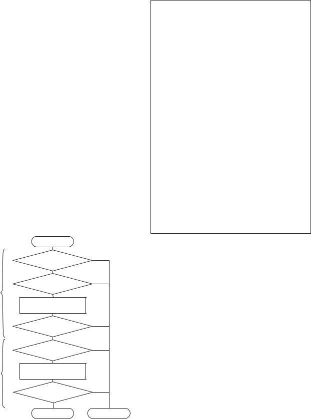
DDX5022/5022Y/5032/5032M/512/52RY
DNX5120/512EX/5220/5220BT
ADJUSTMENT
List of Adjustment and Check Items for DVS-802xV and 812xV
1. Adjustments after replacement of pickup
The mechanism shall be adjusted to reduce variations among parts, which are inherent to the machine.
No. |
Item |
Overview |
Disc |
|
|
|
|
|
|
1 |
Offset Cancel Adjust |
Stray light offset in |
- |
|
the optical module |
||||
|
|
|
||
|
|
|
|
|
|
|
Support recording |
|
|
|
|
of minimum limit for |
|
|
2 |
Inner Limit Adjust |
DVD+R/RW |
- |
|
|
|
(To decide the focus |
|
|
|
|
on position.) |
|
|
|
|
|
|
|
|
|
To decide focus on |
TCD-782 |
|
3 |
Focus Height Adjust |
drive such that the |
||
pickup lens shall not |
TCDR-704 |
|||
|
|
|||
|
|
hit on the disc. |
|
|
|
|
|
|
2. Contents to be checked
No. |
Item |
Overview |
Overview |
|
|
|
|
|
|
1 |
Check CD playback |
TCD-782 (TNo.1, 23) |
TCD-782 |
|
Dropout of sound |
(Any CD-DA) |
|||
|
|
|||
|
|
|
|
|
|
|
Any irregularities of |
|
|
2 |
Check DVD playback |
images or dropout of |
Any DVD-Video |
|
|
|
sound |
|
|
|
|
|
|
3. Adjustment procedure
Test Mode
Normal Mode
Start of adjustment |
|
Is the offset cancel completed |
No |
|
|
successfully? |
|
Yes |
|
Is the adjustment of inner limit |
No |
completed successfully? |
|
Yes |
|
Adjustment of focus height |
|
Insert TCD-782 or TCDR-704. |
|
Is the adjustment of focus height |
No |
completed successfully? |
|
Yes |
|
CD (TCD-782) |
No |
|
|
Playback, OK? |
|
Yes |
|
Change Disc |
|
CD-DA → DVD-Video |
|
DVD-Video (Any) |
No |
Playback, OK? |
|
Yes |
|
End |
Error |
“Test Mode”
Adjustments q through e shall be made in DVS-8000 Adjust of the Test mode.
[Service] → [DVS-8000] → [DVS-8000 Adjust]
qOffset Cancel
Condition: Run the cancel operation only when there is no disc in the unit.
Criteria: The “OK” shall be shown.
wInner Limit SW Adjustment
Condition: Make the adjustment regardless of the disc is inserted in the unit or not.
Criteria: The “OK” shall be shown.
eAdjustment of Focus Height
Condition: Make the adjustment when the disc (CD) is inserted in the unit
Criteria: The “OK” shall be shown.
“Normal Mode”
Run checks r and t in the Normal mode that is transferred by Power OFF → ON.
rCheck that CD can be played back. Criteria: CD shall be played back normally.
tCheck that DVD can be played back. Criteria: DVD shall be played back normally.
4. Contents of Failure
No. |
Contents of Failure |
Major cause |
|
|
|
|
|
|
|
• CD and/or LD does not turn on |
|
1 |
Failure in adjustment of |
(Short in soldering) |
|
focus height |
• Connector (Pick, Spindle) |
||
|
|||
|
|
• Failure in spindle |
|
|
|
|
|
|
Failure in inner limit |
• Connector (Spindle) |
|
2 |
• Abnormal sled |
||
adjustment |
|||
|
• Inner limit SW does not turn on. |
||
|
|
||
|
|
|
|
3 |
Operation Check |
• Disc scratch, Dirt, Pick |
|
|
|
|
24
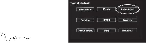
1. Flicker adjustment
●Condition
Video source: Video
Video: Luster white 30%~50% BRIGHT: MAX
DDX5022/5022Y/5032/5032M/512/52RY
DNX5120/512EX/5220/5220BT
ADJUSTMENT
2. VCOM Amplitude and AGC and WB Au-
tomatic adjustments
●Adjustment conditions
Input signal: Input white 100% (NTSC) in R-CAM.
MODE: FULL
● Adjustment procedure
qDisplay luster white 30%~50%.
wPlace a flicker adjustment jig to the monitor and observe the waveform with an oscilloscope.
eTurn X35-489: VR200 and adjust to make the amplitude of the waveform to minimum.
● Adjustment Method
qPress Auto Adjust on the Test Mode Main screen.
Oscilloscope range: 20mV, 0.5mS
● Note
qIn checking the screen after the adjustment, move the monitor up and down in order to confirm that the screen does not flicker. (This check is also carried out on the 07 model.)
wNoise due to AC200V can be observed in the flicker adjustment jig and oscilloscope and thus carefully set up the power supply and GND of the jig and oscilloscope.
In 07 model, GND of the measurement equipment has been floated.
wAfter the automatic adjustment, “Auto Set OK” will be shown to indicate the completion of the adjustment.
3. Adjustment of Horizontal display start position and pixel
●Video displayed on Adjustment screen
GRAPHIC : Special screen used only for adjustment (See below)
DNX_NAVI : Special screen used only for adjustment of GARMIN (See below)
DDX_NAVI : Input KNA-G520.
●GRAPHIC
Pixel Adjustment key (DOT_PHASE): Adjustment of horizontal display position of pixel (Default: 32)
Screen Position Adjustment key (HPOSI): Adjustment of horizontal display starting position of the entire screen (Default: 0)
Display Range Adjustment key (DOT_FREQ): Adjustment of horizontal display range of the video (Default: 64)
25
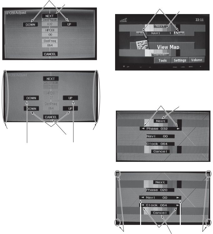
DDX5022/5022Y/5032/5032M/512/52RY
DNX5120/512EX/5220/5220BT
ADJUSTMENT
• GRAPHIC Adjustment screen |
• NAVI Adjustment screen |
|
|
Pixel Adjustment key |
DDX |
|
|
Proceed to the next |
Screen Position |
|
|
adjustment screen. |
Proceed to the next |
||
Adjustment key |
|||
|
adjustment screen |
||
|
|
DNX
Procedure to display NAVI Adjustment screen q Start the set.
w Connect special jig on MINI_USB of NAVI.
Pixel Adjustment key
Horizontal |
Display Range |
Horizontal |
|||
Adjustment key |
Screen Position |
||||
Screen Position |
|||||
|
Return to the Menu |
Adjustment OSD |
|||
Adjustment OSD |
|
||||
|
|
Screen Position |
|
||
|
|
Adjustment key |
|
|
|
|
|
|
|||
● NAVI
Pixel Adjustment key (DOT_PHASE): Adjustment of horizontal display position of pixel (Default: 32)
Screen Position Adjustment key (HPOSI): Adjustment of horizontal display starting position of the entire screen (Default: 0)
Display Range Adjustment key (DOT_FREQ): Adjustment of horizontal display range of the video (Default: 64)
Proceed to the next adjustment screen
|
Display Range |
|
||
Horizontal |
Adjustment key |
Horizontal |
||
Screen Position |
|
Return to the |
Screen Position |
|
Adjustment OSD |
|
Menu screen |
Adjustment OSD |
|
|
|
Screen Position |
|
|
|
|
Adjustment key |
|
|
26
Loading...