


AV CONTROL CENTER
C-V750
INSTRUCTION MANUAL
KENWOOD CORPORATION
B60-3214-00 CH (T) MC
98/12 11 10 9 8 7 6 5 4 3 2 1 97/12 11 10 9 8 7 6
Before applying power
|
Before applying power |
C-V750 (En/T) |
||
2 |
3Caution : Read this section carefully to ensure safe operation. |
|||
|
|
|
|
|
Units are designed for operation as follows. |
|
|
||
|
|
|
||
|
Europe and U.K. .............................................. |
AC 230 V only |
||
For the United Kingdom
Factory fitted moulded mains plug
1.The mains plug contains a fuse. For replacement, use only a 13-Amp ASTA-approved (BS1362) fuse.
2.The fuse cover must be refitted when replacing the fuse in the moulded plug.
3.Do not cut off the mains plug from this equipment. If the plug fitted is not suitable for the power points in your home or the cable is too short to reach a power point, then obtain an appropriate safety approved extension lead or adapter, or consult your dealer.
If nonetheless the mains plug is cut off, remove the fuse and dispose of the plug immediately, to avoid a possible shock hazard by inadvertent connection to the mains supply.
IMPORTANT: The wires in the mains lead are coloured in accordance with the following code:
Blue: Neutral
Brown: Live
Do not connect those leads to the earth terminal of a three-pin plug.
Safety precautions
3Caution : Read this section carefully to ensure safe operation.
WARNING : TO PREVENT FIRE OR ELECTRIC SHOCK, DO NOT EXPOSE THIS APPLIANCE TO RAIN OR MOISTURE.
CAUTION
RISK OF ELECTRIC SHOCK
DO NOT OPEN
CAUTION: TO REDUCE THE RISK OF ELECTRIC SHOCK, DO NOT REMOVE COVER (OR BACK). NO USER-SERVICEABLE PARTS INSIDE, REFER SERVICING TO QUALIFIED SERVICE PERSONNEL.
THE LIGHTNING FLASH WITH ARROWHEAD SYMBOL, WITHIN AN EQUILATERAL TRIANGLE, IS IN-
TENDED TO ALERT THE USER TO THE PRESENCE OF UNINSULATED “DANGEROUS VOLTAGE” WITHIN
THE PRODUCT’S ENCLOSURE THAT MAY BE OF SUFFICIENT MAGNITUDE TO CONSTITUTE A RISK OF
ELECTRIC SHOCK TO PERSONS.
THE EXCLAMATION POINT WITHIN AN EQUILATERAL TRIANGLE IS INTENDED TO ALERT THE USER TO
THE PRESENCE OF IMPORTANT OPERATING AND MAINTENANCE (SERVICING) INSTRUCTIONS IN THE
LITERATURE ACCOMPANYING THE APPLIANCE.
Unpacking
Unpack the unit carefully and make sure that all accessories are put aside so they will not be lost. Examine the unit for any possibility of shipping damage. If your unit is damaged or fails to operate, notify your dealer immediately. If your unit was shipped to you directly, notify the shipping company without delay. Only the consignee (the person or company receiving the unit) can file a claim against the carrier for shipping damage. We recommend that you retain the original carton and packing materials for use should you transport or ship the unit in the future.
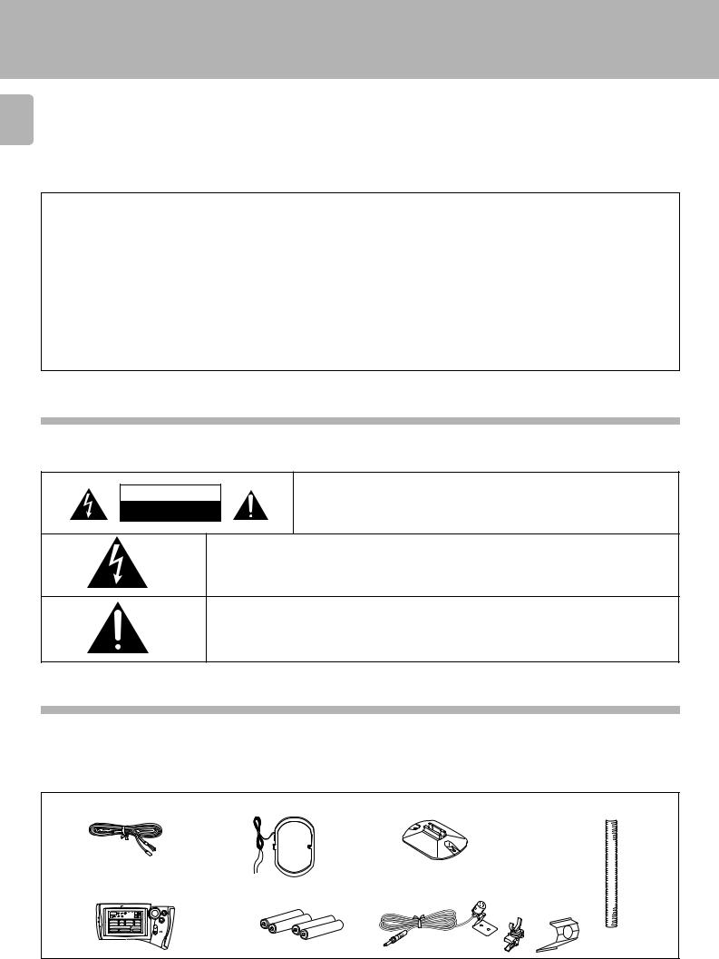
Accessories
FM indoor antenna (1) |
AM loop antenna (1) |
Loop antenna stand (1) |
Cable tidy (2) |
Graphical Remote Control unit (1) |
Batteries(R03/AAA) (4) |
Microphone (1) |
||
Setup |
|
|
|
|
C D |
L D Tape1 VCR1 |
|
|
|
Sat. |
T V Cable |
VCR2 |
|
|
DVD/6ch Input |
|
|
|
|
Sound Speaker |
Reset |
|
|
|

|
Before applying power |
|
|
|
C-V750 (En/T) |
Contents |
Caution : Read the pages marked 3carefully to ensure safe operation. |
|
|
|
3 |
Before applying power .............................................................................................................................................................................................. |
|
2 |
|
3Before applying power ................................................................................................................................. |
2 |
|
3Safety precautions ........................................................................................................................................ |
2 |
|
Unpacking ........................................................................................................................................................... |
2 |
Contents ........................................................................................................................................................................................................................ |
|
3 |
Special features .......................................................................................................................................................................................................... |
|
4 |
System connection ..................................................................................................................................................................................................... |
|
5 |
|
Connection of audio components (CD player, cassette deck, power amplifier) ............................................... |
5 |
|
Connection of video components (LD player, VCR, cable/satellite tuner, DVD) ............................................... |
6 |
|
Digital connections ............................................................................................................................................ |
7 |
|
About the system control connections .............................................................................................................. |
8 |
|
Connection of flat-cable connector ................................................................................................................... |
8 |
|
Connection of antenna ....................................................................................................................................... |
9 |
Controls and indicators ........................................................................................................ |
.................................................................................. |
10 |
Setup of the Graphical Remote Control (GRC) unit ........................................................................................................................................... |
12 |
|
|
Controls and indicators .................................................................................................................................... |
12 |
|
Setting up the GRC according to your AV CONTROL CENTER (Model Type Setup) ....................................... |
13 |
|
Setting up the GRC according to the option components (Set Up) ...................................................................... |
14 |
|
Setting up the GRC according to other components (Set Up) ...................................................................... |
... 15 |
Remote control of components from the GRC .................................................................................................................................................... |
16 |
|
|
Controlling the AV CONTROL CENTER ............................................................................................................. |
16 |
|
Controlling the components connected through system control cords .......................................................... |
17 |
Convenient functions ............................................................................................................................................................................................... |
|
19 |
|
One-touch operation and easy operation features ................................................................................ |
......... 19 |
System component startup by voice activation ................................................................................................................................................. |
20 |
|
|
Starting the system components by voice activation (by any person) ........................................................... |
20 |
|
Auto power-save .............................................................................................................................................. |
20 |
|
Recording the user’s own voice for voice activation (by specific person) ...................................................... |
21 |
|
Starting the system by voice activation using the recorded words (by specific person) ............................... |
21 |
Playing music .................................................................................................................. |
......................................................................................... |
22 |
Sound adjustment functions ..................................................................................................... |
............................................................................. |
23 |
Recording ...................................................................................................................... |
............................................................................................ |
25 |
Broadcast reception ............................................................................................................ |
................................................................................... |
26 |
|
Receiving broadcast station ............................................................................................................................. |
26 |
RDS (Radio Data System) ........................................................................................................ |
............................................................................... |
27 |
|
Functions of RDS .............................................................................................................................................. |
27 |
|
DISPLAY key ..................................................................................................................................................... |
27 |
|
RT key ............................................................................................................................................................... |
27 |
|
Storing RDS stations automatically in preset memory (AUTO MEMORY) ..................................................... |
28 |
|
Receiving a preset RDS station ....................................................................................................................... |
28 |
|
Storing radio stations manually in preset memory ............................................................................... |
.......... 29 |
|
Receiving a preset station ............................................................................................................................... |
29 |
|
Receiving all preset stations in order (P. CALL) ............................................................................................... |
29 |
|
Searching for a desired program type (PTY search) .............................................................................. |
.......... 30 |
|
Reserving reception of desired kind of programme in advance (EON reservation) ....................................... |
32 |
|
To cancel EON reservation ............................................................................................................................... |
33 |
Ambience effects ...................................................................................................................................................................................................... |
|
34 |
|
Sound modes .................................................................................................................................................... |
34 |
|
Setup for surround play .................................................................................................................................... |
36 |
|
Surround play ................................................................................................................................................... |
38 |
|
Surround play of LD or DVD ............................................................................................................................. |
39 |
|
Setup for surround play (while listening to music) ......................................................................................... |
40 |
|
Setup of other speakers than those used by system SERIES 21 .................................................................... |
44 |
|
Setup of the surround effect parameters (DSP) .............................................................................................. |
46 |
Clock adjustment ...................................................................................................................................................................................................... |
|
48 |
|
Displaying the Time .......................................................................................................................................... |
48 |
Timer operation ......................................................................................................................................................................................................... |
|
49 |
|
Timer programming .......................................................................................................................................... |
49 |
|
Activating the timer ......................................................................................................................................... |
51 |
|
Sleep timer ....................................................................................................................................................... |
52 |
Set up code chart ...................................................................................................................................................................................................... |
|
53 |
|
VCR Set up codes ............................................................................................................................................. |
53 |
|
TV Set up codes ................................................................................................................................................ |
54 |
|
TV Set up codes ................................................................................................................................................ |
55 |
|
LD Set up codes ................................................................................................................................................ |
55 |
|
Satellite Set up codes ...................................................................................................................................... |
56 |
|
Cable Set up codes ........................................................................................................................................... |
56 |
Specifications ..................................................................................................................................................................................................... |
|
57 |
In case of difficulty .................................................................................................................................................................................................. |
|
58 |
Special features
C-V750 (En/T)
4 Special features
True home theater sound
Dolby Digital (AC-3)
The DOLBY DIGITAL (AC-3) mode lets you enjoy full digital surround from software processed in the Dolby Digital (AC-3) format. Dolby Digital (AC-3) provides up to 5.1 channels of independent digital audio for better sound quality and more powerful presence than conventional Dolby Surround.
Dolby Pro Logic & Dolby 3 Stereo
This surround system reproduces theater-like surround sound from video software marked 
 .
.
The PRO LOGIC mode uses the built-in adaptive matrix circuit to steer the Left, Center, Right and Surround channel audio signals. The 3 STEREO mode will redirect the surround signal to the front left and right speakers when only the front and center speakers are used.
New DSP surround modes
The DSP (Digital Signal Processor) used for this AV CONTROL CENTER incorporates a variety of high quality adjustable sound fields, like "ARENA", "JAZZ CLUB", "STADIUM", "CATHEDRAL" and "THEATER", to add the “presence” associated with an arena, jazz club or stadium (etc.) to the original signal. It is compatible with almost any kind of program source.
Graphical Remote Control unit ”GRC”
The GRC unit incorporates a large-screen LCD which displays key icons and parameters. The LCD also shows information on the operating modes of the main unit.
To improve the operability, frequently used icons are located in the higher hierarchy in the LCD display and icons which are associated between each other are shown on the same screen.
The GRC unit is a multi-function remote control unit which can be programmed to control AV components from other manufacturers than KENWOOD.
RDS (Radio Data System) tuner
This AV CONTROL CENTER is equipped with a RDS tuner that provides several convenient tuning functions: AUTO MEMORY, to automatically preset up to 40 RDS stations broadcasting different programs; station name display, to show you the name of the current broadcast station; and PTY search to let you tune stations by program type.
ONE TOUCH OPERATION
Simply pressing the play key of the CD player or cassettedeck turns the system on and starts playback.
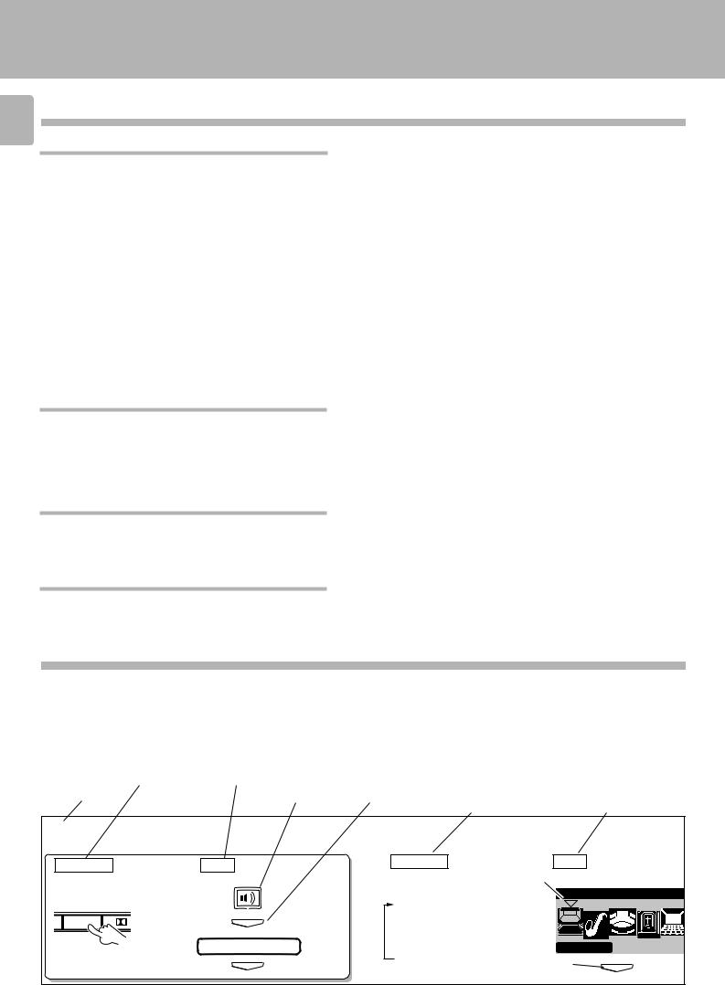
How to use this manual
In this manual, the operating procedures are described on the left half of each page and the supplementary explanation, display information and other notes on each step are described on the right half.
(Example of instructions in this manual) |
|
|
|
||||
Operating procedure steps (Left half) |
Supplementary explanation (Right half) |
||||||
|
|
|
|
|
|
|
|
|
Main unit key to be |
|
Remote control key to |
|
|
|
|
|
used |
|
be used |
|
|
|
Supplementary |
Step No. |
Icon selection |
Press ENTER key. |
Supplementary |
explanation for the |
|||
explanation for the main |
graphical remote |
||||||
|
|
|
|
|
|
unit operation |
control operation |
1Select the DSP surround mode.
Main unit |
GRC |
|
1 Select DSP. |
O DSP |
ENTER |
|
DSP Mode |
|
ENTER |
Main unit |
GRC |
|
Each press switches |
1 Selection cursor |
|
|
|
|
the indication. |
Sound DSP Mode |
|
1 ARENA |
|
|
2 JAZZ CLUB |
|
|
3 STADIUM |
|
|
4 CATHEDRAL |
Arena |
|
5 THEATER |
|
|
2 Entry |
|
|
|
ENTER |
|

System connection
C-V750 (En/T) |
|
|
Connection of audio components (CD player, cassette deck, power amplifier) |
5 |
|
|
|
|
|
|
|
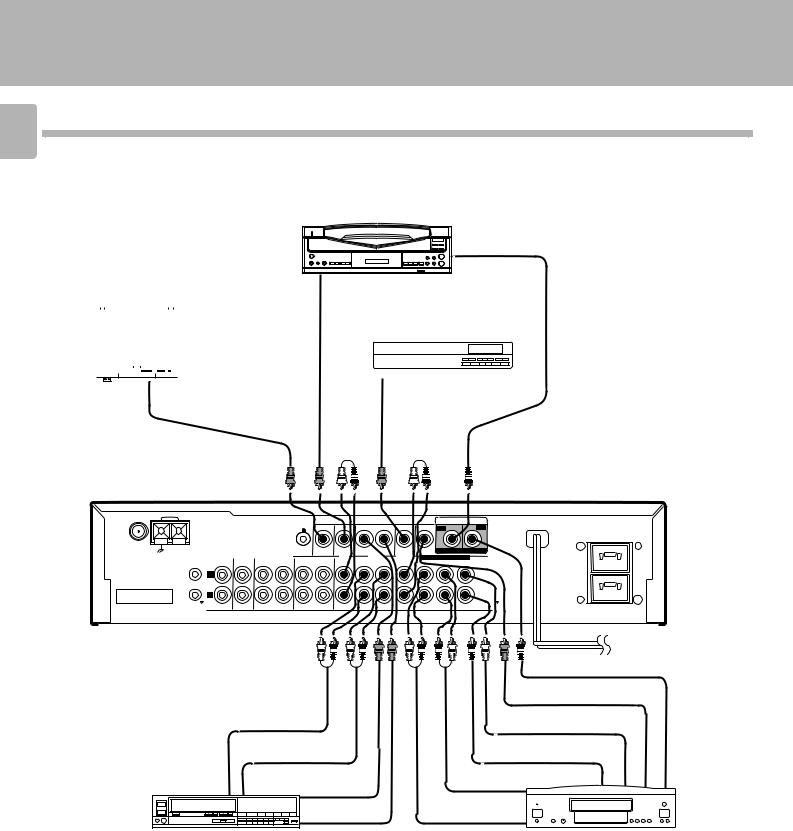
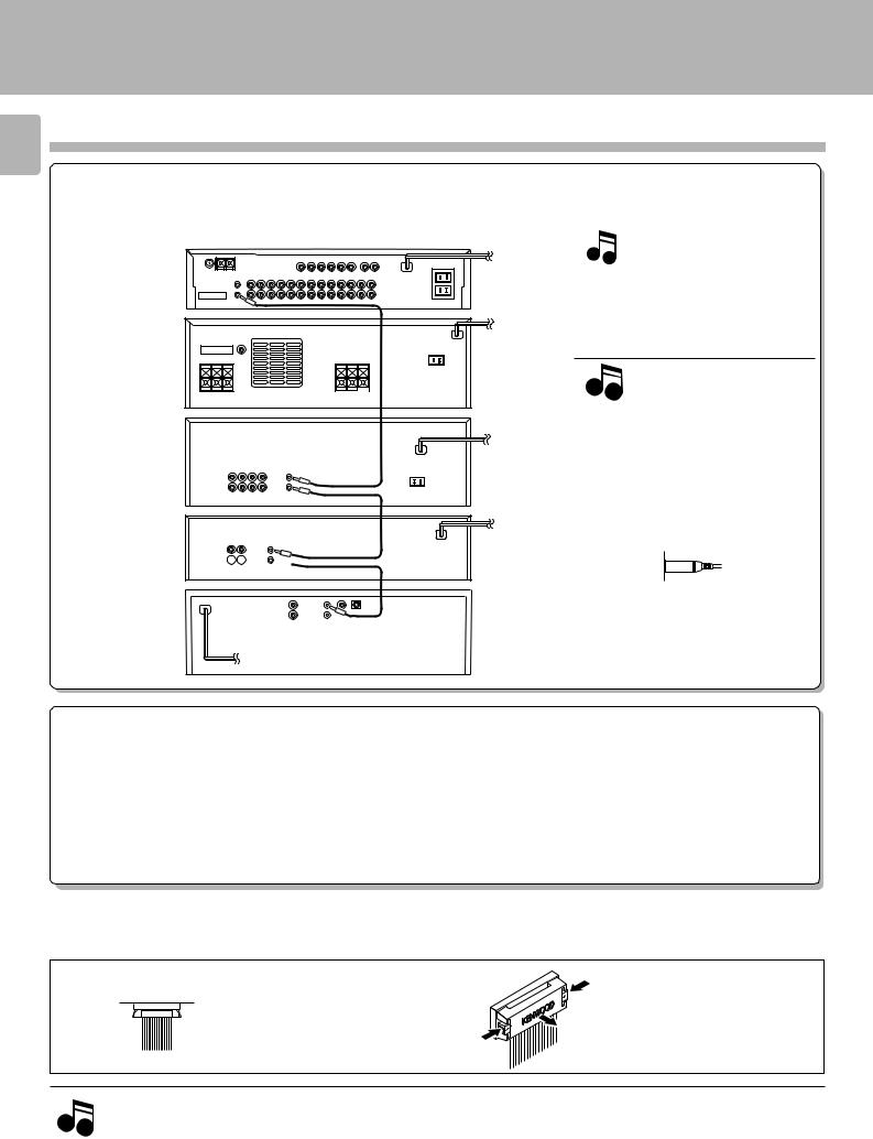
Make connection as shown below.
When connecting the related system components, refer
Malfunction of microcomputer
also to the instruction manuals of the related components.
3Do not plug in the power lead until all connections are completed.
Analog disc turntable
(with built-in equalizer amp)
Voice-activation microphone
If operation is not possible or erroneous display appears even though all connections have been made properly, reset the microcomputer referring to “In case of difficulty”. I
Shape of AC outlet
ANTENNA |
AM |
|
|
|
VOICE |
|
VIDEO |
|
AC-3 AUDIO INPUT |
|
|
|
|
|
|
ACTIVATE |
|
|
|
LD |
DVD |
|
|
|
|
|
|
|
|
|
||
FM 75Ω |
|
|
|
|
MONITOR |
|
|
|
|
|
GND |
|
|
|
|
|
|
CABLE |
DIGITAL IN DIGITAL IN |
||
|
|
|
|
|
OUT |
LD |
VCR |
DVD 6CH.INPUT |
||
|
SYSTEM |
CD |
AUX |
TAPE 1/ MD |
TAPE 2 |
/ SAT. |
||||
|
|
|
|
CENTER |
||||||
|
(MONITOR) |
|
|
|
|
|||||
|
CONTROL |
|
|
|
|
|
|
|
|
|
CONNECT WITH |
|
L |
|
|
|
|
|
|
|
|
|
|
|
|
|
|
|
|
|
|
|
POWER AMPLIFIER |
|
|
|
|
|
|
|
|
|
|
|
|
R |
|
|
|
|
|
|
|
|
|
|
IN |
IN |
REC PLAY |
REC PLAY IN |
REC PLAY |
IN FRONT SURROUND SUBWOOFER |
|||
AUDIO
|
PLAY |
*2 Cassette deck 2 |
|
|
OUT |
|
|
|
REC IN |
|
|
REC |
PLAY |
Cassette deck 1 |
|
IN |
OUT |
||
or MD recorder |
|||
|
|
U.S.A.,Canada
and China
Australia
Other countries
UNSWITCHED CAUTION(ForU.K.)
When using the AC outlets equipped with this unit, be sure to consult your dealer for the corresponding plug.
To wall
AC outlet
System control cord
|
LINE |
CD player |
|
OUTPUT |
|
|
|
|
Connection |
System |
|
control cord |
|
|
cable |
|
|
|
|
*1 Power amplifier M-A300
*1 For the connection and operation procedures of the power amplifier and speakers, refer to the instruction manual of the power amplifier (M-A300).
The connected components shown here are given as examples because the available models vary depending on marketing areas.
Also connect the system control cords when the KENWOOD Audio Component System “SERIES 21” is connected.
*2 Do not connect system control cord to the cassette deck connected to the TAPE 2 (MONITOR) jacks.
Caution regarding placement
To maintain proper ventilation, be sure to leave a space around the unit (from the largest outer dimensions including projections) equal to, or greater than, shown below.
Left and right panels: 10 cm
Rear panel |
: 10 cm |
Top panel |
: 50 cm |
System connection
C-V750 (En/T)
6 Connection of video components (LD player, VCR, cable/satellite tuner, DVD)
LD player
|
|
|
|
|
|
Video |
Audio |
|
|
|
RF |
*1 |
|
|
|
|
|
|
|
|
OUT |
|
|
|
|
||||
Monitor TV |
|
OUT |
|
|
|
DEMO- |
|
*1 AC-3 RF Demodulator |
||||||
|
|
|
|
|
|
DURETER |
|
|||||||
|
|
|
|
|
|
|
|
|
|
|
|
|
7 |
|
|
|
|
|
|
|
|
|
|
|
|
||||
|
|
|
|
|
|
|
CABLE/SATELLITE |
|
||||||
|
|
|
|
|
|
|
|
|
||||||
|
|
|
|
|
|
|
|
|
|
|
|
|
|
|
|
|
|
|
|
|
|
|
|
|
|
|
|
|
|
|
|
|
|
|
|
|
|
|
|
|
|
|
|
|
|
|
|
|
|
|
|
|
|
|
|
|
|
|
|
|
|
|
|
|
|
|
|
|
|
|
|
|
|
|
|
|
|
|
|
|
|
|
|
|
|
|
|
|
|
|
|
|
|
|
|
|
|
|
|
|
|
|
|
|
|
|
Video |
|
|
|
Video |
Audio |
|
|
|||||
|
|
IN |
|
|
|
OUT |
OUT |
|
|
|||||
|
|
|
|
|
|
|
|
|
|
|
|
|
|
|
ANTENA |
AM |
VOICE |
VIDEO |
AC-3 AUDIO INPUT |
|
|
ACTIVATE |
||
|
|
|
|
LD |
DVD |
UNSWITCHED |
FM 75Ω
GND |
|
MONITOR |
|
|
CABLE |
DIGITAL IN DIGITAL IN |
|
|
OUT |
LD |
VCR |
DVD 6CH.INPUT |
|
SYSTEM |
CD AUX TAPE 1/ MD |
TAPE 2 |
/ SAT. |
|||
(MONITOR) |
|
|
|
CENTER |
||
CONTROL |
|
|
|
|
|
|
L
CONNECT WITH
POWER AMPLIFIER
R
IN |
IN |
REC PLAY REC PLAY IN |
REC PLAY IN FRONT SURROUND SUB WOOFER |
AUDIO
Audio DIGITAL OUT
|
|
|
Video OUT |
|
Audio IN |
|
Audio CENTER OUT |
|
|
|
|
|
Audio OUT |
|
Audio SUBWOOFER OUT |
|
|
|
|
|
|
Video IN |
Audio SURROUND OUT |
|
|
|
|
|
|
Video OUT |
Audio FRONT OUT |
|
|
|
|
VCR |
|
|
DVD |
The connected components are given as examples because the available models vary depending on marketing areas.
Digital connections
System connection
C-V750 (En/T)
7
Make connections as shown below.
The digital in jacks can accept either Dolby Digital (AC-3) or PCM signals (the input signal type is detected automatically). When connecting the related system components, be sure to also refer to the instruction manuals supplied with the components you are connecting.
Do not connect the power cord to a wall outlet until all connections are completed.
Connect components capable of outputting Dolby Digital (AC-3) or standard PCM format digital signals.
Orange RCA pin cord
VOICE |
|
VIDEO |
|
AC-3 AUDIO INPUT |
|
ACTIVATE |
|
|
|
LD |
DVD |
|
|
|
|
||
MONITOR |
|
|
CABLE |
DIGITAL IN DIGITAL IN |
|
OUT |
LD |
VCR |
DVD 6CH.INPUT |
||
TAPE 2 |
/ SAT. |
||||
(MONITOR) |
|
|
|
|
CENTER |
REC PLAY IN |
REC PLAY |
IN FRONT SURROUND SUBWOOFER |
|||
AUDIO
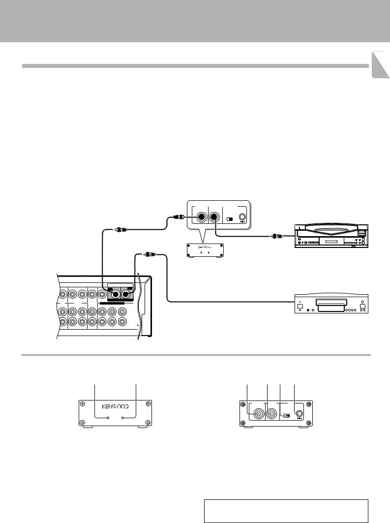
To connect an LD player with a DIGITAL RF OUT.
Connect the LD player to the KENWOOD RF digital demodulator (DEM-999D). Then connect the demodulator to the AC-3 AUDIO INPUT DIGITAL IN.
Connect the video signal and analog audio signals to LD jacks (See "Connection of video components".)
AC-3 DIGITAL |
|
AC-3 RF |
|
DC IN |
OUTPUT |
|
INPUT |
|
12V |
OFF ON
@ #
AC-3 RF OUT (AUDIO) 
RCA pin cord
LASER DISC RF DEMODULATOR DEM-999D
POWER LOCK
AC-3RFDemodulator (DEM-999D)
To connect a DVD player
COAXIAL DIGITAL OUT with a DIGITAL OUT (AUDIO)
Orange RCA pin cord
Connect the video signal and analog audio signals to the DVD jacks.
(See "Connection of video components".)
The connected components are given as examples because the available models vary depending on marketing areas.
AC-3 RF Demodulator DEM-999D
12
LASER DISC RF DEMODULATOR DEM-999D
POWER LOCK
1POWER indicator
Lights (red) when the power switch (5) is set to ON .
2LOCK indicator
Lights when an AC-3 RF signal is input to the AC-3 RF INPUT jack (4).
3AC-3 DIGITAL OUTPUT (coaxial)
Connect this jack to the LD, AC-3 AUDIO INPUT (DIGITAL), jack on your AV CONTROL CENTER.
It outputs AC-3 coaxial digital signals when the POWER (5) is set to ON and an AC-3 RF signal is input to the AC-3 RF INPUT jack (4).
34 5 6
AC-3 DIGITAL |
AC-3 RF |
DC IN |
OUTPUT |
INPUT |
12V |
OFF ON
@ #
EXTERNAL DC SUPPLY DC 12V
4AC-3 RF INPUT
Connect this jack to the AC-3 RF OUTPUT jack on your LD player.
5POWER switch
Use to switch the power ON/OFF.
6DC IN (12V) jack
Connect this jack and inlet power cord to the AC adaptor supplied with your demodulator. Connect the power cord to a wall outlet after completing all of the other connections.
Place the power supply away from the demodulator, AV CONTROL CENTER, and any antennas.
System connection
C-V750 (En/T)
8 About the system control connections
When this unit is connected to KENWOOD audio component system “SERIES 21”, also connect them through the system control cords to allow system-control operations between components.
Connection example
AV |
SYSTEM |
CONTROL |
|
CONTROL |
|
CENTER |
|


 System POWER
  control cord
AMPLIFIER
SYSTEM
CONTROL
GRAPHIC
EQUALIZER
SYSTEM
CONTROL System
CASSETTE 

 control cord
DECK
System
SYSTEM control cord
CONTROL
CD
PLAYER
The SERIES 21 components which can be system-connected with this unit include the LD player, MD recorder and DVD player.
Notes
1.Do not connect the SERIES 21 components to other system components using system control cords.
2.Do not connect system control cords to any components other than those specified by KENWOOD. It may cause a malfunction and damage your equipment.
3.Be sure the system control plugs are inserted all the way in to the system control terminals.
About the system control operations
(Available operations when SERIES 21 components are connected through system control cords)
Remote Control
Lets you operate source components with the system remote supplied with this unit.
Automatic Operation
When you start playback from a source component, the input selector on this unit switches to that component automatically. (Except TAPE 2)
Synchronized Recording
Lets you synchronize recording with the start of playback when recording from CD, LD or MD.
Connection of flat-cable connector
|
|
Inserting the connector |
Removing the connector |
Push in the connector straight into the socket until it clicks to indicate the locking.
Push and hold the two ends of the connector, and pull it straight outward.
1.Connect all cords firmly. If connections are loose, there could be loss of sound or noise produced.
2.When plugging and unplugging connection cords, be sure to first remove the power cord from the AC outlet. Plugging / unplugging
Notes |
connection cords without removal of the power cord can cause malfunctions or damage to the unit. |
|
3.Do not connect up a power source which is larger than that indicated on the socket at the rear of the unit.
4.If the system control cords or audio cords are not connected properly, the remote control or automatic operation between system components will not work properly.
System connection
C-V750 (En/T)
Connection of antenna |
9 |
||
|
|
||
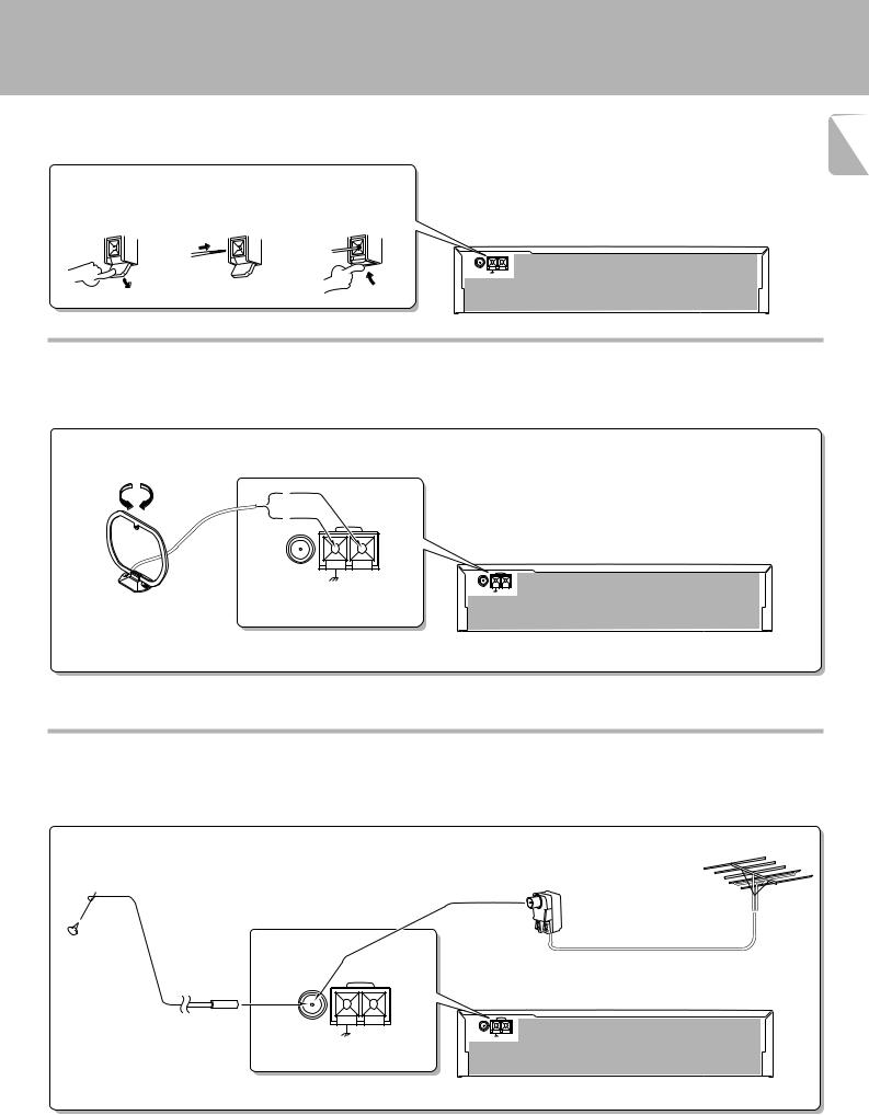
Connection method to each antenna terminal |
|||
|
|||
1 Push lever. |
2 Insert cord. 3 Return lever. |
|
|
ANTENA  AM
AM
FM 75Ω
GND
AM loop antenna connection
The supplied antenna is for indoor use. Place it as far as possible from the main system, TV set, speaker cords and power cord, and set it to a direction which provides the best reception.
ANTENNA |
AM |
FM 75Ω
GND
ANTENA |
AM |
FM 75Ω
GND
FM indoor antenna connection
The accessory antenna is for temporary indoor use only. For stable signal reception we recommend using an outdoor antenna. Remove the indoor antenna if you connect one outdoors.
FM outdoor antenna connection
Lead the 75 Ω coaxial cable connected to the FM outdoor antenna into the room and connect it to the FM 75 Ω terminal.
ANTENNA |
AM |
FM 75Ω
GND
Use the commercially  available antenna adaptor.
ANTENA |
AM |
FM 75Ω
GND
Controls and indicators
C-V750 (En/T)
10
Opening/closing the door
OPEN/CLOSE
Note |
When opening or closing the door, be careful not to catch |
your finger in the door. Otherwise there is a risk of injury. |
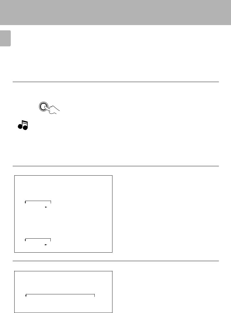
Changing the input selection display (AUTO key)
*1: To change the TAPE 1 display to MD display
1 Select “TAPE 1” with the INPUT SELECTOR .
2Press and hold the AUTO key for more than 2 seconds, until “MD” is displayed.
Each press switches the indication.
1 TAPE1 |
|
2 MD |
|
*2: To change the DVD display to the 6ch INPUT display
1 Select “DVD” with the INPUT SELECTOR .
2Press and hold the AUTO key for more than 2 seconds, until “6 ch INPUT” is displayed.
Each press switches the indication.
To make the system control operation, the input selection display should be switched according to the actually connected components.
About the system control connections |
8 |
1 DVD-A |
|
2 6ch INPUT |
|
Switching the display mode (DISPLAY key)
Use the following procedure to change the display mode.
1 Press the DISPLAY key (remote control only).
Each press switches the indication.
1 INPUT SELECTOR  2 DOLBY/DSP/
  3 Time display STEREO display
display
ÖThe time display is displayed for only 5 seconds, after which the INPUT SELECTOR display appears automatically.
ÖThe display of 2is not shown during SOURCE DIRECT and 6ch INPUT operations.
Controls and indicators
C-V750 (En/T)
RDS indicators |
Frequency display, input |
|
|
|
TAPE 2 indicator |
AUTO tuning mode/ 11 |
||||
(RDS, TP, TA, EON, PTY, NEWS, INFO.) |
selector display, preset |
Decibel indicator |
AC-3 indicator |
|
||||||
|
|
channel display, surround |
|
|
|
|
|
AUTO stereo |
||
|
Memory indicator |
mode display |
Delay time indicator |
DSP indicator |
|
reception indicator |
||||
|
|
|
|
|
|
|
|
|
|
|
|
|
|
|
|
|
|
|
|
|
|
RDS TP |
TA MEMO |
|
|
|
|
|
dB |
|
|
AC-3 |
DSP |
TAPE 2 |
AUTO |
|
|
EON PTY NEWS FM |
|
|
|
|
|
ms |
|
|
|
||||||
|
|
|
|
|
|
PRO LOGIC |
SOURCE |
|
STEREO |
STEREO |
|||||
SLEEP |
INFO. |
|
|
|
|
|
|
|
|
|
|||||
MW |
|
|
|
|
|
kHz |
|
|
|
DIRECT |
|
|
indicator |
||
|
|
|
|
|
|
|
|
|
|
MUTE |
|
||||
TIMER 1 |
2 |
|
|
|
|
|
MHz |
|
3 STEREO |
OVER LEVEL |
TUNED |
||||
LW |
|
|
|
|
|
|
|
||||||||
TIMER |
|
Broadcast band |
|
|
|
|
|
|
3 STEREO |
OVER |
|
TUNED |
|
||
|
|
|
|
|
|
|
indicator |
LEVEL |
|
indicator |
|
||||
indicators |
indicators |
|
|
|
|
|
|
|
|
||||||
|
|
|
|
|
|
|
|
indicator |
|
|
|
||||
|
|
|
|
|
|
|
|
|
|
|
|
MUTE indicator |
|
||
SLEEP TIMER indicator |
|
|
|
|
|
Receiving |
|
|
|
|
|
||||
|
|
|
|
|
|
|
|
|
|
|
|
||||
|
|
|
|
|
|
|
|
frequency |
|
PRO LOGIC |
SOURCE DIRECT indicator |
|
|||
|
|
|
|
|
|
|
|
unit indicators |
|
||||||
|
|
|
|
|
|
|
|
indicator |
|
|
|
||||
|
|
|
|
|
|
|
|
|
|
|
|
|
|
||
|
|
|
|
|
|
Display |
|
|
|
|
|
|
|
|
|
1 2 3 |
4 5 6 7 8 9 0 !@ # |
|
$ |
|
|
|
|||||||||
|
|
|
TIMER |
VOICE |
|
|
|
|
|
|
|
|
|
|
|
|
|
|
ACTIVATE |
|
|
MODE |
MULTI.CONTROL |
|
|
|
|
||||
|
|
|
SET |
CLOCK ON/OFF |
SET |
RT |
|
|
|
|
|
||||
|
|
|
|
|
|
|
|
|
|
|
|
||||
VOICE |
|
|
|
|
STEREO |
DSP |
|
|
LEVEL |
|
|
R D S |
|
|
|
ACTIVATE |
|
TIMER |
|
RDS |
|
|
|
|
|
|
|
|
|
||
|
|
|
|
|
|
|
|
PTY SELECT |
|
|
D I G I T A L |
|
|||
|
|
|
MODE |
S.DIRECT DISPLAY |
PTY |
TA/NEWS/INFO. |
|
|
|
|
|
|
|||
|
|
|
|
|
|
|
|
|
|
|
|
||||
|
|
|
|
|
|
A.MEMO |
AUTO |
BAND |
|
TUNING |
|
|
|
|
|
|
|
|
|
|
|
|
|
|
|
|
|
|
VOLUME CONTROL |
|
|
|
|
|
|
|
|
AV CONTROL CERTER KC-2 |
|
|
|
|
|
|
|
|
|
ON/STANDBY |
|
|
|
|
|
|
|
|
|
|
|
|
|
|
|
PHONES |
INPUT |
TAPE 2 |
|
|
|
|
|
|
|
|
OPEN/CLOSE |
|
|
|
|
|
|
|
|
|
|
|
|
|
|
|
|
|
|
||
|
|
|
(MONITOR) |
|
|
|
|
|
|
|
|
|
DOWN |
UP |
|
%^ |
|
&* ( ) Á ª £ ¢ ° ¤ ¦ |
¥ |
|
|||||||||||
The keys which have the same names as the controls on the remote control unit provide the same functions as them.
1 

 (ON/STANDBY) key
Press to switch between ON and STANDBY.
2VOICE ACTIVATE indicator
Lights to indicate an occurrence of voice activation.
3Remote sensor
4TIMER SET key
Press to set the timer function.
5CLOCK key
Press to set the clock.
6VOICE ACTIVATE ON/OFF key
Press to switch the voice-activation operation ON and OFF.
7VOICE ACTIVATE SET key
Press to record words for use in voice activation.
8RT key
Press to display radio text.
9STEREO key
0DSP key !DOLBY key
@MODE key
Press to switch various setting modes.
#MULTI. CONTROL keys
Press to select various setting modes.
$GRC transmitter
Outputs the signals transmitted to the Graphical Remote Control.
%PHONES jack
For use in headphones listening.
^INPUT SELECTOR key
Press to select the input.
&TAPE 2 (MONITOR) key
For use in monitoring of recording, etc.
*TIMER MODE key
Press to switch the timer modes.
(S.DIRECT key
Press to switch the Source Direct function which allows to reproduce the source with a better quality.
)RDS DISPLAY key
Press to switch the RDS display.
ÁRDS PTY key
For use during reception of RDS broadcasting.
ªRDS TA/NEWS/INFO. key
For use during reception of RDS broadcasting.
£A.MEMO key
Press when using the auto memory function.
¢AUTO key
Press to select the tuning mode.
The auto tuning or manual tuning mode can be selected.
Pressing and holding this key for more than
2 seconds changes the TAPE 1 input display to MD display or the DVD-A input display to
6ch INPUT display. |
0 |
°BAND key
Press to switch the broadcasting band.
¤TUNING keys (  ,
,  )
)
Press to select the radio station to be received.
These keys are also used in the clock adjustment and timer operations.
¦OPEN/CLOSE key
¥VOLUME CONTROL knob
STANDBY mode indication
While standby mode is indicated, a small amount of power is supplied to the system to back up the memory. In this mode, the system can be turned ON by remote control.
With this unit, standby mode is indicated by means of the display panel. The system is in standby mode while the clock display is shown.
Setup of the Graphical Remote Control (GRC) unit
C-V750 (En/T)
12 Controls and indicators
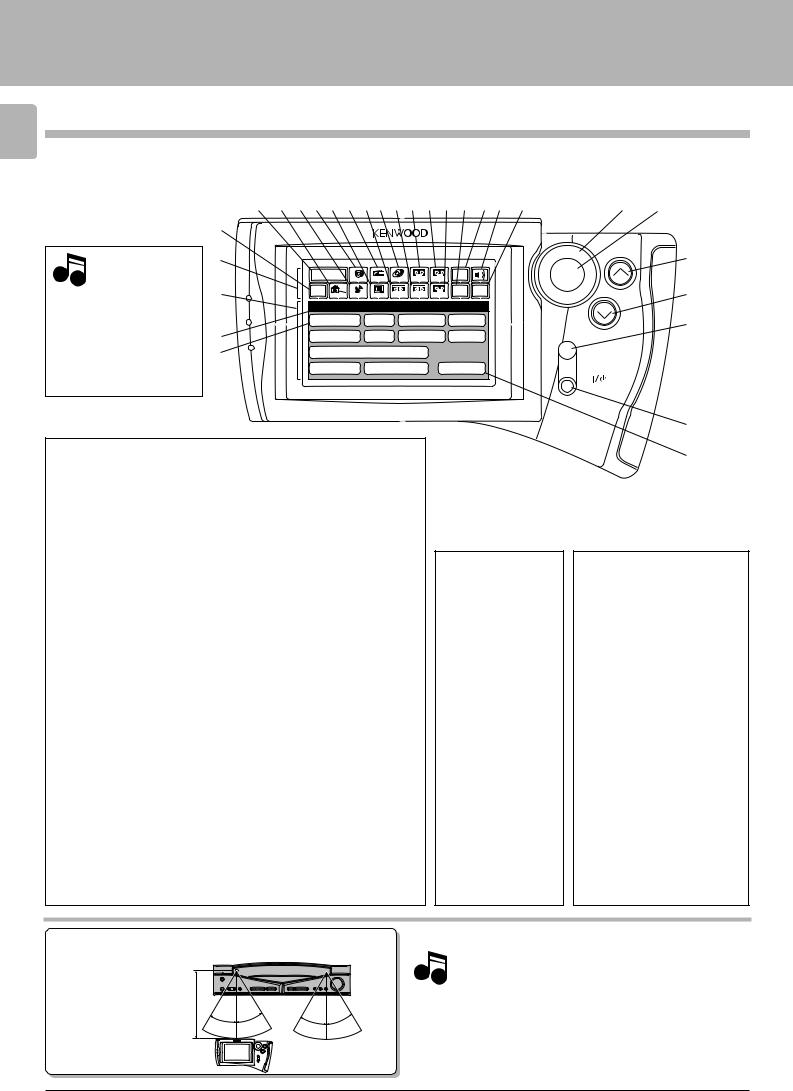
The Graphical Remote Control (GRC) unit provided with the AV CONTROL CENTER can also control KENWOOD cassette decks, CD player and LD player which are connected to it through system control cords. For details of the controllable functions, refer to the instruction manuals of these components.
Model: GRC-150
Infrared system
Note
Perform “Model Type Setup” of the GRC before using it.
|
3 4 5 6 7 8 9 0 ! @ # $ % ^ & * |
£ ¢ |
|
|||||
2 |
|
|
|
|
|
|
|
|
1 |
|
|
|
|
|
|
|
° |
|
|
|
|
|
|
|
|
|
|
Main Menu |
|
|
|
|
Input |
ENTER |
|
|
Tuner |
LD |
Tape1 |
TapeA |
Source |
|
||
|
CD |
|
|
|||||
( |
Return |
|
|
|
|
Set Up Confirm |
VOLUME |
¤ |
Cable Sat. |
TV |
VCR1 |
VCR2 |
TapeB |
|
|||
|
Setup |
|
|
|
|
|
|
|
|
C D |
L D |
Tape1 VCR1 |
|
¦ |
|||
) |
Sat. |
T V |
Cable |
VCR2 |
|
|
||
Á |
DVD/6ch Input |
|
|
MUTE |
|
|||
|
|
|
|
|||||
|
Sound Speaker |
Reset |
|
|
||||
ON/STANDBY
Segment screen
1Segment screen |
#Tape A icon |
This area displays the fixed icons. |
Select to control cassette deck A. |
2Return icon |
$Tape B icon |
Select to return to the previous
display.
3Main Menu icon
Select to change the input source or select Main Menu 2.
4Cable TV icon
Select to control the cable TV.
5Satellite Tuner icon
Select to control the satellite tuner.
6CD icon
Select to control the CD player.
7TV icon
Select to control cassette deck B.
%Set Up icon
Select to make setup operations.
^Input Source icon
Select to switch the input source.
&Sound icon
Select to control the sound-related functions.
*Confirm icon
Select to confirm a setting, etc.
Select to control the TV.
8Tuner icon
Select to control the tuner.
9VCR 1 icon
Select to control VCR 1.
0LD icon
Select to control the LD player.
!VCR 2 icon
Select to control VCR 2.
@Tape 1 icon
Select to control cassette deck 1.
ÖThe input source can be selected using icon 3 or ^.
ÖIcons 4 to $ are used to select the component to be controlled.
¥
ª
Menu screen
(Menu screen
This area displays the control key icons and level information.
)Mode display
The above illustration indicates the Setup mode.
ÁCD icon
Select to set up the CD player.
ªReset icon
Select to return to the “Model Type Setup” menu screen.
Operation keys
£Joystick key
For use in selecting icons.
The joystick moves in 8 directions.
¢ENTER key
Press to enter a selection.
°VOLUME (UP) control key
Press to increase the volume level.
¤VOLUME (DOWN) control key
Press to decrease the volume level.
¦MUTE key
Press to mute sound temporarily.
¥ 

 (ON/STANDBY) key
Press to switch the AV CONTROL CENTER and the components connected to it through system control cords between ON and STANDBY.
Approximate operating range
Infrared remote control
Remote sensor
5m
30° |
30° |
30° |
30° |
GRC or RC
Infrared ray system
1. The supplied batteries are intended for use in operation check. Therefore, their lives may be shorter than ordinary batteries.
Notes 2. When the remote-controllable distance gets shorter than before, replace all four batteries with new ones.
3.Malfunction may occur if direct sunlight or the light of a highfrequency lighting fluorescent lamp enters the remote sensor. In such a case, change the system installation position to prevent the malfunction.
4.The GRC display may show erroneous information when the GRC unit is operated from outside the specified range.
Setup of the Graphical Remote Control (GRC) unit
C-V750 (En/T)
Setting up the GRC according to your AV CONTROL CENTER (Model Type Setup)
13
Perform the following procedure after inserting batteries for the first time and every time after changing them.
Preparation |
Ö Press the |
(ON/STANDBY) key |
|
of the main unit to the ON mode.
ENTER
VOLUME
Model Type Setup
Model 1 |
Model 4 |
Model 2 |
Model 5 |
|
MUTE |
Model 3 |
Model 6 |
|
ON/STANDBY |
Model Type Setup (GRC setup procedure)
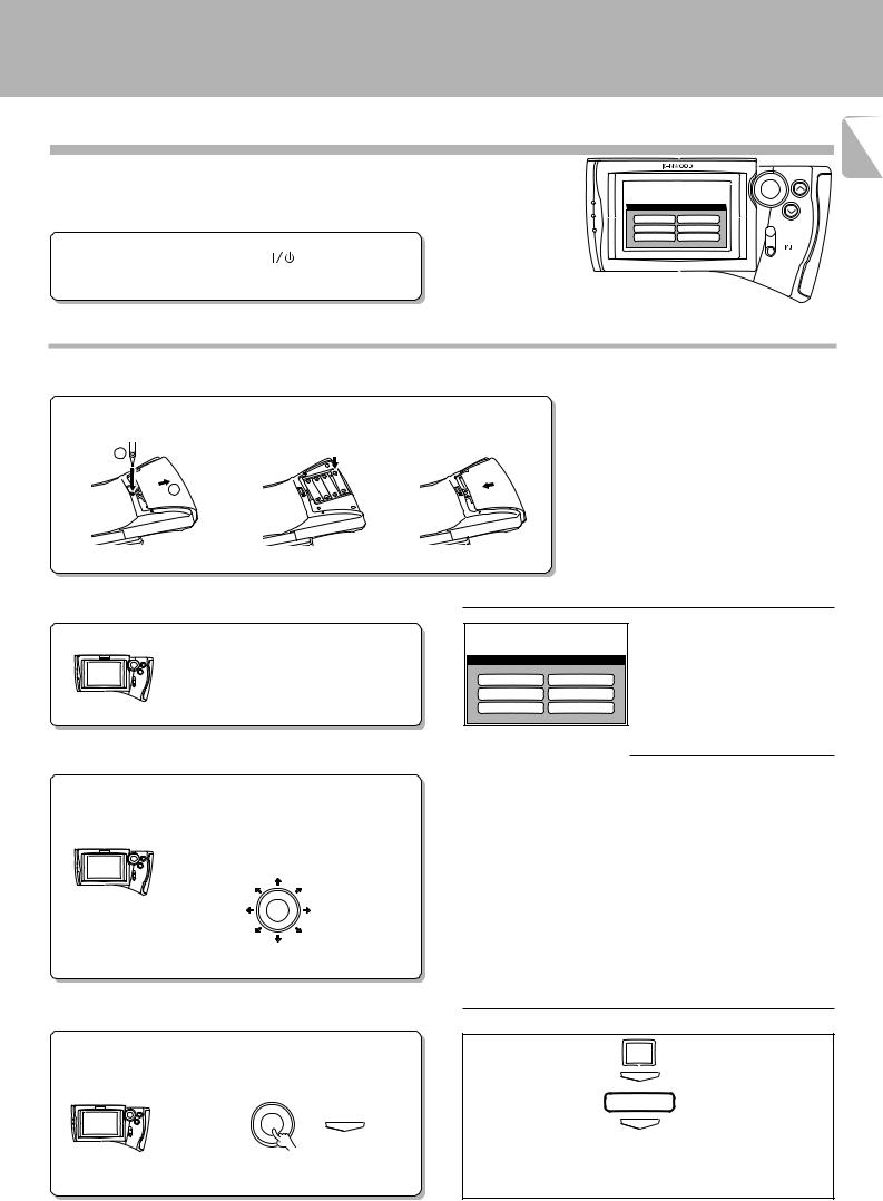
1Loading batteries
1 Remove the cover. |
2 Insert batteries. |
3 Close the cover. |
1 |
|
|
2 |
|
|
Main operation menu
(The displayed icons are variable depending on the model.)
Caution in battery replacement
ÖInsert four AAA-size (R03/UM-4) batteries as indicated by the polarity marking.
ÖTo maintain the memory of the settings you made before, complete the battery replacement operation within 30 seconds.
ÖThe procedure on the left should also be performed when resetting the GRC (as a measure against its malfunction). However, in this case, wait for about five minutes after removing the batteries and before re-inserting them.
2Check the display.
The “Model Type Setup” screen appears.
Model Type Setup
Model 1 |
Model 4 |
Model 2 |
Model 5 |
Model 3 |
Model 6 |
3Move the cursor to the Model type icon matching the AV CONTROL CENTER.
1Identify the model type.
(use the table on the right).
2 Move the cursor.
It can be moved in 8 directions depending on how you press the joystick key.
ENTER
The icon on which the cursor is moved blinks in reverse video.
AV CONTROL CENTER |
GRC |
Model |
“Model Type Setup” icon |
C-V100 ............................................... |
Model 1 |
C-V150 ............................................... |
Model 1 |
C-V300 ............................................... |
Model 2 |
C-V350 ............................................... |
Model 2 |
C-V500 ............................................... |
Model 3 |
C-V550 ............................................... |
Model 4 |
C-V700 ............................................... |
Model 4 |
C-V750 ............................................... |
Model 4 |
C-V770 ............................................... |
Model 3 |
4Enter the selection. |
|
To change Model Type Setup |
|
|
|
||
|
|
1 Select Set Up. |
Set Up |
Press the ENTER key. |
|
2 Press the ENTER key. |
ENTER |
|
|
||
|
|
3 Select Reset. |
Reset |
ENTER |
ENTER |
4 Press the ENTER key. |
ENTER |
|
|
5 Perform the setup procedure from step ”2Check the display”. |
|
|
|
Ö The above operation clears all of the previously made settings and |
|
|
|
resets the unit to the initial condition. |
|
Setup of the Graphical Remote Control (GRC) unit
C-V750 (En/T)
14 Setting up the GRC according to the option components (Set Up)
The following procedures prepare the GRC for operating the components connected through system control cords. Make sure that these components are connected through system
control cords. |
8 |
ÖIf you proceed to the following “Set Up” operations immediately after steps 1to 4of “Model Type Setup (GRC setup procedure)” on page #, start operation with step “3 Select the CD icon” in the “Set Up CD” procedure.
Main Menu |
Input |
ENTER |
CD Tuner LD Tape1 TapeA Source |
Return |
Cable |
Sat. |
TV |
VCR1 |
VCR2 |
TapeB |
Set Up |
Confirm |
VOLUME |
Setup
C D L D Tape1 VCR1
Sat. T V Cable VCR2
DVD/6ch Input |
MUTE |
|
Sound Speaker Reset
ON/STANDBY
Main operation menu
(The displayed icons are variable depending on the model.)
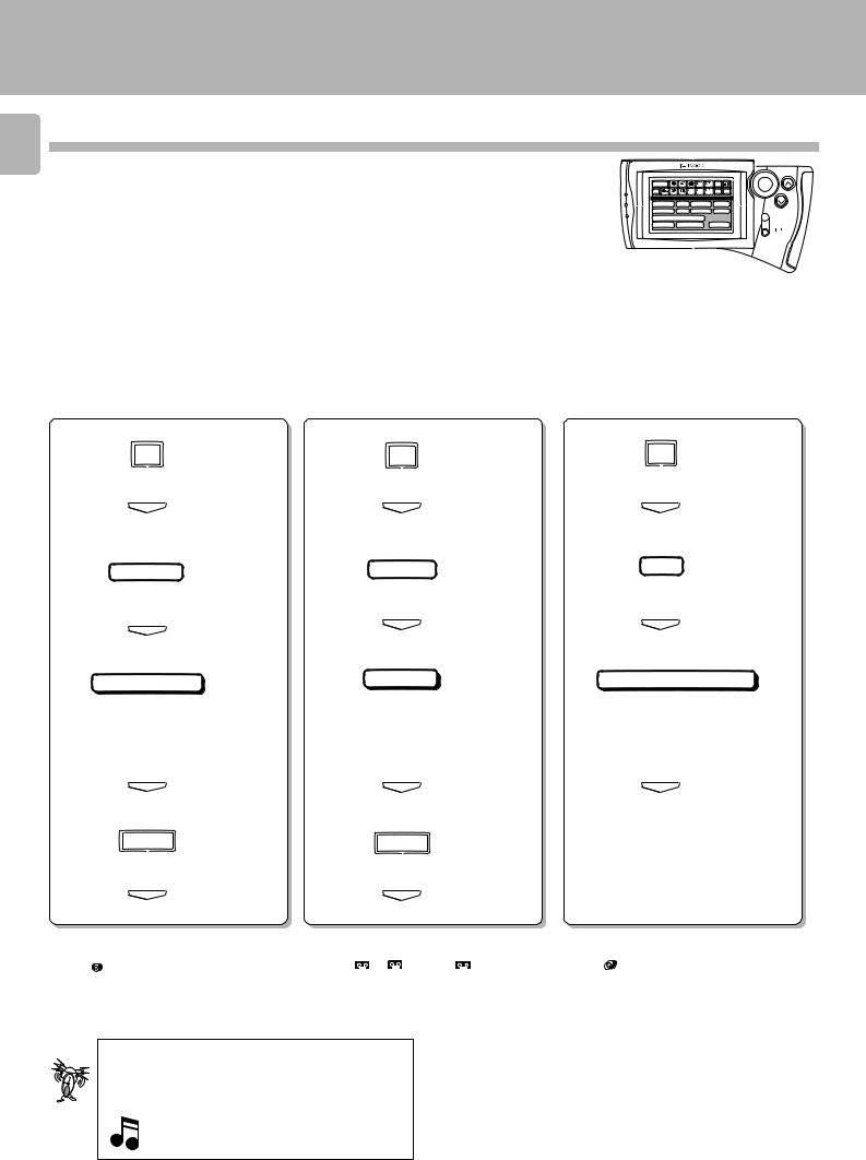
Set Up CD |
Set Up Tape 1 |
|
Set Up LD |
||
|
|
|
|
|
|
Setup of GRC according to the CD player in use
Setup of GRC according to the cassette deck in use
Setup of GRC according to the LD player in use
1 Select the ”Set Up“ icon.
Set Up
1 Select the ”Set Up“ icon.
Set Up
1 Select the ”Set Up“ icon.
Set Up
2Press the ”ENTER“ key to enter the selection.
2Press the ”ENTER“ key to enter the selection.
2Press the ”ENTER“ key to enter the selection.
ENTER |
ENTER |
ENTER |
3 Select the ”CD“ icon.
3 Select the ”Tape 1“ icon. |
3 Select the ”LD“ icon. |
C D
4Press the ”ENTER“ key to enter the selection.
ENTER
5 Select the ”Single“ icon.
Tape1
4 Press the ”ENTER“ key to enter the selection.
ENTER
5 Select the ”Dual“ icon.
L D
4 Press the ”ENTER“ key to enter the selection.
ENTER
5 Select the ”System Control“ icon.
Single |
Dual |
ÖSelect “Single”, “Dual”, “Carrousel” or “Changer” according to the connected CD player type.
6 Press the ”ENTER“ key to enter the selection.
ENTER
7 Select the ”Main Menu“ icon.
Main Menu
8 Press the ”ENTER“ key to enter the selection.
ENTER
ÖIcon CD appears at the moment the setup has completed.
ÖSelect “Dual” or “Single” according to the connected cassette deck type.
6Press the ”ENTER“ key to enter the selection.
ENTER
7 Select the ”Main Menu“ icon.
Main Menu
8Press the ”ENTER“ key to enter the selection.
ENTER
ÖIcons TapeA / TapeB or icon Tape1 appear at the moment the setup has completed.
In the operations of the GRC (Graphical Remote Control unit), proceed to each step within 10 seconds after the previous step.
The display disappears in 10 seconds.
To resume GRC display, move the Joystick key in any directions.
System Control
ÖSelect “System Control” or “IR” according to the connected LD player type.
6Press the ”ENTER“ key to enter the selection.
ENTER
ÖIcon LD appears at the moment the setup has completed.
Setup of the Graphical Remote Control (GRC) unit
C-V750 (En/T)
Setting up the GRC according to other components (Set Up) |
15 |
|
The GRC can also be used to remote control other components which are not connected through system control cords. To control another component, it is required to register the setup code corresponding to it beforehand. E
Main Menu |
Input |
ENTER |
CD Tuner LD Tape1 TapeA Source |
Return |
Cable |
Sat. |
TV |
VCR1 |
VCR2 |
TapeB |
Set Up |
Confirm |
VOLUME |
Setup
C D L D Tape1 VCR1
Sat. T V Cable VCR2
DVD/6ch Input |
MUTE |
|
Sound Speaker Reset
ON/STANDBY
Main operation menu
(The displayed icons are variable depending on the model.)
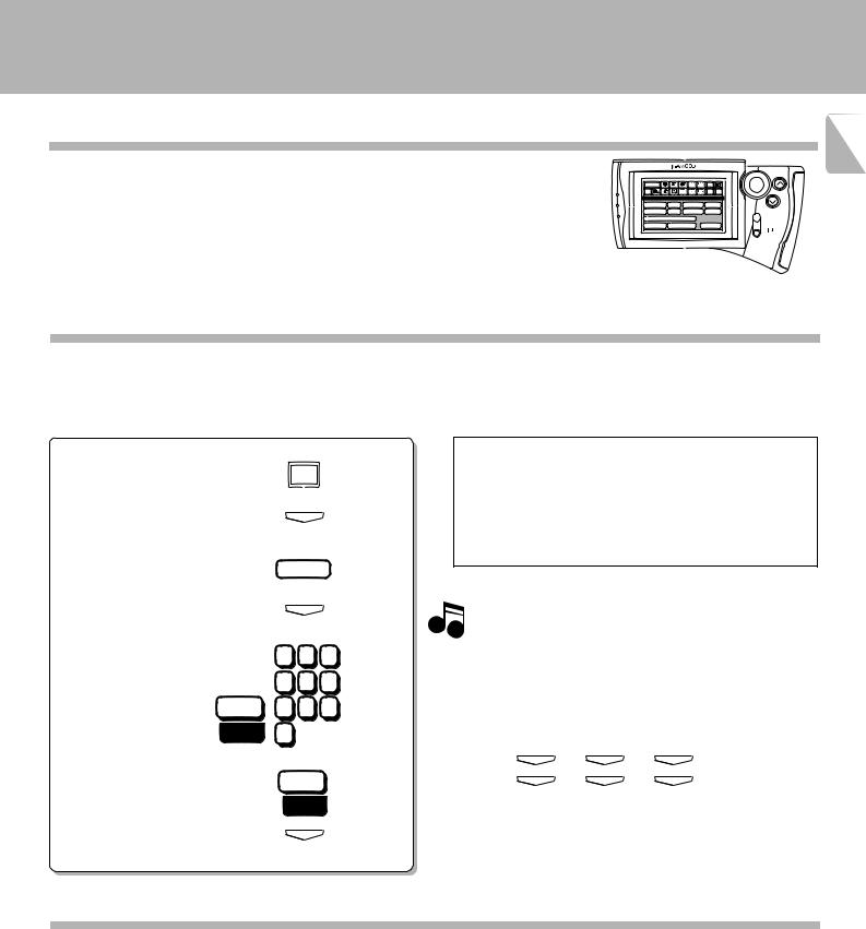
Registering setup codes for VCR 1
1 Find the setup code of the component to be registered by referring to the Setup code chart in this manual.
2Enter the setup code.
1 Select the ”Set Up“ icon. |
|
Check the operation of the component. |
|
Set Up |
1 Display the operation screen of the component to be checked. |
|
|
2 Turn on the component from the GRC and confirm the |
2 Enter the selection |
|
actual component. |
ENTER |
Ö If there is more than one setup code, input each code to see |
|
(by pressing the ”ENTER“ key). |
|
|
|
which one turns the power on. That will be the correct code for |
|
|
|
|
|
|
your component. |
3 Select the ”VCR 1“ icon. |
VCR1 |
|
|
|
|
4 Enter the selection |
ENTER |
Although each setup code is designed to work with a |
(by pressing the ”ENTER“ key). |
|
Note number of different models, certain codes may not work |
|
1 2 3 |
with some models. (Also, certain codes may only operate |
|
some of the functions available on a given model.) |
|
5 Enter the setup code. |
4 5 6 |
With some models, be sure to keep the ENTER key |
pressed for a while. |
||
Set |
7 8 9 |
Use the numeric keys as shown below. |
000 |
|
|
0 |
Entry examples: |
6 Select the ”Set“ icon.
Set
431
431 ..... |
4 |
400 ..... |
4 |
ENTER
ENTER
3
)
ENTER
ENTER
1
)
ENTER
ENTER
7Enter the selection
(by pressing the ”ENTER“ key).
ENTER
ÖWhen a code which is not shown in the setup code chart is entered, the entered code disappears automatically.
Registering setup codes of other components
The procedure of steps 1 and 2-1 to 7 of “Registering setup code for VCR 1” also allows to register the components listed below to remote control them from the GRC.
Registering setup code for VCR 2
Registering setup code for TV
Registering setup code for CABLE
Registering setup code for SATELLITE
Registering setup code for LD player (IR)
Remote control of components from the GRC
C-V750 (En/T)
16 Controlling the AV CONTROL CENTER
The operations required to remote control the AV CONTROL CENTER includes the INPUT SELECTOR selection, display mode selection, stereo selection and so on.
The following procedures show how to remote control the basic operations of the GRC.
Main Menu |
Tuner |
LD |
Tape1 |
Input |
|
ENTER |
CD |
TapeA Source |
|
|
|||
Return |
TV |
VCR1 |
VCR2 |
Set Up |
Confirm |
VOLUME |
Cable Sat. |
TapeB |
|
||||
Main Menu 1 |
|
|
|
|
||
C D |
VCR |
Tape1 / MD |
|
|||
Tuner |
AUX |
Cable / Sat. |
|
|||
L D |
DVD |
|
|
|
|
MUTE |
|
|
|
|
|
|
ON/STANDBY |
Operation examples |
|
Main operation menu |
|
(The displayed icons are variable depending |
|
|
on the model.) |
|
|
|
|
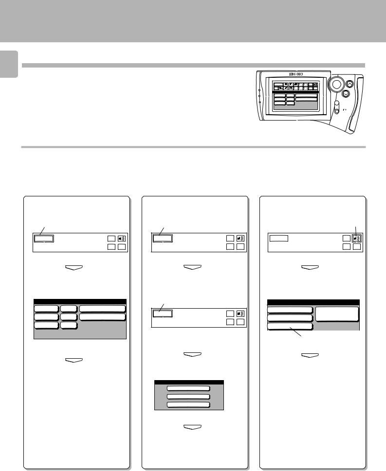
Switching the INPUT SELEC- |
Switching the display mode |
Selecting the stereo mode |
TOR (Selecting the CD input) |
of the AV CONTROL CENTER |
|
1 Select the ”Main Menu“ icon in the |
1 Select the ”Main Menu“ icon in the |
1 Select the ”Sound“ icon in the fixed |
||||
fixed segment screen by operating |
fixed segment screen by operating |
segment screen by operating the joy- |
||||
the joystick. |
|
the joystick. |
|
stick. |
|
|
1 |
|
1 |
|
|
1 |
|
Main Menu |
Input |
Main Menu |
Input |
Main Menu |
Input |
|
Source |
Source |
Source |
||||
|
|
|
||||
|
Set Up Confirm |
|
Set Up Confirm |
|
Set Up Confirm |
|
2 Press the ”ENTER“ key to enter the
selection.
ENTER
3Select the ”CD“ icon with the joystick.
Main Menu 1
C D VCR Tape1 / MD
Tuner AUX Cable / Sat.
L D DVD
4Press the ”ENTER“ key to enter the selection.
ENTER
5 The input source is switched to ”CD“.
2 Press the ”ENTER“ key to enter the
selection.
ENTER
3 Select the ”Main Menu“ icon again.
3
Main Menu |
Input |
|
Source |
||
|
||
|
Set Up Confirm |
4 Press the ”ENTER“ key to enter the
selection.
ENTER
5 Select the ”Display“ icon.
Main Menu 2
Tape2 Monitor
Sleep
Display
2 Press the ”ENTER“ key to enter the
selection.
ENTER
3Select the ”STEREO“ icon with the joystick.
Sound
PRO LOGIC |
Source |
3 STEREO |
Direct |
STEREO |
|
3
4 Press the ”ENTER“ key to enter the selection.
ENTER
ÖIt is also possible to select the Pro Logic, 3 STEREO or Source Direct icon in step
3.
ÖOther input than CD can be selected in step 3.
6 Press the ”ENTER“ key to enter the selection.
ENTER
7Each press of the ”ENTER“ key switches the display mode.
ÖIt is also possible to select the Tape 2 Monitor or Sleep icon in step 5.
Remote control of components from the GRC
C-V750 (En/T)
Controlling the components connected through system control cords |
17 |
|
When a CD player, cassette deck and/or LD player are connected with the AV CONTROL CENTER through system control cords, their system control operations are possible from the GRC.
Preparations |
Ö System control connection |
8 |
|
Ö Model Type Setup |
# |
|
Ö Setup of source components $ |
|
Main Menu |
Tuner |
LD |
Tape1 |
Input |
|
ENTER |
CD |
TapeA Source |
|
|
|||
Return |
TV |
VCR1 |
VCR2 |
Set Up |
Confirm |
VOLUME |
Cable Sat. |
TapeB |
|
||||
Main Menu 1 |
|
|
|
|
||
C D |
VCR |
Tape1 / MD |
|
|||
Tuner |
AUX |
Cable / Sat. |
|
|||
L D |
DVD |
|
|
|
|
MUTE |
|
|
|
|
|
|
ON/STANDBY |
|
|
Main operation menu |
|
|
(The displayed icons are variable depending |
|
|
on the model.) |
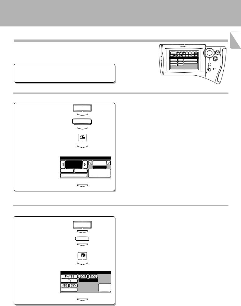
Operating the tuner |
|
|
1 Select the ”Tuner“ input. |
Main Menu |
Ö After selecting the icon, press the ”ENTER“ key to enter the selection. |
|
|
|
|
ENTER |
|
|
Tuner |
|
|
ENTER |
|
2 Display the tuner operation |
|
|
menu. |
Tuner |
|
|
|
|
|
ENTER |
|
3 Select the icon to be operated. |
|
Ö Any of the keys which can control the tuner can be selected. |
Tuner
100.00P.Call
fm |
MHz |
01ch |
Auto |
Band |
Memory / |
RDS |
10key Pad |
|
4 Enter the selection
(by pressing the ”ENTER“
key). |
ENTER |
|
Operating the CD player
1 Select the ”CD“ input.
Main Menu
ENTER
|
|
C D |
|
|
ENTER |
2 Display the CD operation menu. |
|
|
|
|
CD |
|
|
ENTER |
3 Select the icon to be operated. |
Ö Any of the CD player operation keys can be selected. |
|
|
CD |
Ö The menu display shown on the left is an example which appears with |
|
|
a single CD player. |
|
|
Track 01 |
|
|
10key |
4 Enter the selection |
Mode |
Pad |
|
Ö For the operation of the CD player, also read the instruction manual of |
|
(by pressing the ”ENTER“ |
|
the CD player. |
key). |
|
ENTER |
Remote control of components from the GRC
C-V750 (En/T)
18 |
Main Menu |
Tuner |
LD |
Tape1 |
TapeA |
Input |
ENTER |
CD |
Source |
|
|||||
Return Cable Sat. |
TV |
VCR1 |
VCR2 |
TapeB |
Set Up Confirm |
VOLUME |
|
|
Main Menu 1 |
|
|
|
|
||
|
C D |
VCR |
Tape1 / MD |
|
|||
|
Tuner |
AUX |
Cable / Sat. |
|
|||
|
L D |
DVD |
|
|
|
|
MUTE |
|
|
|
|
|
|
|
ON/STANDBY |
|
Main operation menu |
|
|
|
|||
|
(The displayed icons are variable depending |
||||||
|
on the model.) |
|
|
|
|
|
|
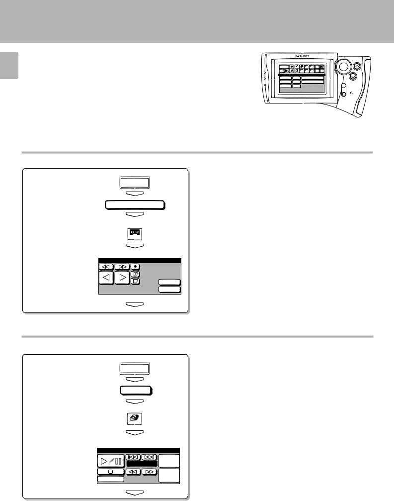
Operating the cassette deck
1 Select the ”Tape 1“ input.
Main Menu
ENTER
Tape1 / MD
ENTER
2Display the cassette deck operation menu.
TapeB
ÖThe procedure on the left is an example assuming that “Dual” has been selected in the ”Setup“ operation.
ÖIn case “Single” was selected in the Setup operation, the ”Tape 1“ icon is displayed.
|
ENTER |
3 Select the icon to be operated. |
Ö Any of the cassette deck operation keys can be selected. |
Tape B
4Enter the selection
(by pressing the ”ENTER“ key).
O.T.E.
CCRS
ENTER
Ö For the operation of the cassette deck, also read the instruction manual of the cassette deck.
Operating the LD player
1 Select the ”LD“ input.
Main Menu
ENTER
L D
ENTER
2Display the LD player operation menu.
3Select the icon to be operated.
4Enter the selection
(by pressing the
”ENTER“ key).
LD
ENTER
LD
Video
Track 01 CD
10key
Mode 
 Pad
Pad
ÖAny of the LD player operation keys can be selected.
ÖThe procedure on the left is an example assuming that “System Control” has been selected in the ”Setup“ operation.
ÖFor the operation of the LD player, also read the instruction manual of the LD player.
ENTER
 Loading...