


DDX512
DDX5032
MONITOR WITH DVD RECEIVER
INSTALLATION MANUAL
MONITEUR AVEC RÉCEPTEUR DVD
MANUEL D’INSTALLATION
MONITOR CON RECEPTOR DVD
MANUAL DE INSTALACIÓN
© B54-4618-00/00 (KW/RW)
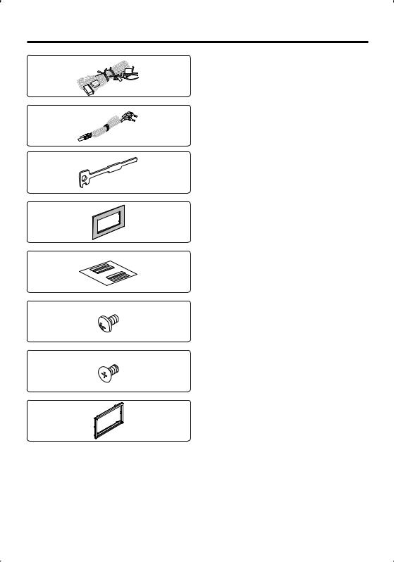
Accessories
1
..........1
2
..........1
3
..........2
4
..........1
5
..........1
6
..........6
7
..........6
8
..........1
2 | DDX512/DDX5032

Installation Procedure
1.To prevent a short circuit, remove the key from the ignition and disconnect the - battery.
2.Make the proper input and output wire connections for each unit.
3.Connect the speaker wires of the wiring harness.
4.Connect the wiring harness wires in the following order: ground, battery, ignition.
5.Connect the wiring harness connector to the unit.
6.Install the unit in your car.
7.Reconnect the - battery.
8.Press the reset button.
2WARNING
•If you connect the ignition wire (red) and the battery wire (yellow) to the car chassis (ground), you may cause a short circuit, that in turn may start a fire. Always connect those wires to the power source running through the fuse box.
¤
•Mounting and wiring this product requires skills and experience. For safety’s sake, leave the mounting and wiring work to professionals.
•Make sure to ground the unit to a negative 12V DC power supply.
•Do not install the unit in a spot exposed to direct sunlight or excessive heat or humidity. Also avoid places with too much dust or the possibility of water splashing.
•Do not use your own screws. Use only the screws provided. If you use the wrong screws, you could damage the unit.
•If the power is not turned ON (“PROTECT” is displayed), the speaker wire may have a short-circuit or touched the chassis of the vehicle and the protection function may have been activated. Therefore, the speaker wire should be checked.
•If your car’s ignition does not have an ACC position, connect the ignition wires to a power source that can be turned on and off with the ignition key. If you connect the ignition wire to a power source with a constant voltage supply, as with battery wires, the battery may die.
•If the console has a lid, make sure to install the unit so that the faceplate will not hit the lid when closing and opening.
•If the fuse blows, first make sure the wires aren’t touching to cause a short circuit, then replace the old fuse with one with the same rating.
•Insulate unconnected wires with vinyl tape or other similar material. To prevent a short circuit, do not remove the caps on the ends of the unconnected wires or the terminals.
•Connect the speaker wires correctly to the terminals to which they correspond. The unit may be damaged or fail to work if you share the - wires or ground them to any metal part in the car.
•When only two speakers are being connected to the system, connect the connectors either to both the front output terminals or to both the rear output terminals (do not mix front and rear). For example, if you connect the + connector of the left speaker to a front output terminal, do not connect the - connector to a rear output terminal.
•After the unit is installed, check whether the brake lamps, blinkers, wipers, etc. on the car are working properly.
•Mount the unit so that the mounting angle is 30° or less.
•This unit has the cooling fan (page 5) to decrease the internal temperature. Do not mount the unit in a place where the cooling fan of the unit are blocked. Blocking these openings will inhibit the cooling of the internal temperature and result in malfunction.
•Do not press hard on the panel surface when installing the unit to the vehicle. Otherwise scars, damage, or failure may result.
English | 3
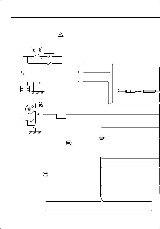
Connection
Ignition key switch
If you connect the ignition wire (red) and the battery wire (yellow) to the car chassis (ground), you may cause a short circuit, that in turn may start a fire. Always connect those wires to the power source running through the fuse box.
ACC A
Ignition wire (Red)
B A 
|
|
|
|
|
|
|
|
|
|
|
|
|
|
Car fuse box |
B |
Battery wire (Yellow) |
|
|
|
|
|
Car fuse box |
|
||||||||||
|
|
|
|
|
(Main fuse) |
|
Ground wire (Black) - |
|||||||||
|
|
|
|
|
|
|
|
|
|
|
|
|
|
|
C |
(To car chassis) |
|
|
|
|
|
|
|
|
|
|
|
|
|
|
C |
Antenna Cord |
|
|
|
|
|
|
|
|
|
|
|
|
|
|
|
|
||
|
|
|
|
|
|
|
|
|
|
|
||||||
|
|
|
|
|
|
|
|
|
|
|
||||||
+–
Battery
Connect to the vehicle's parking brake detection switch harness.
Parking sensor wire (Light Green)
PRK SW |
For the sake of safety, be sure to connect the parking sensor. |
|
Connect to vehicle's reverse lamp harness when using the optional rear view camera.
To steering remote
Reveres sensor wire (Purple/White)
Steering remote control input (Light Blue/Yellow)
To use the steering wheel remote control feature, you need to an exclusive remote adapter (not supplied) matches your car is required. When this terminal is not in use, leave its cap on.
To car light control switch
Connect to the terminal that is grounded when either the telephone rings or during conversation.
To connect the Kenwood navigation system, consult your navigation manual.
Depending on what antenna you are using, connect either to the control terminal of the motor antenna, or to the power terminal for the booster amplifier of the film-type antenna.
When using the optional power amplifier, connect to its power control terminal.
Dimmer control wire (Orange/White)
Mute wire (Brown)
Motor antenna control wire (Blue)
Power control wire (Blue/White)
 If no connections are made, do not let the cable come out from the tab.
4 | DDX512/DDX5032

Cooling fan
FM/AM antenna input
|
Wiring harness |
FUSE ( 15A ) |
(Accessory 1) |
|
REVERSE
REMO.CONT
ILLUMI
MUTE
ANT. CONT
REAR R REAR L FRONT R FRONT L

White/Black
White + |
To front left speaker |
|
|
Gray/Black |
|
+ |
To front right speaker |
|
|
Gray |
|
Green/Black |
|
+ |
To rear left speaker |
|
|
Green |
|
Purple/Black |
|
Purple + |
To rear right speaker |
|
P CONT
English | 5
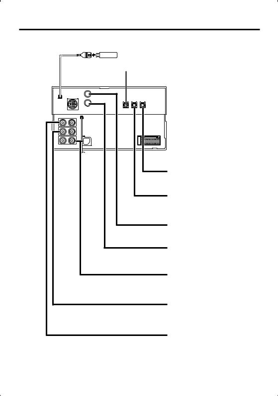
System Connection
USB device
USB terminal (commercially available)
Do not connect.
|
■ |
|
■ |
|
■ |
|
■ |
|
■ |
|
■ |
|
■ |
6 | |
DDX512/DDX5032 |
Audio Input
Resistance-free stereo type mini plug (3.5φ)
Visual Input
Resistance-free mini plug (3.5φ)
Rear View Camera Input
• Visual input (Yellow)
Audio/Visual Output
• Visual output (Yellow)
Front Preout
•Audio left output (White)
•Audio right output (Red)
Rear Preout/ Subwoofer Preout
•Audio left output (White)
•Audio right output (Red)
Audio/Visual Output
•Audio left output (White)
•Audio right output (Red)
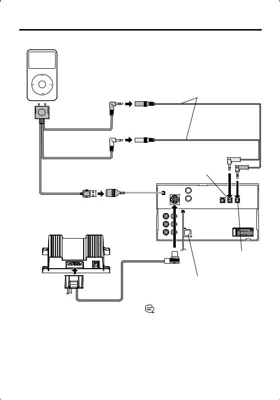
Optional Accessory Connection
iPod
(commercially available)
Accessory 2
 KCA-iP300V
  (Optional Accessory)
Audio Output (Black)
Visual Output (Yellow)
Visual Input (Yellow)
|
|
|
|
|
|
USB terminal |
USB terminal |
||||
Navigation System
(Optional Accessory)
Audio Input |
(Black) |
To SIRIUS Satellite Radio tuner/
XM Satellite Radio tuner/ HD Radio tuner/ KCA-BT200
(Optional Accessory)
Connection cable |
Conversion adapter (Optional Accessory) may be |
(Included in the Navigation System) |
necessary for connection of Optional Accessory. |
|
Contact your Kenwood dealer for details. |
English | 7
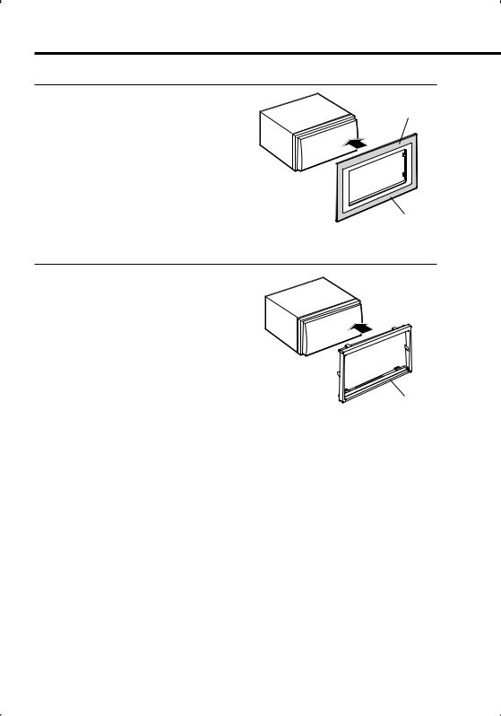
Installing the Escutcheon
For General Motors
1.Cut out accessory 4 to meet the shape of the opening of the center console.
2.Attach accessory 4 to the unit.
For Volkswagen
1. Attach accessory 8 to the unit.
Cut out to meet the shape of the opening in the vehicle.
Accessory 4
Accessory 8
8 | DDX512/DDX5032
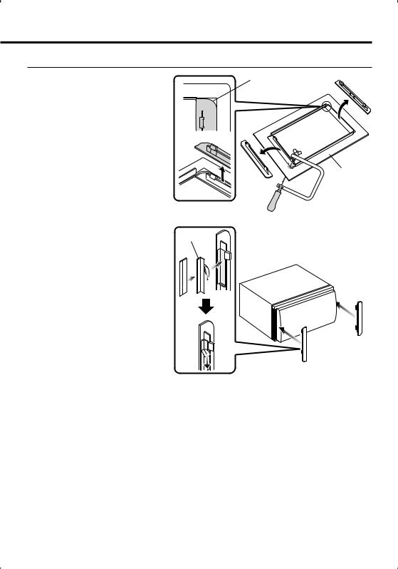
For Toyota/Scion
1. Cut out accessory 4 as illustrated. |
Cutting line |
|
Accessory 4
2.Fold double-sided adhesive (accessory 5) along the slit and attach it to
accessory 4 cut-out against the |
Accessory 5 |
|
|
center rib as illustrated. Use 2 pieces |
|
of accessory 5 for 1 accessory 4 cut- |
|
out. |
|
3. Attach accessory 4 cut-out to the unit.
English | 9
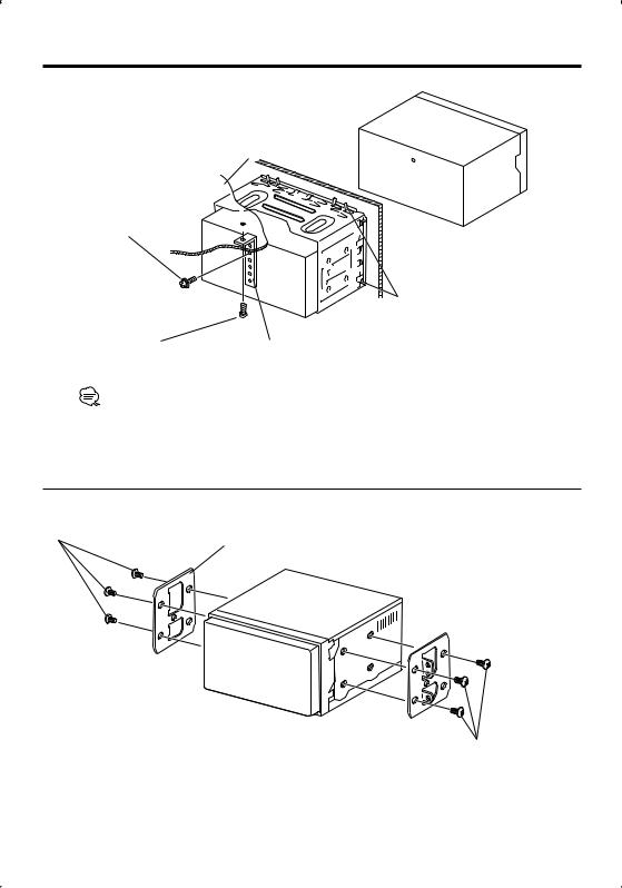
Installation for Monitor/Player Unit
Firewall or metal support
Screw (M4X8) (commercially available)
Bend the tabs of the mounting sleeve with a screwdriver or similar utensil and attach it in place.
Self-tapping screw |
Metal mounting strap |
(commercially available) |
(commercially available) |
Make sure that the unit is installed securely in place. If the unit is unstable, it may malfunction (eg, the sound may skip).
Installation on Toyota, Nissan or Mitsubishi Car using Brackets
Accessory 6 (M5x6mm)
or Accessory 7 (M5x7mm)
Car Bracket
Accessory 6 (M5x6mm) or Accessory 7 (M5x7mm)
10 | DDX512/DDX5032
 Loading...