


 Loading...
SERVICE MANUAL
CASSETTE RECEIVER
KS-F185,KS-F185S,KS-F185G
|
KS - F185 |
|
|
|
Area suffix |
UH |
---------------------- Thailand |
UN --------------------- |
Indonesia |
U -------------------- |
Other Areas |
|
|
|
KS - F185S |
|
|
|
Area suffix |
UN |
--------------------- Indonesia |
|
|
|
|
|
KS - F185G |
|
|
|
Area suffix |
UN --------------------- |
Indonesia |
|
|
TABLE OF CONTENTS
1 PRECAUTION. . . . . . . . . . . . . . . . . . . . . . . . . . . . . . . . . . . . . . . . . . . . . . . . . . . . . . . . . . . . . . . . . . . . . . . . . 1-3 2 SPECIFIC SERVICE INSTRUCTIONS . . . . . . . . . . . . . . . . . . . . . . . . . . . . . . . . . . . . . . . . . . . . . . . . . . . . . . 1-4 3 DISASSEMBLY . . . . . . . . . . . . . . . . . . . . . . . . . . . . . . . . . . . . . . . . . . . . . . . . . . . . . . . . . . . . . . . . . . . . . . . 1-5 4 ADJUSTMENT . . . . . . . . . . . . . . . . . . . . . . . . . . . . . . . . . . . . . . . . . . . . . . . . . . . . . . . . . . . . . . . . . . . . . . . 1-13 5 TROUBLESHOOTING . . . . . . . . . . . . . . . . . . . . . . . . . . . . . . . . . . . . . . . . . . . . . . . . . . . . . . . . . . . . . . . . . 1-17
COPYRIGHT © 2005 Victor Company of Japan, Limited
No.MA094B
2005/3
|
SPECIFICATION |
|
|
||
|
|
|
|||
|
AUDIO AMPLIFIER SECTION |
|
|||
|
|
|
|
|
|
Maximum Power Output |
Front |
|
45 W per channel |
|
|
|
|
|
|
|
|
|
Rear |
|
45 W per channel |
|
|
|
|
|
|
||
Continuous Power Output |
Front |
|
17 W per channel into 4 Ω , 40 Hz to 20 000 Hz at no more than |
||
(RMS) |
|
|
0.8% total harmonic distortion. |
||
|
Rear |
|
17 W per channel into 4 Ω , 40 Hz to 20 000 Hz at no more than |
||
|
|
|
0.8% total harmonic distortion. |
||
|
|
|
|
||
Load Impedance |
|
|
4 Ω (4 Ω to 8 Ω allowance) |
||
|
|
|
|
|
|
Tone Control Range |
Bass |
|
±10 dB at 100 Hz |
|
|
|
|
|
|
|
|
|
Treble |
|
±10 dB at 10 kHz |
|
|
|
|
|
|
|
|
Frequency Response |
|
|
40 Hz to 20 000 Hz |
|
|
|
|
|
|
|
|
Signal-to-Noise Ratio |
|
|
70 dB |
|
|
|
|
|
|
||
Line-Out Level/Impedance |
|
|
1.0 V/20 kΩ load (250 nWb/m) |
||
|
|
|
|
|
|
|
|
TUNER SECTION |
|
|
|
|
|
|
|
||
Frequency Range |
FM |
|
87.5 MHz to 108.0 MHz |
||
|
|
|
|
||
|
AM |
|
531 kHz to 1 602 kHz |
||
|
|
|
|
||
[FM Tuner] |
Usable Sensitivity |
|
11.3 dBf (1.0 µV/75 Ω ) |
||
|
|
|
|
||
|
50 dB Quieting Sensitivity |
|
16.3 dBf (1.8 µV/75 Ω ) |
||
|
|
|
|
|
|
|
Alternate Channel Selectivity (400 kHz) |
65 dB |
|
|
|
|
|
|
|
|
|
|
Frequency Response |
|
40 Hz to 15 000 Hz |
|
|
|
|
|
|
|
|
|
Stereo Separation |
|
35 dB |
|
|
|
|
|
|
|
|
|
Capture Ratio |
|
2.0 dB |
|
|
|
|
|
|
|
|
[AM Tuner] |
Sensitivity |
|
20 µV |
|
|
|
|
|
|
|
|
|
Selectivity |
|
35 dB |
|
|
|
|
|
|
||
|
CASSETTE DECK SECTION |
|
|||
|
|
|
|
|
|
Wow & Flutter |
|
|
0.15% (WRMS) |
|
|
|
|
|
|
|
|
Fast-Wind Time |
|
|
190 sec. (C-60) |
|
|
|
|
|
|
||
Frequency Response |
|
|
50 Hz to 14 000 Hz (Normal tape) |
||
|
|
|
|
|
|
Signal-to-Noise Ratio |
|
|
52 dB |
|
|
|
|
|
|
|
|
Stereo Separation |
|
|
40 dB |
|
|
|
|
|
|
|
|
|
|
GENERAL |
|
|
|
|
|
|
|
||
Power Requirement |
Operating Voltage |
|
DC 14.4 V (11 V to 16 V allowance) |
||
|
|
|
|
|
|
Grounding System |
|
|
Negative ground |
|
|
|
|
|
|
||
Allowable Operating Temperature |
|
0ºC to +40ºC |
|
||
|
|
|
|
|
|
Dimensions (W × H × D) |
Installation Size (approx.) |
|
182 mm × |
52 mm × |
150 mm |
|
|
|
|
|
|
|
Panel Size (approx.) |
|
188 mm × |
58 mm × |
11 mm |
|
|
|
|
||
Mass (approx.) |
|
|
1.3 kg (excluding accessories) |
||
|
|
|
|
||
Design and specifications are subject to change without notice. |
|
|
|||
1-2 (No.MA094B)

SECTION 1
PRECAUTION
1.1Safety Precautions
!


 Burrs formed during molding may be left over on some parts of the chassis. Therefore,
pay attention to such burrs in the case of preforming repair of this system.
(No.MA094B)1-3

SECTION 2
SPECIFIC SERVICE INSTRUCTIONS
2.1HOW TO IDENTIFY MODELS
2.1.1 NAME PLATE
Discernment sign
1-4 (No.MA094B)

SECTION 3
DISASSEMBLY
3.1Main body
3.1.1Removing the front panel assembly (See Fig.1)
(1)Push the detach button and remove the front panel assembly.
3.1.2 Removing the bottom cover (See Fig.2)
•Prior to performing the following procedures, remove the front panel assembly.
(1)Turn the body upside down.
(2)Insert a screwdriver under the joints to release the two joints a on the left side, the two joints b on the right side and the joint c on the back of the body, then remove the bottom cover from the body.
CAUTION:
When releasing the joints using a screwdriver, do not damage the board.
3.1.3 Removing the front chassis assembly (See Fig.3)
•Prior to performing the following procedures, remove the front panel assembly and bottom cover.
(1)Remove the two screws A on each side of the body.
(2)Release the two joints d and the two joints e on the sides, then remove the front chassis assembly toward the front.
Front panel assembly
Detach button
Fig.1
Bottom cover
 Joint b
Joint a
 Joint b
Joint a 
Joint c
Fig.2
Joint d |
Joint e |
A
Joint d Joint e
Front chassis assembly
Fig.3
(No.MA094B)1-5
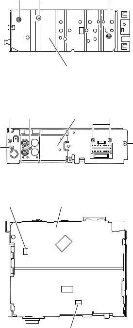
3.1.4 Removing the heat sink (See Fig.4)
•Prior to performing the following procedure, remove the front panel assembly.
(1)Remove the screw B and two screws C attaching the heat sink on the left side of the body, and remove the heat sink.
3.1.5Removing the rear panel (See Fig.5)
•Prior to performing the following procedure, remove the front panel assembly and bottom cover.
(1)Remove the two screws D , screw E and three screws F attaching the rear panel on the back of the body.
3.1.6Removing the main board (See Fig.6)
•Prior to performing the following procedures, remove the front panel assembly, bottom cover, front chassis assembly, heat sink and rear panel.
(1)Remove the two screws G attaching the main board on the top chassis.
(2)Disconnect the two connectors (CN901 and CN721) on the main board from the cassette mechanism assembly.
C B C
Heat sink
Fig.4
D F |
Rear panel F |
E |
D |
|
|
|
Fig.5 |
CN721 Main board
G

 G
G
CN901
Fig.6
1-6 (No.MA094B)
Loading...