

Page 1

An Oshkosh Corporation Company
Service Manual
Models
L2906H, 2906H,
3507H, 619A,
723A
Agrovector
29.6LP, 29.6, 35.7
31200568
Revised
March 7, 2011
Page 2

Page 3

EFFECTIV IT Y PAGE
May 30, 2009 - A - Original Issue Of Manual
March 7, 2011 - B - Added Models 29.6LP, 29.6 & 35.7. Updated all Loctite
and pages 1-3 & 9-10 thru 9-100.
®
242TM with Loctite® 243TM. Revised covers
L2906H, 2906H, 3507H, 619A, 723A, 29.6LP, 29.6, 35.7
a
Page 4

EFFECTIV IT Y PAGE
b
L2906H, 2906H, 3507H, 619A, 723A, 29.6LP, 29.6, 35.7
Page 5

SECTION CONTENTS
Section Subject Page
Section 1
Safety Practices . . . . . . . . . . . . . . . . . . . . . . . . . . . . . . . . . . . . . . . . . . . . . . . . . . . . . . . 1-1
1.1 Introduction . . . . . . . . . . . . . . . . . . . . . . . . . . . . . . . . . . . . . . . . . . . . . . . . . . . . . . . . . . 1-2
1.2 Disclaimer . . . . . . . . . . . . . . . . . . . . . . . . . . . . . . . . . . . . . . . . . . . . . . . . . . . . . . . . . . . 1-2
1.3 Operation & Safety Manual . . . . . . . . . . . . . . . . . . . . . . . . . . . . . . . . . . . . . . . . . . . . . . 1-2
1.4 Do Not Operate Tags . . . . . . . . . . . . . . . . . . . . . . . . . . . . . . . . . . . . . . . . . . . . . . . . . . . 1-2
1.5 Safety Information . . . . . . . . . . . . . . . . . . . . . . . . . . . . . . . . . . . . . . . . . . . . . . . . . . . . . 1-2
1.6 Safety Instructions . . . . . . . . . . . . . . . . . . . . . . . . . . . . . . . . . . . . . . . . . . . . . . . . . . . . . 1-3
1.7 Safety Decals. . . . . . . . . . . . . . . . . . . . . . . . . . . . . . . . . . . . . . . . . . . . . . . . . . . . . . . . .1-4
Section 2
General Information and Specifications . . . . . . . . . . . . . . . . . . . . . . . . . . . . . . . . . . . . 2-1
2.1 Replacement Parts and Warranty Information. . . . . . . . . . . . . . . . . . . . . . . . . . . . . . . . 2-2
2.2 Torques . . . . . . . . . . . . . . . . . . . . . . . . . . . . . . . . . . . . . . . . . . . . . . . . . . . . . . . . . . . . . 2-3
2.3 Specifications. . . . . . . . . . . . . . . . . . . . . . . . . . . . . . . . . . . . . . . . . . . . . . . . . . . . . . . . . 2-11
2.4 Fluids, Lubricants and Capacities . . . . . . . . . . . . . . . . . . . . . . . . . . . . . . . . . . . . . . . . . 2-13
2.5 Maintenance Schedules. . . . . . . . . . . . . . . . . . . . . . . . . . . . . . . . . . . . . . . . . . . . . . . . . 2-15
2.6 Lubrication Schedule . . . . . . . . . . . . . . . . . . . . . . . . . . . . . . . . . . . . . . . . . . . . . . . . . . . 2-16
Section 3
Boom . . . . . . . . . . . . . . . . . . . . . . . . . . . . . . . . . . . . . . . . . . . . . . . . . . . . . . . . . . . 3-1
3.1 Boom System Component Terminology. . . . . . . . . . . . . . . . . . . . . . . . . . . . . . . . . . . . . 3-2
3.2 Safety Information . . . . . . . . . . . . . . . . . . . . . . . . . . . . . . . . . . . . . . . . . . . . . . . . . . . . . 3-3
3.3 Boom System - Two Section Boom . . . . . . . . . . . . . . . . . . . . . . . . . . . . . . . . . . . . . . . . 3-3
3.4 Boom Assembly Maintenance . . . . . . . . . . . . . . . . . . . . . . . . . . . . . . . . . . . . . . . . . . . . 3-3
3.5 Boom Wear Pads. . . . . . . . . . . . . . . . . . . . . . . . . . . . . . . . . . . . . . . . . . . . . . . . . . . . . . 3-8
3.6 Quick Attach Assembly . . . . . . . . . . . . . . . . . . . . . . . . . . . . . . . . . . . . . . . . . . . . . . . . . 3-9
3.7 Forks . . . . . . . . . . . . . . . . . . . . . . . . . . . . . . . . . . . . . . . . . . . . . . . . . . . . . . . . . . . . . . . 3-10
3.8 Boom Prop (If Equipped) . . . . . . . . . . . . . . . . . . . . . . . . . . . . . . . . . . . . . . . . . . . . . . . . 3-10
3.9 Emergency Boom Lowering Procedure. . . . . . . . . . . . . . . . . . . . . . . . . . . . . . . . . . . . . 3-11
3.10 Troubleshooting . . . . . . . . . . . . . . . . . . . . . . . . . . . . . . . . . . . . . . . . . . . . . . . . . . . . . . .3-13
Section 4
Cab and Covers . . . . . . . . . . . . . . . . . . . . . . . . . . . . . . . . . . . . . . . . . . . . . . . . . . . . . . . . 4-1
4.1 Operator Cab and Covers Component Terminology . . . . . . . . . . . . . . . . . . . . . . . . . . . 4-2
4.2 Safety Information . . . . . . . . . . . . . . . . . . . . . . . . . . . . . . . . . . . . . . . . . . . . . . . . . . . . . 4-3
4.3 Operator Cab . . . . . . . . . . . . . . . . . . . . . . . . . . . . . . . . . . . . . . . . . . . . . . . . . . . . . . . . .4-3
4.4 Cab Components. . . . . . . . . . . . . . . . . . . . . . . . . . . . . . . . . . . . . . . . . . . . . . . . . . . . . . 4-3
4.5 Cab Removal . . . . . . . . . . . . . . . . . . . . . . . . . . . . . . . . . . . . . . . . . . . . . . . . . . . . . . . . . 4-8
4.6 Cab Installation . . . . . . . . . . . . . . . . . . . . . . . . . . . . . . . . . . . . . . . . . . . . . . . . . . . . . . .4-9
L2906H, L2906H, 2906H, 3507H, 619A, 723A, 29.6LP, 29.6, 35.7
i
Page 6

Section Subject Page
Section 5
Axles, Drive Shafts, Wheels and Tires . . . . . . . . . . . . . . . . . . . . . . . . . . . . . . . . . . . . . . 5-1
5.1 Axle, Drive Shaft and Wheel Component Terminology . . . . . . . . . . . . . . . . . . . . . . . . . 5-2
5.2 Safety Information . . . . . . . . . . . . . . . . . . . . . . . . . . . . . . . . . . . . . . . . . . . . . . . . . . . . . 5-3
5.3 General Information . . . . . . . . . . . . . . . . . . . . . . . . . . . . . . . . . . . . . . . . . . . . . . . . . . . . 5-3
5.4 Axle Assemblies. . . . . . . . . . . . . . . . . . . . . . . . . . . . . . . . . . . . . . . . . . . . . . . . . . . . . . . 5-3
5.5 Drive Shafts . . . . . . . . . . . . . . . . . . . . . . . . . . . . . . . . . . . . . . . . . . . . . . . . . . . . . . . . . . 5-9
5.6 Wheels and Tires . . . . . . . . . . . . . . . . . . . . . . . . . . . . . . . . . . . . . . . . . . . . . . . . . . . . . . 5-10
5.7 Steering Angle Adjustment. . . . . . . . . . . . . . . . . . . . . . . . . . . . . . . . . . . . . . . . . . . . . . . 5-11
5.8 Brakes . . . . . . . . . . . . . . . . . . . . . . . . . . . . . . . . . . . . . . . . . . . . . . . . . . . . . . . . . . . . . . 5-11
Section 6
Transmission . . . . . . . . . . . . . . . . . . . . . . . . . . . . . . . . . . . . . . . . . . . . . . . . . . . . . . . . . .6-1
6.1 Transmission Assembly Component Terminology . . . . . . . . . . . . . . . . . . . . . . . . . . . . . 6-2
6.2 Safety Information . . . . . . . . . . . . . . . . . . . . . . . . . . . . . . . . . . . . . . . . . . . . . . . . . . . . . 6-3
6.3 Transmission Description. . . . . . . . . . . . . . . . . . . . . . . . . . . . . . . . . . . . . . . . . . . . . . . . 6-3
6.4 Transmission Specifications. . . . . . . . . . . . . . . . . . . . . . . . . . . . . . . . . . . . . . . . . . . . . . 6-3
6.5 Transmission Replacement . . . . . . . . . . . . . . . . . . . . . . . . . . . . . . . . . . . . . . . . . . . . . . 6-3
6.6 Transmission Filter Replacement. . . . . . . . . . . . . . . . . . . . . . . . . . . . . . . . . . . . . . . . . . 6-5
6.7 Towing a Disabled Machine . . . . . . . . . . . . . . . . . . . . . . . . . . . . . . . . . . . . . . . . . . . . . . 6-6
Section 7
Engine: Deutz TCD 2012 . . . . . . . . . . . . . . . . . . . . . . . . . . . . . . . . . . . . . . . . . . . . . . . . . 7-1
7.1 Introduction . . . . . . . . . . . . . . . . . . . . . . . . . . . . . . . . . . . . . . . . . . . . . . . . . . . . . . . . . . 7-2
7.2 Safety Information . . . . . . . . . . . . . . . . . . . . . . . . . . . . . . . . . . . . . . . . . . . . . . . . . . . . . 7-4
7.3 Engine Serial Number . . . . . . . . . . . . . . . . . . . . . . . . . . . . . . . . . . . . . . . . . . . . . . . . . . 7-4
7.4 Specifications and Maintenance Information . . . . . . . . . . . . . . . . . . . . . . . . . . . . . . . . . 7-4
7.5 Engine Cooling System . . . . . . . . . . . . . . . . . . . . . . . . . . . . . . . . . . . . . . . . . . . . . . . . . 7-4
7.6 Engine Electrical System . . . . . . . . . . . . . . . . . . . . . . . . . . . . . . . . . . . . . . . . . . . . . . . . 7-5
7.7 Fuel System . . . . . . . . . . . . . . . . . . . . . . . . . . . . . . . . . . . . . . . . . . . . . . . . . . . . . . . . . .7-5
7.8 Engine Exhaust System. . . . . . . . . . . . . . . . . . . . . . . . . . . . . . . . . . . . . . . . . . . . . . . . . 7-7
7.9 Air Cleaner Assembly. . . . . . . . . . . . . . . . . . . . . . . . . . . . . . . . . . . . . . . . . . . . . . . . . . . 7-8
7.10 Engine Replacement . . . . . . . . . . . . . . . . . . . . . . . . . . . . . . . . . . . . . . . . . . . . . . . . . . . 7-8
7.11 Engine Coupler . . . . . . . . . . . . . . . . . . . . . . . . . . . . . . . . . . . . . . . . . . . . . . . . . . . . . . .7-10
7.12 Troubleshooting . . . . . . . . . . . . . . . . . . . . . . . . . . . . . . . . . . . . . . . . . . . . . . . . . . . . . . .7-10
Section 8
Hydraulic System . . . . . . . . . . . . . . . . . . . . . . . . . . . . . . . . . . . . . . . . . . . . . . . . . . . . . . . 8-1
8.1 Hydraulic Component Terminology . . . . . . . . . . . . . . . . . . . . . . . . . . . . . . . . . . . . . . . . 8-3
8.2 Safety Information . . . . . . . . . . . . . . . . . . . . . . . . . . . . . . . . . . . . . . . . . . . . . . . . . . . . . 8-4
8.3 General Information . . . . . . . . . . . . . . . . . . . . . . . . . . . . . . . . . . . . . . . . . . . . . . . . . . . . 8-4
8.4 Specifications. . . . . . . . . . . . . . . . . . . . . . . . . . . . . . . . . . . . . . . . . . . . . . . . . . . . . . . . . 8-4
8.5 Hoses, Tube Lines, Fittings, Etc. . . . . . . . . . . . . . . . . . . . . . . . . . . . . . . . . . . . . . . . . . . 8-4
8.6 Hydraulic Pressure Diagnosis . . . . . . . . . . . . . . . . . . . . . . . . . . . . . . . . . . . . . . . . . . . . 8-5
8.7 Hydraulic Schematic . . . . . . . . . . . . . . . . . . . . . . . . . . . . . . . . . . . . . . . . . . . . . . . . . . . 8-8
8.8 Hydraulic Reservoir . . . . . . . . . . . . . . . . . . . . . . . . . . . . . . . . . . . . . . . . . . . . . . . . . . . . 8-12
8.9 Implement Pump (Piston or Gear) . . . . . . . . . . . . . . . . . . . . . . . . . . . . . . . . . . . . . . . . . 8-12
8.10 Front Drive Motor . . . . . . . . . . . . . . . . . . . . . . . . . . . . . . . . . . . . . . . . . . . . . . . . . . . . . .8-13
8.11 Control Valves . . . . . . . . . . . . . . . . . . . . . . . . . . . . . . . . . . . . . . . . . . . . . . . . . . . . . . . . 8-14
8.12 Hydraulic Cylinders . . . . . . . . . . . . . . . . . . . . . . . . . . . . . . . . . . . . . . . . . . . . . . . . . . . . 8-22
ii
L2906H, 2906H, 3507H, 619A, 723A, 29.6LP, 29.6, 35.7
Page 7

Section Subject Page
Section 9
Electrical System . . . . . . . . . . . . . . . . . . . . . . . . . . . . . . . . . . . . . . . . . . . . . . . . . . . . . . 9-1
9.1 Electrical Component Terminology . . . . . . . . . . . . . . . . . . . . . . . . . . . . . . . . . . . . . . . . 9-3
9.2 Specifications. . . . . . . . . . . . . . . . . . . . . . . . . . . . . . . . . . . . . . . . . . . . . . . . . . . . . . . . . 9-4
9.3 Safety Information . . . . . . . . . . . . . . . . . . . . . . . . . . . . . . . . . . . . . . . . . . . . . . . . . . . . . 9-4
9.4 Keypad and Display Screen. . . . . . . . . . . . . . . . . . . . . . . . . . . . . . . . . . . . . . . . . . . . . . 9-4
9.5 Software Level 2 Accessibility . . . . . . . . . . . . . . . . . . . . . . . . . . . . . . . . . . . . . . . . . . . . 9-5
9.6 Operator Tools . . . . . . . . . . . . . . . . . . . . . . . . . . . . . . . . . . . . . . . . . . . . . . . . . . . . . . . .9-6
9.7 Instrument Panel . . . . . . . . . . . . . . . . . . . . . . . . . . . . . . . . . . . . . . . . . . . . . . . . . . . . . . 9-7
9.8 Fuses and Relays . . . . . . . . . . . . . . . . . . . . . . . . . . . . . . . . . . . . . . . . . . . . . . . . . . . . . 9-7
9.9 Electrical System Schematics . . . . . . . . . . . . . . . . . . . . . . . . . . . . . . . . . . . . . . . . . . . . 9-10
9.10 Circuit Breakdowns . . . . . . . . . . . . . . . . . . . . . . . . . . . . . . . . . . . . . . . . . . . . . . . . . . . . 9-26
9.11 Engine electrical Components. . . . . . . . . . . . . . . . . . . . . . . . . . . . . . . . . . . . . . . . . . . . 9-29
9.12 Window Wiper/Washer. . . . . . . . . . . . . . . . . . . . . . . . . . . . . . . . . . . . . . . . . . . . . . . . . . 9-31
9.13 Cab Heater and Fan . . . . . . . . . . . . . . . . . . . . . . . . . . . . . . . . . . . . . . . . . . . . . . . . . . . 9-33
9.14 Solenoids, Sensors and Senders. . . . . . . . . . . . . . . . . . . . . . . . . . . . . . . . . . . . . . . . . . 9-34
9.15 Load Stability Indicator - LSI L2906H, 2906H, 3507H, 29.6LP, 29.6 & 35.7
(Before S/N 1160005993 excluding 1160005943, 1160005945 & 1160005414) . . . . . . 9-40
9.16 Load Stability Indicator - LSI L2906H, 2906H, 3507H, 29.6LP, 29.6 & 35.7
(S/N 1160005993 & After including 1160005943, 1160005945 & 1160005414) . . . . . . 9-44
9.17 Hand Held Analyzer . . . . . . . . . . . . . . . . . . . . . . . . . . . . . . . . . . . . . . . . . . . . . . . . . . . . 9-48
9.18 Fault Codes . . . . . . . . . . . . . . . . . . . . . . . . . . . . . . . . . . . . . . . . . . . . . . . . . . . . . . . . . . 9-51
L2906H, 2906H, 3507H, 619A, 723A, 29.6LP, 29.6, 35.7
iii
Page 8

Section Subject Page
iv
L2906H, 2906H, 3507H, 619A, 723A, 29.6LP, 29.6, 35.7
Page 9

Section 1
Safety Practices
Contents
PARAGRAPH TITLE PAGE
1.1 Introduction . . . . . . . . . . . . . . . . . . . . . . . . . . . . . . . . . . . . . . . . . . . . . . . . . . . . . . . 1-2
1.2 Disclaimer . . . . . . . . . . . . . . . . . . . . . . . . . . . . . . . . . . . . . . . . . . . . . . . . . . . . . . . . 1-2
1.3 Operation & Safety Manual. . . . . . . . . . . . . . . . . . . . . . . . . . . . . . . . . . . . . . . . . . . 1-2
1.4 Do Not Operate Tags. . . . . . . . . . . . . . . . . . . . . . . . . . . . . . . . . . . . . . . . . . . . . . . . 1-2
1.5 Safety Information. . . . . . . . . . . . . . . . . . . . . . . . . . . . . . . . . . . . . . . . . . . . . . . . . . 1-2
1.5.1 Safety Alert System and Signal Words. . . . . . . . . . . . . . . . . . . . . . . . . . . 1-2
1.6 Safety Instructions . . . . . . . . . . . . . . . . . . . . . . . . . . . . . . . . . . . . . . . . . . . . . . . . . 1-3
1.6.1 Personal Hazards . . . . . . . . . . . . . . . . . . . . . . . . . . . . . . . . . . . . . . . . . . . 1-3
1.6.2 Equipment Hazards. . . . . . . . . . . . . . . . . . . . . . . . . . . . . . . . . . . . . . . . . . 1-3
1.6.3 General Hazards. . . . . . . . . . . . . . . . . . . . . . . . . . . . . . . . . . . . . . . . . . . . 1-3
1.6.4 Operational Hazards . . . . . . . . . . . . . . . . . . . . . . . . . . . . . . . . . . . . . . . . . 1-4
1.7 Safety Decals. . . . . . . . . . . . . . . . . . . . . . . . . . . . . . . . . . . . . . . . . . . . . . . . . . . . . . 1-4
L2906H, 2906H, 3507H, 619A, 723A, 29.6LP, 29.6, 35.7
1-1
Page 10
Safety Practices
1.1 INTRODUCTION
This service manual provides general directions for
accomplishing servic e and re pai r proc edu res. Fo ll owi ng
the procedures in this manual will help assure safety and
equipment reliability.
Read, understand and follow the information in this
manual, and obey all locally appro ved safe ty p r actices,
procedures, rules, codes, regulations and laws.
These instructions cannot cover all details or variations in
the equipment, procedures, or processes described, nor
provide directions for meeting every possible contingency
during opera tion, maintenance, or testing. When additi onal
information is desired consult the local JLG dealer.
Many factors contribute to unsafe conditions: carelessness,
fatigue, overload, inattentiveness, unfamiliarity, even
drugs and alcohol, among others. For optimal safety,
encourage everyone to think, and to act, safely.
Appropriate service methods and proper repair
procedures are essential for the safety of the individual
doing the work, for the safety of the operator, and for the
safe, reliable operation of the machine. All references to
the right side, left side, front and rear are given from the
operator’s seat looking in a for ward direction.
Supplementary information is available from the
manufacturer in the form of Service Bulletins, Service
Campaigns, Service Training Schools, the service
website, other literature, and through updates to the
manual itself.
1.4 DO NOT OPERATE TAGS
Place Do Not Operate Tags on the ignition key switch
and the st ee ring wheel be f o r e att e mp t in g t o pe rf o rm an y
service or maintenance. Remove key and disconnect
battery leads.
1.5 S AFETY INFORMATION
To avoid possible death or injury, carefully read,
understand and comply with all safety messages.
In the event of an accident, know where to obtain medical
assistance and how to use a first-aid kit and fire
extinguisher/fire suppression system. Keep emergency
telephone numbers (fire department, ambulance, rescue
squad/paramedics, police department, etc.) nearby. If
working alone, check with another person routinely to
help assure personal safety.
1.5.1 Safety Alert System and Signal Words
DANGER
DANGER indicates an imminently hazardous situation
which, if not avoided, will result in death or serious injury.
WARNING
1.2 DISCLAIMER
All information in this manual is based on the latest
product information available at the time of publication.
The manufacturer reserves the right to make changes
and improvements to its products, and to discontinue the
manufacture of any product, at its discretion at any time
without public notice or obligation.
1.3 O PERATION & SAFETY MANUAL
The mechanic must not operate the machine until the
Operation & Safety Manual has been read and
understood, training has been accomplished and
operation of the machine has been completed under the
supervision of an experienced and qualified operator.
An Operation & Safety Manual is supplied with each
machine and must be kept in the manual holder located
in the cab. In the event that the Operation & Safety
Manual is missing, consult the local JLG dealer before
proceeding.
1-2
WARNING indicates a potentially hazardous situation
which, if not avoided, could result in death or serious
injury.
CAUTION
CAUTION indicates a potentially hazardous situation
which, if not avoided, may result in minor or moderate
injury.
L2906H, 2906H, 3507H, 619A, 723A, 29.6LP, 29.6, 35.7
Page 11

Safety Practices
1.6 SAFETY INSTRUCTIONS
Following are general safety statements to consider before
performing maintenance procedures on the telehandler.
Additional statements related to specific tasks and
procedures are located throughout this manual and are
listed prior to any work instructi ons to prov ide safety
information before the potential of a hazard occurs.
For all safety messages, carefully read, understand and
follow the instructions before
1.6.1 Personal Hazards
PERSONAL SAFETY GEAR: Wear all the protective
clothing and personal safety gear necessary to perform
the job safely. This might include heavy gloves, safety
glasses or goggles, filter mask or respirator, safety shoes
or a hard hat.
LIFTING: NEVER lift a heavy object without the help of at
least one assistant or a suitable sling and hoist.
1.6.2 Equipment Hazards
LIFTING OF EQUIPMENT: Before using any lifting
equipment (chains, slings, brackets, hooks, etc.), verify
that it is of the proper capacity, in good working order, and
is properly attached.
NEVER stand or otherwise become positioned under a
suspended load or under raised equipment. The load or
equipment could fall or tip.
DO NOT use a hoist, jack or jack stands only to support
equipment. Always support equipment with the proper
capacity blocks or stands properly rated for the load.
HAND TOOLS: Always use the proper tool for the job;
keep tools clean and in good working order, and use
special service tool s onl y as re co mme nde d.
proceeding.
1.6.3 General Hazards
SOLVENTS: Only use approved solvents that are known
to be safe for use.
HOUSEKEEPING: Keep the work area and operator’s
cab clean, and remove all hazards (debris, oil, tools, etc.).
FIRST AID: Im mediately clean, dress and report a ll injuries
(cuts, abrasions, burns, etc.), no matter how minor the
injury may seem. Know the location of a First Aid Kit, and
know how to use it.
CLEANLINESS: Wear eye protection, and clean all
components with a high-pressure or steam cleaner
before attempting service.
When removing hydraulic components, plug hose ends
and connections to prevent excess leakage and
contamination. Place a suitable catch basin beneath the
machine to capture fluid run-off.
It is good practice to avoid pressure-washing electrical/
electronic components. In the event pressure-washing
the machine is needed, ensure the machine is shut down
before pressure-washing. Should pressure-washing be
utilized to wash areas containing electrical/electronic
components, it is recommended a maximum pressure of
52 bar (750 psi) at a minimum distance of 30,5 cm (12 in)
away from these components. If electrical/electronic
components are sprayed, spraying must not be direct and
for brief time periods to avoid heavy saturation.
Check and obey all Federal, State and/or Local
regulations regarding waste storage, disposal and
recycling.
L2906H, 2906H, 3507H, 619A, 723A, 29.6LP, 29.6, 35.7
1-3
Page 12

Safety Practices
1.6.4 Operational Hazards
ENGINE: Stop the engine before performing any service
unless specificall y instr uc ted othe rw is e.
VENTILATION: Avoid prolonged engine operation in
enclosed areas without adequate ventilation.
SOFT SURFACES AND SLOPES: NEVER work on a
machine that is parked on a soft surface or slope. The
machine must b e on a hard leve l surfa ce, wit h th e wh eel s
blocked before performing any service.
FLUID TEMPERATURE: NEVER work on a machine
when the engine, cooling or hydraulic systems are hot.
Hot components and fluids can cause severe burns.
Allow systems to cool before proceeding.
FLUID PRESSURE: Before loosenin g any hydr aul ic or
diesel fuel component, hose or tube, turn the engine
OFF. Wear heavy, protective gloves and eye protection.
NEVER check for leaks using any part of your body; use
a piece of cardboard or wood instead. If injured, seek
medical attention immediately. Diesel fluid leaking under
pressure can explode. Hydraulic oil and diesel fuel
leaking under pressure can penetrate the skin, cause
infection, gangrene and other serious personal injury.
Relieve all pressure before disconnecting any
component, part, line or hose. Slowly loosen parts and
allow release of residual pressure before removing any
part or component. Before starting the engine or applying
pressure, use components, parts, hoses and pipes that
are in good condition, connected properly and are
tightened to the proper torque. Capture fluid in an
appropriate container and dispose of in accordance with
prevailing environmental regulations.
RADIATOR CAP: The cooling system is under pressure,
and escaping coolant can cause severe burns and eye
injury. To prevent personal injury, NEVER remove the
radiator cap while the cooling system is hot. Wear safety
glasses. Turn the radiator cap to the first stop and allow
pressure to escape before removing the cap completely.
Failure to follow the safety practices could result in death
or serious injury.
FLUID FLAMABILTITY: DO NOT service the fuel or
hydraulic systems near an open flame, sparks or smoking
materials.
NEVER drain or store fluids in an open container. Engine
fuel and hydraulic oil are flammable and can cause a fire
and/or explosion.
DO NOT mix gasoline or alcohol with diesel fuel. The
mixture can cause an explosion.
PRESSURE TESTING: When conducting any test, only
use test equipment that is correctly calibrated and in good
condition. Use the correct equipment in the pr ope r
manner, and make changes or repairs as indicated by the
test procedure to achieve the desired result.
LEAVING MACHINE: Lower the forks or attachment to
the ground before leaving the machine.
TIRES: Always keep tires inflated to the proper pressure
to help prevent tipover. DO NOT over-inflate tires.
NEVER use mismatched tire types, sizes or ply ratings.
Always use matched sets according to machine
specifications.
MAJOR COMPONENTS: Never alter, remove, or
substitute any items such as counterweights, tires,
batteries or other items that may reduce or affect the
overall weight or stability of the machine.
BATTERY: DO NOT charge a frozen battery. Charging a
frozen battery may cause it to explode. Allow the battery
to thaw before jump-starting or connecting a battery
charger.
1.7 S AFETY DECALS
Check that all safety decals are present and readable on
the machine. Refer to the Operation & Safety Manual
supplied with machine for information.
1-4
L2906H, 2906H, 3507H, 619A, 723A, 29.6LP, 29.6, 35.7
Page 13

Section 2
General Information and Specifications
Contents
PARAGRAPH TITLE PAGE
2.1 Replacement Parts and Warranty Information . . . . . . . . . . . . . . . . . . . . . . . . . . . 2-2
2.2 Torques. . . . . . . . . . . . . . . . . . . . . . . . . . . . . . . . . . . . . . . . . . . . . . . . . . . . . . . . . . . 2-3
2.2.1 SAE Fastener Torque Chart . . . . . . . . . . . . . . . . . . . . . . . . . . . . . . . . . . . 2-3
2.2.2 Metric Fastener Torque Chart . . . . . . . . . . . . . . . . . . . . . . . . . . . . . . . . . . 2-7
2.2.3 Hydraulic Hose Torque Chart . . . . . . . . . . . . . . . . . . . . . . . . . . . . . . . . . . 2-10
2.3 Specifications . . . . . . . . . . . . . . . . . . . . . . . . . . . . . . . . . . . . . . . . . . . . . . . . . . . . . 2-11
2.3.1 Travel Speed. . . . . . . . . . . . . . . . . . . . . . . . . . . . . . . . . . . . . . . . . . . . . . . 2-11
2.3.2 Hydraulic Cylinder Performance Specifications. . . . . . . . . . . . . . . . . . . . . 2-11
2.3.3 Electrical System. . . . . . . . . . . . . . . . . . . . . . . . . . . . . . . . . . . . . . . . . . . . 2-11
2.3.4 Engine Performance Specifications . . . . . . . . . . . . . . . . . . . . . . . . . . . . . 2-12
2.3.5 Tires. . . . . . . . . . . . . . . . . . . . . . . . . . . . . . . . . . . . . . . . . . . . . . . . . . . . . . 2-12
2.4 Fluids, Lubricants and Capacities . . . . . . . . . . . . . . . . . . . . . . . . . . . . . . . . . . . . . 2-13
2.5 Maintenance Schedules . . . . . . . . . . . . . . . . . . . . . . . . . . . . . . . . . . . . . . . . . . . . . 2-15
2.5.1 10,1st 50 & 50 Hour Maintenance Schedule. . . . . . . . . . . . . . . . . . . . . . . 2-15
2.5.2 1st 150, 250 & 500 Hour Maintenance Schedule . . . . . . . . . . . . . . . . . . . 2-15
2.5.3 1500 Hour Maintenance Schedule . . . . . . . . . . . . . . . . . . . . . . . . . . . . . . 2-15
2.6 Lubrication Schedule . . . . . . . . . . . . . . . . . . . . . . . . . . . . . . . . . . . . . . . . . . . . . . . 2-16
2.6.1 10 Hour Lubrication Schedule. . . . . . . . . . . . . . . . . . . . . . . . . . . . . . . . . . 2-16
2.6.2 50 Hour Lubrication Schedule. . . . . . . . . . . . . . . . . . . . . . . . . . . . . . . . . . 2-17
L2906H, 2906H, 3507H, 619A, 723A, 29.6LP, 29.6, 35.7
2-1
Page 14
General Information and Specifications
MZ5250
Model
SerialNumber
YearOfManufacture
MaximumWeightWithoutAttachments (lbs/kg)
MaximumCapacity(lbs/kg)
°Referto load capacity chartfor truck with attachment, and individual load ratings stamped
onforks,if equipped. Use lowest capacity of all ratings.
Asreleasedfrom factory this truck meets specifications inASME B56.6-2002 Part III.
Oneormore of the following patentsmay apply to this truck; U.S. Nos. 4,954,041 6,349,969
5,639,1195,813,6975,230,399 5,052,532. Other patentspending.
1706910A
R
Manufacturedby
IndustrieterreinOudeBunders 1034, Breitwaterstraat 12
3630Maasmechelen- Belgium
JLGManufacturingEurope BVBA
1
1
L2906H, 2906H, 3507H, 29,6LP, 29.6 & 35.7
619A & 723A
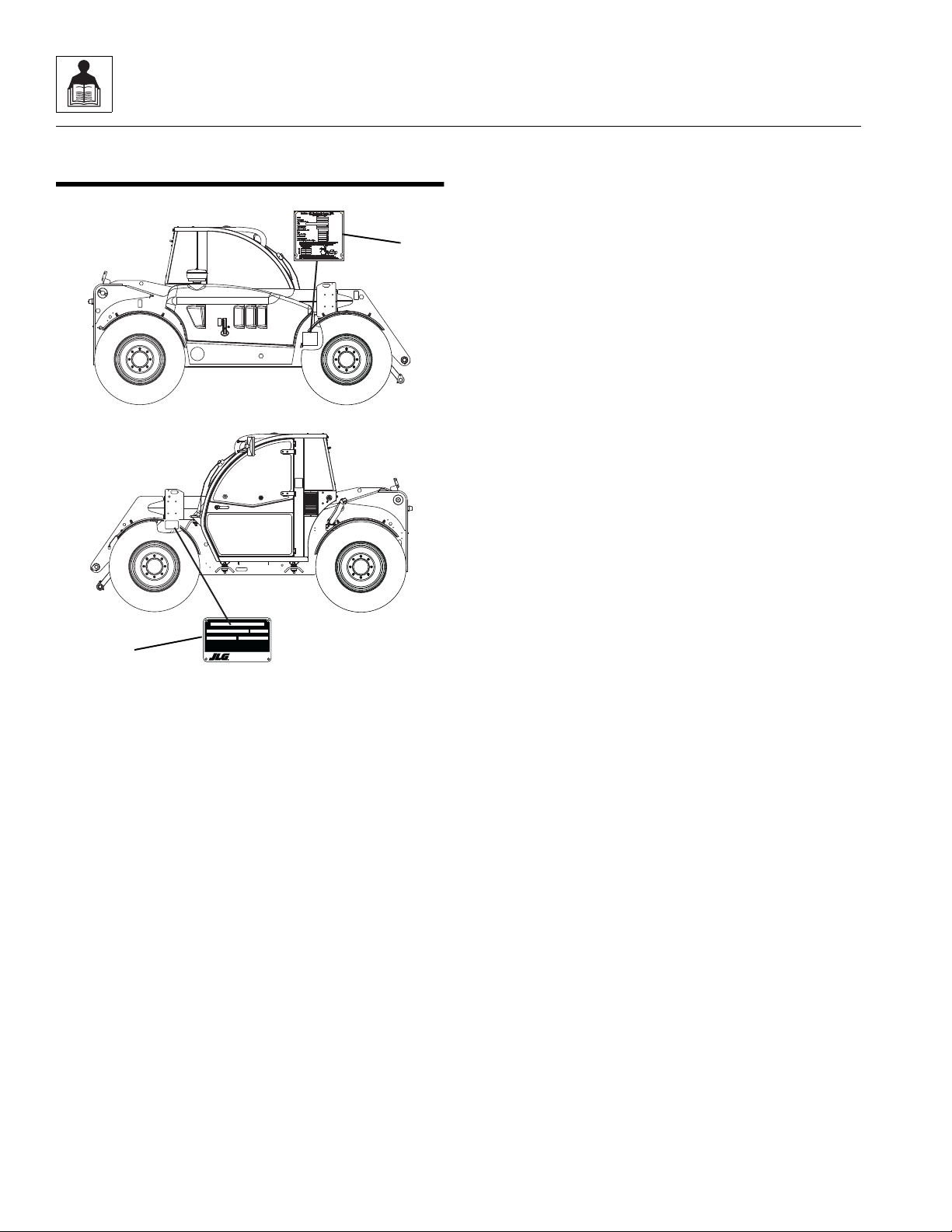
2.1 REPLACEMENT PARTS AND WARRANTY INFORMATION
Before ordering parts or initiating service inquiries, make
note of the machine serial number. The machine serial
number plate (1) is located as indicated in the figure.
Note: The replacement of any part on this machine with
any other th a n fa ct o ry au t h or iz ed re pl acement parts ca n
adversely affect the performance, durability, or safety of
the machine, and will void the warranty. JLG disclaims
liability for any claims or damages, whether regarding
property damage, personal injury or death arising out of
the use of unauthorized replacement parts.
A warranty registration form must be filled out by the local
JLG dealer, signed by the purchaser and returned to the
manufacturer when the machine is sold and/or put into
use.
Registration activates the warranty period and helps to
assure that warranty claims are promptly processed. To
guarantee full warranty service, verify that the local JLG
dealer has returned the business reply card of the
warranty registration form to the manufacturer.
2-2
L2906H, 2906H, 3507H, 619A, 723A, 29.6LP, 29.6, 35.7
Page 15
General Information and Specifications
MY3141
Size TPI Bolt Dia
Tensile
Stress Area
Clamp Load
In Sq In LB IN-LB [N.m] IN-LB [N.m] IN-LB [N.m] IN-LB [N.m]
4 40 0.1120 0.00604 380 8 0.9 6 0.7
48 0.1120 0.00661 420 9 1.0 7 0.8
6 32 0.1380 0.00909 580 16 1.8 12 1.4
40 0.1380 0.01015 610 18 2.0 13 1.5
8 32 0.1640 0.01400 900 30 3.4 22 2.5
36 0.1640 0.01474 940 31 3.5 23 2.6
10 24 0.1900 0.01750 1120 43 4.8 32 3.5
32 0.1900 0.02000 1285 49 5.5 36 4
1/4 20 0.2500 0.0318 2020 96 10.8 75 9 105 12
28 0.2500 0.0364 2320 120 13.5 86 10 135 15
In Sq In LB FT-LB [N.m] FT-LB [N.m] FT-LB [N.m] FT-LB [N.m]
5/16 18 0.3125 0.0524 3340 17 23 13 18 19 26 16 22
24 0.3125 0.0580 3700 19 26 14 19 21 29 17 23
3/8 16 0.3750 0.0775 4940 30 41 23 31 35 48 28 38
24 0.3750 0.0878 5600 35 47 25 34 40 54 32 43
7/16 14 0.4375 0.1063 6800 50 68 35 47 55 75 45 61
20 0.4375 0.1187 7550 55 75 40 54 60 82 50 68
1/2 13 0.5000 0.1419 9050 75 102 55 75 85 116 68 92
20 0.5000 0.1599 10700 90 122 65 88 100 136 80 108
9/16 12 0.5625 0.1820 11600 110 149 80 108 120 163 98 133
18 0.5625 0.2030 12950 120 163 90 122 135 184 109 148
5/8 11 0.6250 0.2260 14400 150 203 110 149 165 224 135 183
18 0.6250 0.2560 16300 170 230 130 176 190 258 153 207
3/4 10 0.7500 0.3340 21300 260 353 200 271 285 388 240 325
16 0.7500 0.3730 23800 300 407 220 298 330 449 268 363
7/8 9 0.8750 0.4620 29400 430 583 320 434 475 646 386 523
14 0.8750 0.5090 32400 470 637 350 475 520 707 425 576
1 8 1.0000 0.6060 38600 640 868 480 651 675 918 579 785
12 1.0000 0.6630 42200 700 949 530 719 735 1000 633 858
1 1/8 7 1.1250 0.7630 42300 800 1085 600 813 840 1142 714 968
12 1.1250 0.8560 47500 880 1193 660 895 925 1258 802 1087
1 1/4 7 1.2500 0.9690 53800 1120 1518 840 1139 1175 1598 1009 1368
12 1.2500 1.0730 59600 1240 1681 920 1247 1300 1768 1118 1516
1 3/8 6 1.3750 1.1550 64100 1460 1979 1100 1491 1525 2074 1322 1792
12 1.3750 1.3150 73000 1680 2278 1260 1708 1750 2380 1506 2042
1 1/2 6 1.5000 1.4050 78000 1940 2630 1460 1979 2025 2754 1755 2379
12 1.5000 1.5800 87700 2200 2983 1640 2224 2300 3128 1974 2676
NO. 5000059 REV. J
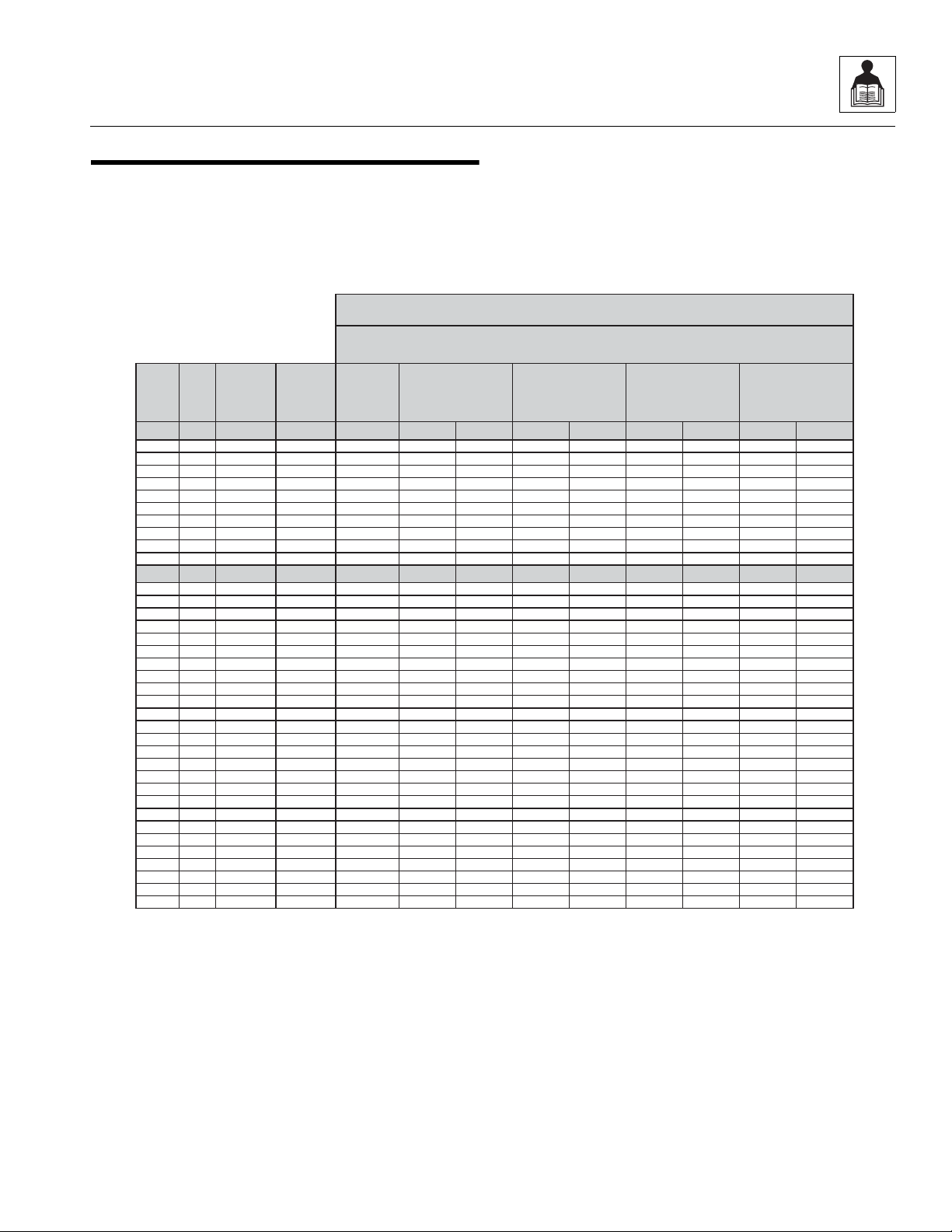
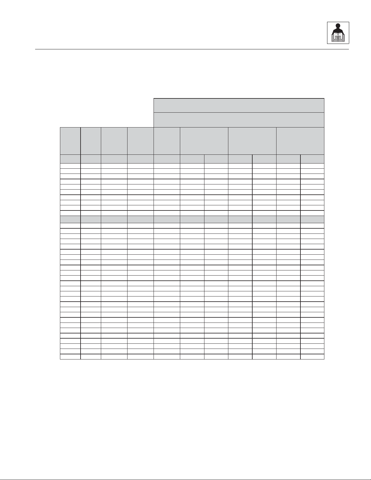
Values for Zinc Yellow Chromate Fasteners (Ref 4150707)
SAE GRADE 5 BOLTS & GRADE 2 NUTS
Torque
(Dry)
Torque
(Loctite® 262
TM
or Vibra-
TITE
TM
131)
Torque
Lubricated
Torque
(Loctite® 242
TM
or 271
TM
OR Vibra-TITETM111 or
140)
3. * ASSEMBLY USES HARDENED WASHER
NOTES: 1. THESE TORQUE VALUES DO NOTAPPLY TO CADMIUMPLATED FASTENERS
2. ALL TORQUE VALUESARE STATIC TORQUE MEASURED PER STANDARD AUDIT METHODS TOLERANCE = ±10%
2.2 TORQUES
2.2.1 SAE Fastener Torque Chart
L2906H, 2906H, 3507H, 619A, 723A, 29.6LP, 29.6, 35.7
2-3
Page 16
General Information and Specifications
MY3151
Size TPI Bolt Dia
Tensile
Stress Area
Clamp Load
In Sq In
4 40 0.1120 0.00604
48 0.1120 0.00661
6 32 0.1380 0.00909
40 0.1380 0.01015
8 32 0.1640 0.01400
36 0.1640 0.01474
10 24 0.1900 0.01750
32 0.1900 0.02000
1/4 20 0.2500 0.0318
28 0.2500 0.0364
In Sq In
5/16 18 0.3125 0.0524
24 0.3125 0.0580
3/8 16 0.3750 0.0775
24 0.3750 0.0878
7/16 14 0.4375 0.1063
20 0.4375 0.1187
1/2 13 0.5000 0.1419
20 0.5000 0.1599
9/16 12 0.5625 0.1820
18 0.5625 0.2030
5/8 11 0.6250 0.2260
18 0.6250 0.2560
3/4 10 0.7500 0.3340
16 0.7500 0.3730
7/8 9 0.8750 0.4620
14 0.8750 0.5090
1 8 1.0000 0.6060
12 1.0000 0.6630
1 1/8 7 1.1250 0.7630
12 1.1250 0.8560
1 1/4 7 1.2500 0.9690
12 1.2500 1.0730
1 3/8 6 1.3750 1.1550
12 1.3750 1.3150
1 1/2 6 1.5000 1.4050
12 1.5000 1.5800
NO. 5000059 REV. J
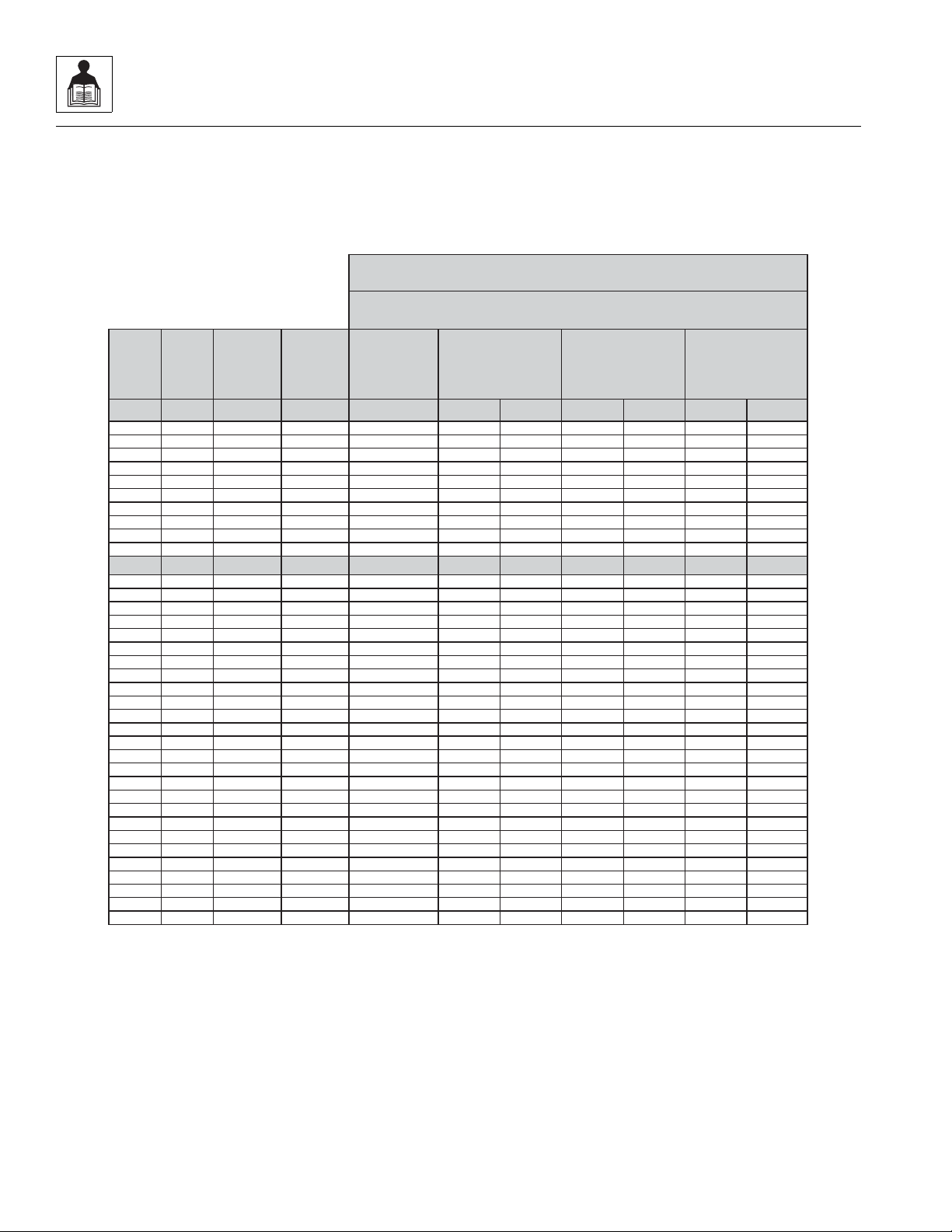
3. *ASSEMBLY USES HARDENED WASHER
NOTES: 1. THESE TORQUE VALUES DO NOT APPLY TO CADMIUM PLATED FASTENERS
2. ALL TORQUE VALUESARE STATICTORQUE MEASURED PER STANDARD AUDIT METHODS TOLERANCE = ±10%
LB IN-LB [N.m] IN-LB [N.m] IN-LB [N.m]
1320 43 5
1580 60 7
1800 68 8
2860 143 16 129 15
3280 164 19 148 17
LB FT-LB [N.m] FT-LB [N.m] FT-LB [N.m
4720 25 35 20 25 20 25
5220 25 35 25 35 20 25
7000 45 60 40 55 35 50
7900 50 70 45 60 35 50
9550 70 95 65 90 50 70
10700 80 110 70 95 60 80
12750 105 145 95 130 80 110
14400 120 165 110 150 90 120
16400 155 210 140 190 115 155
18250 170 230 155 210 130 175
20350 210 285 190 260 160 220
23000 240 325 215 290 180 245
30100 375 510 340 460 280 380
33600 420 570 380 515 315 430
41600 605 825 545 740 455 620
45800 670 910 600 815 500 680
51500 860 1170 770 1045 645 875
59700 995 1355 895 1215 745 1015
68700 1290 1755 1160 1580 965 1310
77000 1445 1965 1300 1770 1085 1475
87200 1815 2470 1635 2225 1365 1855
96600 2015 2740 1810 2460 1510 2055
104000 2385 3245 2145 2915 1785 2430
118100 2705 3680 2435 3310 2030 2760
126500 3165 4305 2845 3870 2370 3225
142200 3555 4835 3200 4350 2665 3625
Torque
(Loctite® 242
TM
or 271
TM
OR Vibra-TITETM111 or
140) K=.18
Torque
(Loctite® 262
TM
or Vibra-
TITE
TM
131)
K=0.15
SAE GRADE 8 (HEX HD) BOLTS & GRADE 8 NUTS*
Torque
(Dry orLoctite® 263)
K= 0.20
2.2.1 SAE Fastener Torque Chart
(Continued)
2-4
L2906H, 2906H, 3507H, 619A, 723A, 29.6LP, 29.6, 35.7
Page 17
General Information and Specifications
MY3161
Size TPI Bolt Dia
Tensile
Stress Area
Clamp Load
See Note4
In Sq In LB IN-LB [N.m] IN-LB [N.m] IN-LB [N.m]
4 40 0.1120 0.00604
48 0.1120 0.00661
6 32 0.1380 0.00909
40 0.1380 0.01015
8 32 0.1640 0.01400
36 0.1640 0.01474
10 24 0.1900 0.01750
32 0.1900 0.02000
1/4 20 0.2500 0.0318 2860 122 14 114 13
28 0.2500 0.0364 3280 139 16 131 15
In Sq In LB FT-LB [N.m] FT-LB [N.m] FT-LB [N.m]
5/16 18 0.3125 0.0524 4720 20 25 20 25 20 25
24 0.3125 0.0580 5220 25 35 20 25 20 25
3/8 16 0.3750 0.0775 7000 35 50 35 50 35 50
24 0.3750 0.0878 7900 40 55 40 55 35 50
7/16 14 0.4375 0.1063 9550 60 80 55 75 50 70
20 0.4375 0.1187 10700 65 90 60 80 60 80
1/2 13 0.5000 0.1419 12750 90 120 85 115 80 110
20 0.5000 0.1599 14400 100 135 95 130 90 120
9/16 12 0.5625 0.1820 16400 130 175 125 170 115 155
18 0.5625 0.2030 18250 145 195 135 185 130 175
5/8 11 0.6250 0.2260 20350 180 245 170 230 160 220
18 0.6250 0.2560 23000 205 280 190 260 180 245
3/4 10 0.7500 0.3340 30100 320 435 300 410 280 380
16 0.7500 0.3730 33600 355 485 335 455 315 430
7/8 9 0.8750 0.4620 41600 515 700 485 660 455 620
14 0.8750 0.5090 45800 570 775 535 730 500 680
1 8 1.0000 0.6060 51500 730 995 685 930 645 875
12 1.0000 0.6630 59700 845 1150 795 1080 745 1015
1 1/8 7 1.1250 0.7630 68700 1095 1490 1030 1400 965 1310
12 1.1250 0.8560 77000 1225 1665 1155 1570 1085 1475
1 1/4 7 1.2500 0.9690 87200 1545 2100 1455 1980 1365 1855
12 1.2500 1.0730 96600 1710 2325 1610 2190 1510 2055
1 3/8 6 1.3750 1.1550 104000 2025 2755 1905 2590 1785 2430
12 1.3750 1.3150 118100 2300 3130 2165 2945 2030 2760
1 1/2 6 1.5000 1.4050 126500 2690 3660 2530 3440 2370 3225
12 1.5000 1.5800 142200 3020 4105 2845 3870 2665 3625
NO. 5000059 REV. J
4. CLAMPLOAD LISTEDFOR SHCS IS SAMEAS GRADE 8 OR CLASS 10.9 AND DOES NOT REPRESENT FULL STRENGTH
CAPABILITYOF SHCS.IF HIGHER LOAD IS REQUIRED, ADDITIONALTESTING ISREQUIRED.
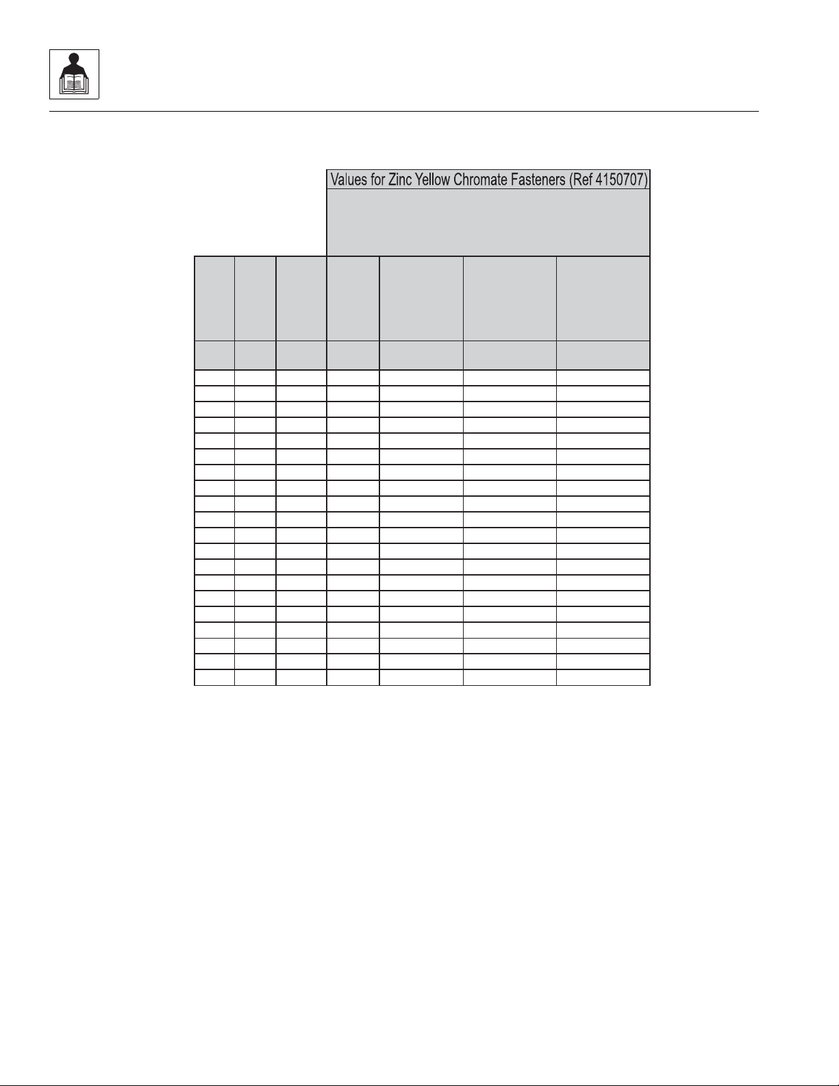
SOCKET HEAD CAP SCREWS
Magni Coating (Ref 4150701)*
Torque
(Dry) K = .17
Torque
(Loctite® 242
TM
or 271
TM
OR Vibra-TITETM111 or
140 ORPrecoat 85®
K=0.16
Torque
(Loctite® 262
TM
or Vibra-
TITE
TM
131)
K=0.15
2. ALL TORQUE VALUESARE STATICTORQUE MEASURED PER STANDARD AUDIT METHODS TOLERANCE = ±10%
NOTES: 1.THESE TORQUE VALUESDO NOTAPPLY TO CADMIUM PLATED FASTENERS
*3. ASSEMBLY USES HARDENED WASHER OR FASTENER IS PLACED AGAINST PLATEDSTEEL OR RAWALUMINUM
2.2.1 SAE Fastener Torque Chart
(Continued)
L2906H, 2906H, 3507H, 619A, 723A, 29.6LP, 29.6, 35.7
2-5
Page 18
General Information and Specifications
Size TPI Bolt Dia
Tensile
Stress Area
Clamp Load
See Note4
In Sq In LB IN-LB [N.m] IN-LB [N.m] IN-LB [N.m]
4 40 0.1120 0.00604
48 0.1120 0.00661
6 32 0.1380 0.00909
40 0.1380 0.01015
8 32 0.1640 0.01400
36 0.1640 0.01474
10 24 0.1900 0.01750
32 0.1900 0.02000
1/4 20 0.2500 0.0318 2860 143 16 129 15
28 0.2500 0.0364 3280 164 19 148 17
In Sq In LB FT-LB [N.m] FT-LB [N.m] FT-LB [N.m]
5/16 18 0.3125 0.0524 4720 25 35 20 25 20 25
24 0.3125 0.0580 5220 25 35 25 35 20 25
3/8 16 0.3750 0.0775 7000 45 60 40 55 35 50
24 0.3750 0.0878 7900 50 70 45 60 35 50
7/16 14 0.4375 0.1063 9550 70 95 65 90 50 70
20 0.4375 0.1187 10700 80 110 70 95 60 80
1/2 13 0.5000 0.1419 12750 105 145 95 130 80 110
20 0.5000 0.1599 14400 120 165 110 150 90 120
9/16 12 0.5625 0.1820 16400 155 210 140 190 115 155
18 0.5625 0.2030 18250 170 230 155 210 130 175
5/8 11 0.6250 0.2260 20350 210 285 190 260 160 220
18 0.6250 0.2560 23000 240 325 215 290 180 245
3/4 10 0.7500 0.3340 30100 375 510 340 460 280 380
16 0.7500 0.3730 33600 420 570 380 515 315 430
7/8 9 0.8750 0.4620 41600 605 825 545 740 455 620
14 0.8750 0.5090 45800 670 910 600 815 500 680
1 8 1.0000 0.6060 51500 860 1170 775 1055 645 875
12 1.0000 0.6630 59700 995 1355 895 1215 745 1015
1 1/8 7 1.1250 0.7630 68700 1290 1755 1160 1580 965 1310
12 1.1250 0.8560 77000 1445 1965 1300 1770 1085 1475
1 1/4 7 1.2500 0.9690 87200 1815 2470 1635 2225 1365 1855
12 1.2500 1.0730 96600 2015 2740 1810 2460 1510 2055
1 3/8 6 1.3750 1.1550 104000 2385 3245 2145 2915 1785 2430
12 1.3750 1.3150 118100 2705 3680 2435 3310 2030 2760
1 1/2 6 1.5000 1.4050 126500 3165 4305 2845 3870 2370 3225
12 1.5000 1.5800 142200 3555 4835 3200 4350 2665 3625
NO. 5000059 REV. J
4. CLAMPLOAD LISTED FOR SHCS IS SAMEAS GRADE 8 OR CLASS 10.9 AND DOES NOT REPRESENT FULL STRENGTH
CAPABILITYOF SHCS. IF HIGHER LOAD IS REQUIRED, ADDITIONALTESTING ISREQUIRED.
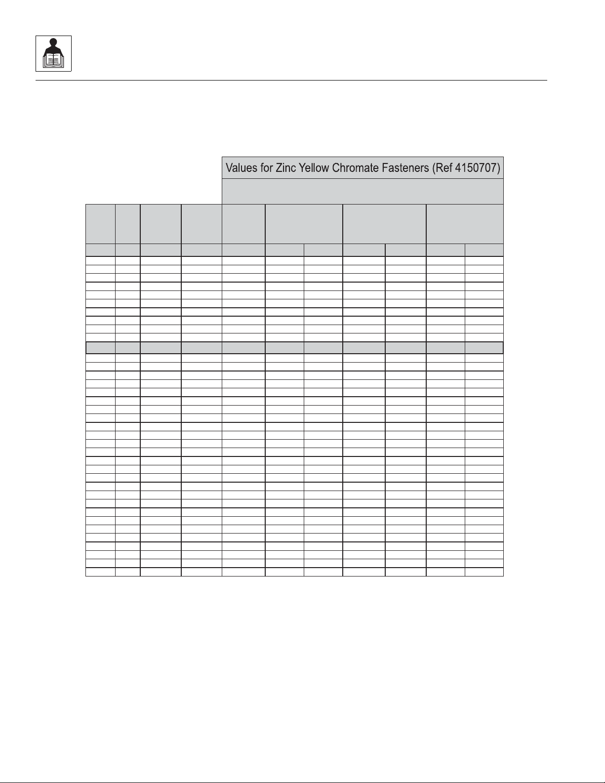
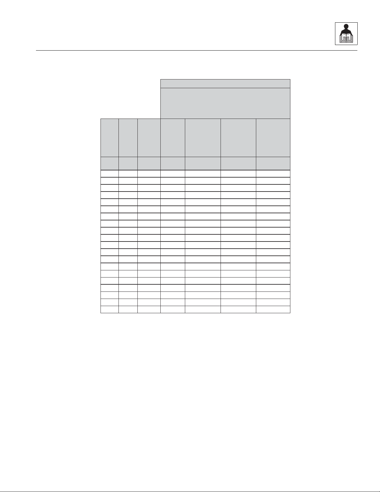
SOCKET HEAD CAP SCREWS
Torque
(Dry)
K=.20
Torque
(Loctite® 242
TM
or 271
TM
OR Vibra-TITETM111 or
140 ORPrecoat 85®
K=0.18
Zinc Yellow Chromate Fasteners (Ref 4150707)*
2. ALL TORQUE VALUESARE STATICTORQUE MEASURED PER STANDARDAUDIT METHODSTOLERANCE = ±10%
NOTES: 1.THESE TORQUE VALUESDO NOTAPPLYTO CADMIUM PLATEDFASTENERS
*3. ASSEMBLY USES HARDENED WASHER OR FASTENER IS PLACED AGAINST PLATEDSTEEL OR RAWALUMINUM
Torque
(Loctite® 262
TM
or Vibra-
TITE
TM
131)
K=0.15
MY3400
2.2.1 SAE Fastener Torque Chart
(Continued)
2-6
L2906H, 2906H, 3507H, 619A, 723A, 29.6LP, 29.6, 35.7
Page 19

2.2.2 Metric Fastener Torque Chart
MY3171
SizePITCH
Tensile
Stress
Area
Clamp
Load
Torque
(Dry orLoctite®
263
TM
)
Torque
(Lub)
Torque
(Loctite® 262
TM
OR Vibra-
TITE
TM
131)
Torque
(Loctite®
242
TM
or 271
TM
OR Vibra-
TITE
TM
111 or
140)
Sq mm KN [N.m] [N.m] [N.m] [N.m]
3 0.5 5.03 2.19 1.3 1.0 1.2 1.4
3.5 0.6 6.78 2.95 2.1 1.6 1.9 2.3
4 0.7 8.78 3.82 3.1 2.3 2.8 3.4
5 0.8 14.20 6.18 6.2 4.6 5.6 6.8
6 1 20.10 8.74 11 7.9 9.4 12
7 1 28.90 12.6 18 13 16 19
8 1.25 36.60 15.9 26 19 23 28
10 1.5 58.00 25.2 50 38 45 55
12 1.75 84.30 36.7 88 66 79 97
14 2 115 50.0 140 105 126 154
16 2 157 68.3
219 164 197 241
18 2.5 192 83.5 301 226 271 331
20 2.5 245 106.5 426 320 383 469
22 2.5 303 132.0 581 436 523 639
24 3 353 153.5 737 553 663 811
27 3 459 199.5 1080 810 970 1130
30 3.5 561 244.0 1460 1100 1320 1530
33 3.5 694 302.0 1990 1490 1790 2090
36 4 817 355.5 2560 1920 2300 2690
42 4.5 1120 487.0 4090 3070 3680 4290
4. CLAMPLOAD LISTEDFOR SHCS IS SAMEAS GRADE 8 OR CLASS 10.9 AND DOES NOT
REPRESENT FULL STRENGTH CAPABILITY OF SHCS. IFHIGHER LOAD IS REQUIRED,
ADDITIONAL TESTING IS REQUIRED.
*3. ASSEMBLY USES HARDENED WASHER OR FASTENER IS PLACED AGAINST PLATED
STEEL OR RAWALUMINUM
CLASS 8.8 METRIC BOLTS
CLASS 8 METRIC NUTS
NOTES: 1.THESE TORQUE VALUESDO NOTAPPLY TO CADMIUM PLATED FASTENERS
2. ALL TORQUE VALUESARE STATICTORQUE MEASURED PER STANDARD AUDIT
METHODS TOLERANCE = ±10%
NO. 5000059 REV. J
General Information and Specifications
L2906H, 2906H, 3507H, 619A, 723A, 29.6LP, 29.6, 35.7
2-7
Page 20
General Information and Specifications
MY3181
SizePITCH
Tensile
Stress
Area
Clamp
Load
Torque
(Dry orLoctite®
263
TM
)
K =0.20
Torque
(Lub ORLoctite®
242
TM
or 271TMOR
Vibra-TITE
TM
111 or
140)
K= 0.18
Torque
(Loctite® 262
TM
OR
Vibra-TITE
TM
131)
K=0.15
Sq mm KN [N.m] [N.m] [N.m]
3 0.5 5.03 3.13
3.5 0.6 6.78 4.22
4 0.7 8.78 5.47
5 0.8 14.20 8.85
6 1 20.10 12.5
7 1 28.90 18.0 25.2 22.7 18.9
8 1.25 36.60 22.8 36.5 32.8 27.4
10 1.5 58.00 36.1 70 65 55
12 1.75 84.30 52.5 125 115 95
14 2 115 71.6 200 180 150
16 2 157 97.8
315 280 235
18 2.5 192 119.5 430 385 325
20 2.5 245 152.5 610 550 460
22 2.5 303 189.0 830 750 625
24 3 353 222.0 1065 960 800
27 3 459 286.0 1545 1390 1160
30 3.5 561 349.5 2095 1885 1575
33 3.5 694 432.5 2855 2570 2140
36 4 817 509.0 3665 3300 2750
42 4.5 1120 698.0 5865 5275 4395
CLASS 10.9 METRIC BOLTS
CLASS 10 METRIC NUTS
CLASS 12.9 SOCKET HEAD CAP SCREWS M3 - M5*
4. CLAMPLOAD LISTEDFOR SHCS IS SAMEAS GRADE 8 OR CLASS 10.9 AND DOES NOT
REPRESENT FULL STRENGTH CAPABILITY OF SHCS. IFHIGHER LOAD IS REQUIRED,
ADDITIONAL TESTING IS REQUIRED.
*3. ASSEMBLY USES HARDENED WASHER OR FASTENER IS PLACED AGAINST PLATED
STEEL OR RAWALUMINUM
NOTES: 1.THESE TORQUE VALUESDO NOTAPPLY TO CADMIUM PLATED FASTENERS
2. ALL TORQUE VALUESARE STATICTORQUE MEASURED PER STANDARD AUDIT
METHODS TOLERANCE = ±10%
NO. 5000059 REV. J
2.2.2 Metric Fastener Torque Chart
(Continued)
2-8
L2906H, 2906H, 3507H, 619A, 723A, 29.6LP, 29.6, 35.7
Page 21
2.2.2 Metric Fastener Torque Chart
MY3191
SizePITCH
Tensile
Stress
Area
Clamp Load
See Note4
Torque
(Dry orLoctite®
263
TM
)
K =.17
Torque
(Lub ORLoctite®
242
TM
or 271
TM
OR Vibra-TITE
TM
111 or 140)
K =.16
Torque
(Loctite® 262
TM
OR Vibra-TITE
TM
131)
K=.15
Sq mm kN [N.m] [N.m] [N.m]
3 0.5 5.03
3.5 0.6 6.78
4 0.7 8.78
5 0.8 14.20
6 1 20.10 12.5 13 12 11
7 1 28.90 18.0 21 20 19
8 1.25 36.60 22.8 31 29 27
10 1.5 58.00 36.1 61 58 54
12 1.75 84.30 52.5 105 100 95
14 2 115 71.6 170 160 150
16 2 157
97.8 265 250 235
18 2.5 192 119.5 365 345 325
20 2.5 245 152.5 520 490 460
22 2.5 303 189.0 705 665 625
24 3 353 220.0 900 845 790
27 3 459 286.0 1315 1235 1160
30 3.5 561 349.5 1780 1680 1575
33 3.5 694 432.5 2425 2285 2140
36 4 817 509.0 3115 2930 2750
42 4.5 1120 698.0 4985 4690 4395
CLASS 12.9 SOCKET HEAD CAP SCREWS
M6 ANDABOVE*
4. CLAMPLOAD LISTEDFOR SHCS IS SAMEAS GRADE 8 OR CLASS 10.9 AND DOES NOT
REPRESENT FULL STRENGTH CAPABILITY OF SHCS. IFHIGHER LOAD IS REQUIRED,
ADDITIONAL TESTING IS REQUIRED.
*3. ASSEMBLY USES HARDENED WASHER OR FASTENER IS PLACED AGAINST PLATED
STEEL OR RAWALUMINUM
NOTES: 1.THESE TORQUE VALUESDO NOTAPPLY TO CADMIUM PLATED FASTENERS
2. ALL TORQUE VALUESARE STATICTORQUE MEASURED PER STANDARD AUDIT
METHODS TOLERANCE = ±10%
NO. 5000059 REV. J
Magni Coating (Ref 4150701)*
(Continued)
General Information and Specifications
L2906H, 2906H, 3507H, 619A, 723A, 29.6LP, 29.6, 35.7
2-9
Page 22

General Information and Specifications
2.2.3 Hydraulic Hose Torque Chart
O-Ring Face Seal & JIC Torque Chart
Size ORFS JIC Flats Method
10
12
16
20
24
4
6
8
18 Nm
(13 lb-ft)
31 Nm
(23 lb-ft)
54 Nm
(40 lb-ft)
81 Nm
(60 lb-ft)
100 Nm
(136 lb-ft)
156 Nm
(115 lb-ft)
230 Nm
(170 lb-ft)
271 Nm
(200 lb-ft)
18 Nm
(13 lb-ft)
31 Nm
(23 lb-ft)
54 Nm
(40 lb-ft)
81 Nm
(60 lb-ft)
115 Nm
(85 lb-ft)
156 Nm
(115 lb-ft)
230 Nm
(170 lb-ft)
271 Nm
(200 lb-ft)
1.5 to 1.75
1 to 1.5
1.5 to 1.75
1.5 to 1.75
1.0 to 1.5
.75 to 1.0
.75 to 1.0
.75 to 1.0
Flats Method:
1. If equipped, lubricate o-ring with hydraulic oil. Hand
tighten the swivel nut until no lateral movement of
the swivel nut can be detected. Average hand torque
is 4 Nm (3 lb-ft).
2. Mark a dot on one of the swivel nut flats and another
dot in line on the hex of the adapter it’s connecting
to.
3. Use the double wrench method while tightening to
avoid hose twist.
4. After the connection has been properly tightened,
mark a straight line across the connecting parts, not
covering the dots indicating that the con necti on has
been properly tightened.
32 N/A
366 Nm
(270 lb-ft)
.75 to 1.0
Note: By definition the “Flats Method“ will contain some
variance. Use the “Flats Method” only when accessibility
with a torque wrench is not possible.
Torque Wrench:
1. Identify the appropriate application and refer to the
above chart for the correct torque value.
2. If equipped, lubricate o-ring with hydraulic oil. Hand
tighten the swivel nut until no lateral movement of
the swivel nut can be detected. Average hand torque
is 4 Nm (3 lb-ft).
3. Use the double wrench method while tightening to
avoid hose twist.
4. Torque wrench must be held at the center of the grip.
Apply constant force until it clicks.
5. After the connection has been properly tightened,
mark a straight line across the connecting parts
indicating that the connection has been properly
tightened.
2-10
L2906H, 2906H, 3507H, 619A, 723A, 29.6LP, 29.6, 35.7
Page 23

General Information and Specifications
2.3 SPECIFICATIONS
2.3.1 Travel Speed
L2906H, 2906H, 29.9LP, 29.6 & 619A 3507H, 35.7 & 723A
First Gear 10 kmph (6 mph) 7 kmph (4 mph)
Second Gear 34 kmph (21 mph) 33 kmph (20 mph)
2.3.2 Hydraulic Cylinder Performance Specifications
Note: Machine with no load, engine at full throttle, hydraulic oil above 54° C (130° F) minimum, engine at operating
temperature.
Function Approximate Times (sec.)
Boom Extend 6
Boom Retract 4
Boom Lift 6
Boom Lower 4
Quick Attach - UP 2
Quick Attach - DOWN 2
2.3.3 Electrical System
Note: Refer to Section 9.8, “Fuses and Relays,” for more information.
Battery
Type, Rating 12V, Negative (-) Ground, Tapered Top Post, Maintenance Free
Quantity 1
Reserve Capacity 1000 Cold Cranking Amps @ -18° C (0° F)
Group/Series BCI Group 31
Alternator 12V, 95 Amps
Starter 12V, 3,0 KW Type EV (Gear Reduction)
L2906H, 2906H, 3507H, 619A, 723A, 29.6LP, 29.6, 35.7
2-11
Page 24

General Information and Specifications
2.3.4 Engine Performance Specifications
Description
Engine Make/Model Deutz TCD2012L04V02 Tier III
Low Idle 925 ±50 rpm
High Idle 2370 ±50 rpm
Horsepower 74.9 kW/100.4 BHP @ 2200 rpm
Fuel Delivery Fuel Injection
Air Cleaner Dry Type, Replaceable Primary and Safety Elements
Average Fuel Consumption (dependant on load/duty) 6,1 I/hr (1.6 gal/hr)
2.3.5 Tires
Note: Standard wheel lug nut torque is 300 Nm (220 lb-ft).
Note: Pressures for Foam filled tires are for initial fill ONLY.
Size Tire
405/70-20
(L2906H, 2906H & 3507H)
405/70-24
(2906H, 3507H, 29.6 & 35.7)
405/70-20
(L2906H, 2906H,3507H & 619A)
405/70-20
(619A)
405/70-24
(2906H, 3507H, 29.6, 35.7 & 723A)
405/70-24
(723A)
400/70R20 XMCL Radial Ply Pneumatic 4 bar (58 psi)
445/70R24
(3507H, 35.7 & 723A)
460/70R24
(3507H, 35.7 & 723A)
Minimum Ply/
Type
MPT-01 Bias - 14 Ply Pneumatic 3,5 bar (51 psi)
MPT-01 Bias - 14 Ply Pneumatic 4,0 bar (58 psi)
MPT-04 Bias - 14 Ply Pneumatic 3,5 bar (51 psi)
MPT-04 Bias - 14 Ply
MPT-04 Bias - 14 Ply Pneumatic 4 bar (58 psi)
MPT-04 Bias - 14 Ply
XMCL Radial Ply Pneumatic 4,1 bar (60 psi)
EM-01 Radial Ply Pneumatic 4 bar (58 psi)
Star Rating
Fill Type Pressure
Foam - Approx. 200 kg
(441 lb)
Foam - Approx. 240 kg
(529 lb)
2-12
L2906H, 2906H, 3507H, 619A, 723A, 29.6LP, 29.6, 35.7
Page 25

General Information and Specifications
2.4 FLUIDS, LUBRICANTS AND CAPACITIES
Engine Crankcase Oil
Capacity w/Filter Change 10,4 liter (11 quart)
Filter Capacity 1,0 liter (1.05 quart)
Oil Type
L2906H, 2906H, 3507H, 619A & 723A 15W-40 CE
29.6LP, 29.6 & 35.7 DF Super ENGINE OIL 15W-40
Fuel Filters
Primary Fuel Filter Capacity Approx. 1,0 liter (1.05 quart)
Fuel Filter Capacity 0,6 liter (0.16 quart)
Fuel Tank
Capacity
L2906H, 2906H, 29.6LP, 29.6 & 619A 95 liter (25 gallon)
3507H, 35.7 & 723A 102 liter (27 gallon)
Type of Fuel #2 Diesel
Cooling System
System Capacity w/o Heater 19 liter (5 gallon)
Overflow Bottle Capacity 3 liter (3.2 gallon)
Type of Fluid 50/50 mix of ethylene glycol & water
Hydraulic System
System Capacity
L2906H, 2906H, 29.6LP, 29.6 & 619A 98 liter (26 gallon)
3507H, 35.7 & 723A 102 liter (27 gallon)
Reservoir Capacity to FULL Mark
L2906H, 2906H, 29.6LP, 29.6 & 619A 60 liter (16 gallon)
3507H, 35.7 & 723A 95 liter (25 gallon)
Type of Fluid
L2906H, 2906H 3507H,619A & 723A Mobilfluid
®
424Tractor Hydraulic Fluid (ISO 46)
29.6LP, 29.6 & 35.7 DF UTTO Tractor Hydraulic Fluid
Air Conditioning
Capacity 1,1 kg (2.4 lb)
Type of Refrigerant R-134a
L2906H, 2906H, 3507H, 619A, 723A, 29.6LP, 29.6, 35.7
2-13
Page 26

General Information and Specifications
Axles
Differential Housing Capacity - Front
L2906H, 2906H, 29.6LP, 29.6 & 619A 9,5 liter (10 quart)
3507H, 35.7 & 723A 10 liter (10.6 quart)
Differential Housing Capacity - Rear
L2906H, 2906H, 29.6LP, 29.6 & 619A 5,5 liter (5,8 quart)
3507H, 35.7 & 723A 8 liter (8.5 quart)
Wheel End Capacity
L2906H, 2906H, 29.6LP, 29.6 & 619A 0,8 liter (0.8 quart)
3507H, 35.7 & 723A
Front - 0,6 liter (0.6 quart)
Rear - 0,7 liter (0.7 quart)
Transfer Box
Capacity 0,5 liter (0.5 quart)
T ype of Flui d
Mobilube HDLS 80W-90,
L2906H, 2906H 3507H,619A & 723A
Mobilfluid
®
424Tractor Hydraulic Fluid (ISO 46), Shell Spirax LS,
Esso Torque Fluid 62, Selenia Ambra STF 80W-90
29.6LP, 29.6 & 35.7 DF GEAR 90 LS
Brakes
Master Cylinder Capacity 0,7 liter (0.7 quart)
2-14
L2906H, 2906H, 3507H, 619A, 723A, 29.6LP, 29.6, 35.7
Page 27
General Information and Specifications
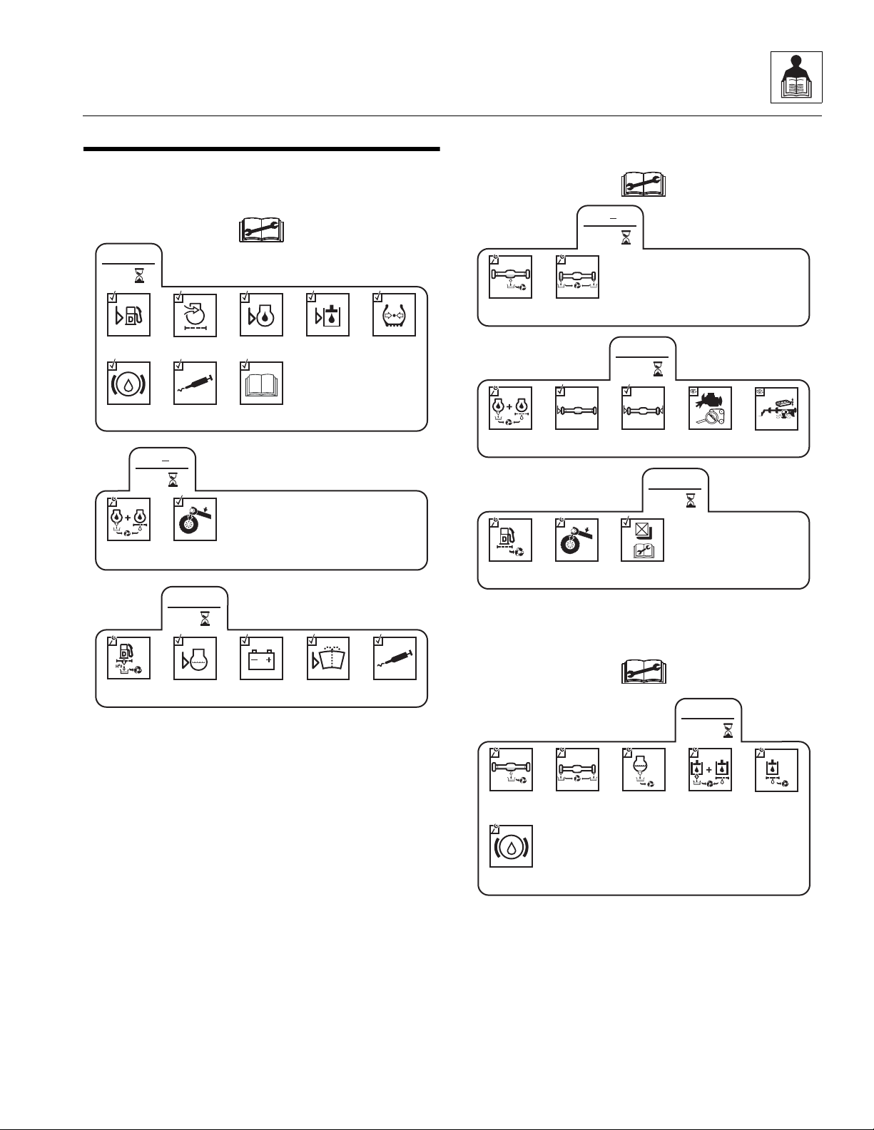
OAH18702
50
EVERY
Drain Fuel/
Water
Separator
Check Engine
Coolant Level
Check
Battery
Lubrication
Schedule
Check Washer
Fluid Level
(if equipped)
50
1
st
Check Wheel
Lug Nut
Torque
LB/FT (Nm)
Change Engine
Oil and
Filter
Check Fuel
Level
10
EVERY
Lubrication
Schedule
Additional
Checks Section 8
Check
Air Precleaner
Check Engine
Oil Level
Check Hydraulic
Oil Level
Check Tire
Condition &
Pressure
Check Brake
Fluid Level
OAH18812
150
1
st
Change Axle
Differential Oil
Change Wheel
End Oil
250
EVERY
Check Axle
Differential Oil
Level
Check Wheel
End Oil Level
Change Engine
Oil and Filter
Check
Fan Belt
Check Boom
Wear Pads
Check LSI
Calibration
500
EVERY
Check Wheel
Lug Nut
Torque
LB/FT (Nm)
Change Fuel
Filters
OAH18902
1500
EVERY
Change
Engine Coolant
Change
Hydraulic
Fluid & Filters
Change
Hydraulic Tank
Breather
Change Axle
Differential Oil
Change Wheel
End Oil
Change
Brake Fluid
2.5 MAINTENANCE SCHEDULES
2.5.1 10,1st 50 & 50 Hour Maintenance Schedule
2.5.2 1st 150, 250 & 500 Hour Maintenance Schedule
2.5.3 1500 Hour Maintenance Schedule
L2906H, 2906H, 3507H, 619A, 723A, 29.6LP, 29.6, 35.7
2-15
Page 28
General Information and Specifications
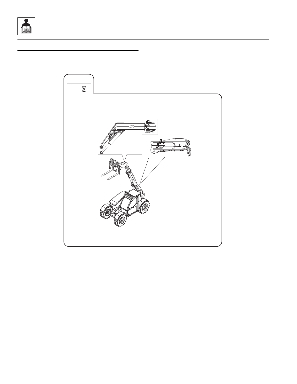
OAH1900
EVERY
10
2.6 LUBRICATION SCHEDULE
2.6.1 10 Hour Lubrication Schedule
2-16
L2906H, 2906H, 3507H, 619A, 723A, 29.6LP, 29.6, 35.7
Page 29
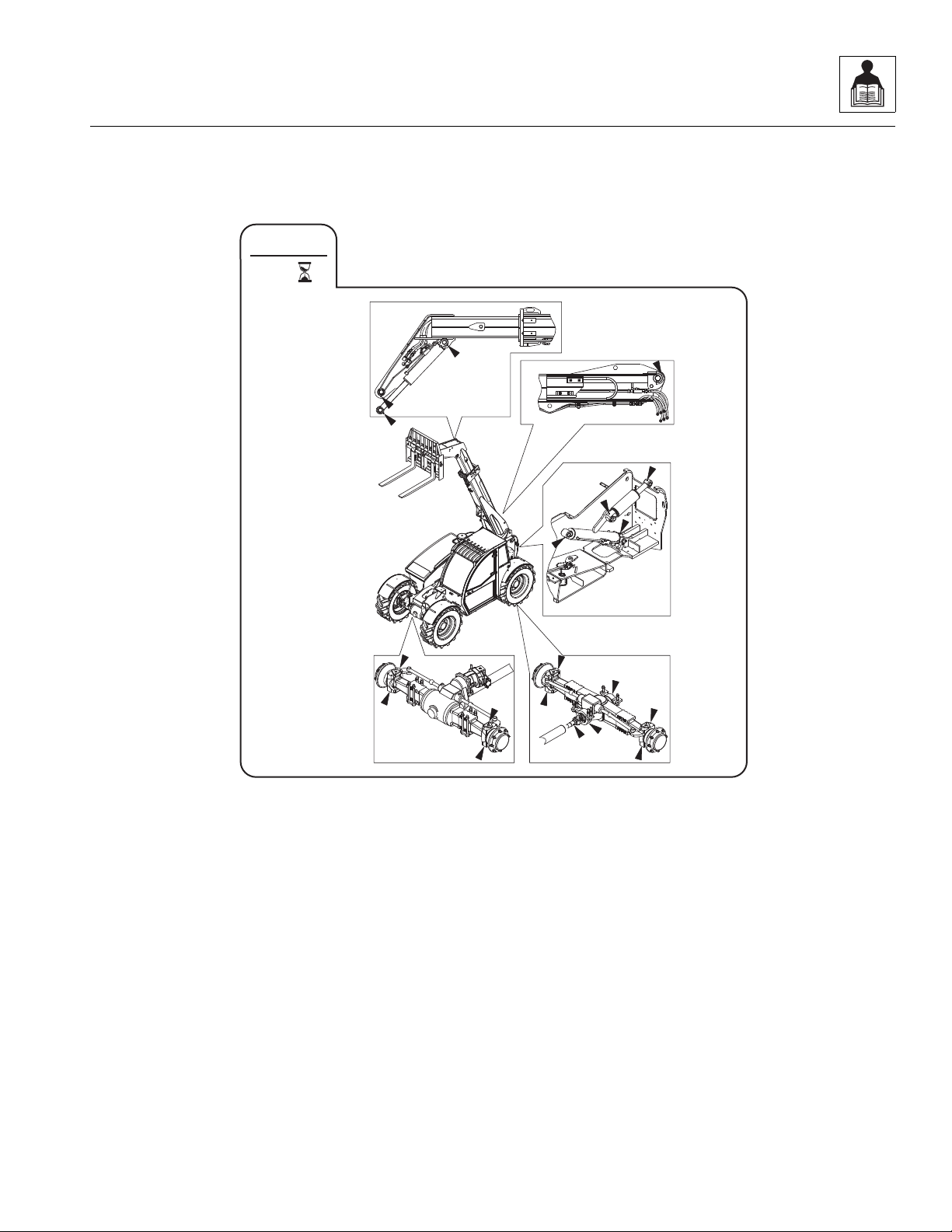
2.6.2 50 Hour Lubrication Schedule
OAH1910
EVERY
50
General Information and Specifications
L2906H, 2906H, 3507H, 619A, 723A, 29.6LP, 29.6, 35.7
2-17
Page 30

General Information and Specifications
This Page Intentionally Left Blank
2-18
L2906H, 2906H, 3507H, 619A, 723A, 29.6LP, 29.6, 35.7
Page 31

Section 3
Boom
Contents
PARAGRAPH TITLE PAGE
3.1 Boom System Component Terminology. . . . . . . . . . . . . . . . . . . . . . . . . . . . . . . . 3-2
3.2 Safety Information. . . . . . . . . . . . . . . . . . . . . . . . . . . . . . . . . . . . . . . . . . . . . . . . . . 3-3
3.3 Boom System - Two Section Boom. . . . . . . . . . . . . . . . . . . . . . . . . . . . . . . . . . . . 3-3
3.4 Boom Assembly Maintenance. . . . . . . . . . . . . . . . . . . . . . . . . . . . . . . . . . . . . . . . 3-3
3.4.1 Boom Removal . . . . . . . . . . . . . . . . . . . . . . . . . . . . . . . . . . . . . . . . . . . . . 3-3
3.4.2 Second Section Boom Removal. . . . . . . . . . . . . . . . . . . . . . . . . . . . . . . . 3-4
3.4.3 Second Section Boom Installation . . . . . . . . . . . . . . . . . . . . . . . . . . . . . . 3-5
3.4.4 Boom Installation. . . . . . . . . . . . . . . . . . . . . . . . . . . . . . . . . . . . . . . . . . . . 3-5
3.4.5 Extend/Retract Cylinder Removal. . . . . . . . . . . . . . . . . . . . . . . . . . . . . . . 3-6
3.4.6 Extend/Retract Cylinder Installation . . . . . . . . . . . . . . . . . . . . . . . . . . . . . 3-7
3.5 Boom Wear Pads. . . . . . . . . . . . . . . . . . . . . . . . . . . . . . . . . . . . . . . . . . . . . . . . . . . 3-8
3.5.1 Wear Pad Inspection. . . . . . . . . . . . . . . . . . . . . . . . . . . . . . . . . . . . . . . . . 3-8
3.5.2 Wear Pad Installation and Lubrication . . . . . . . . . . . . . . . . . . . . . . . . . . . 3-8
3.6 Quick Attach Assembly . . . . . . . . . . . . . . . . . . . . . . . . . . . . . . . . . . . . . . . . . . . . . 3-9
3.6.1 Quick Attach Removal. . . . . . . . . . . . . . . . . . . . . . . . . . . . . . . . . . . . . . . . 3-9
3.6.2 Quick Attach Installation . . . . . . . . . . . . . . . . . . . . . . . . . . . . . . . . . . . . . . 3-9
3.7 Forks . . . . . . . . . . . . . . . . . . . . . . . . . . . . . . . . . . . . . . . . . . . . . . . . . . . . . . . . . . . .3-10
3.8 Boom Prop (If Equipped) . . . . . . . . . . . . . . . . . . . . . . . . . . . . . . . . . . . . . . . . . . . . 3-10
3.8.1 Installation and Removal Procedures . . . . . . . . . . . . . . . . . . . . . . . . . . . . 3-10
3.9 Emergency Boom Lowering Procedure . . . . . . . . . . . . . . . . . . . . . . . . . . . . . . . . 3-11
3.9.1 Equipment and Supplies Required . . . . . . . . . . . . . . . . . . . . . . . . . . . . . . 3-11
3.9.2 Lowering Procedure . . . . . . . . . . . . . . . . . . . . . . . . . . . . . . . . . . . . . . . . . 3-11
3.10 Troubleshooting . . . . . . . . . . . . . . . . . . . . . . . . . . . . . . . . . . . . . . . . . . . . . . . . . . . 3-13
L2906H, 2906H, 3507H, 619A, 723A, 29.6LP, 29.6, 35.7
3-1
Page 32

Boom
MZ3610
Second Boom
Section
First Boom
Section
Pivot Pin
Extend/Retract
Cylinder
Tilt Cylinder
Access
Panel
Compensating
Cylinder
Quick Attach
3.1 BOOM SYSTEM COMPONENT TERMINOLOGY
To understand the safety, operation and maintenance
information presented in this section, it is necessary that
the operator/mechanic be familiar with the names and
locations of the major assemblies of the boom system.
The following illustration identifies the components that
are referred to throughout this section.
3-2
L2906H, 2906H, 3507H, 619A, 723A, 29.6LP, 29.6, 35.7
Page 33

Boom
MZ3630
1
2
MZ3640
3
4
3.2 SAFETY INFORMATION
WARNING
DO NOT service the machine without following all
safety precautions as outlined in the “Safety Practices”
section of this manual.
3.3 BOOM SYSTEM - TWO SECTION BOOM
3.3.1 Boom System Description
The boom operates via an interchange among the
electrical, hydraulic and mechanical systems. Componen ts
involved include the joystick, tilt cylinder, extend/retract
cylinder, lift/lower cylinder, compensating cylinder,
electronic sensors, various pivots, supporting hardw are
and other componen ts.
3.4 BOOM ASSEMB LY MAINTENANCE
The boom assembly consists of the first and second
section booms and supporting hardware.
3.4.1 Boom Removal
1. Remove any attachment from the quick switch
assembly.
2. Be sure there is enough room in front of the machine
to allow the boom sections to be removed. Park the
machine on a hard, level surface, fully retract the
boom, lower the boom, place the transmission
control lever in (N) NEUTRAL, engage the park
brake and shut the engine OFF.
3. Place a Do Not Operate Tag on both the ignition key
switch and the steering wheel, stating that the
machine should not be operated.
4. Properly disconnect the battery.
5. Open the engine cover. Allow the system fluids to
cool.
6. Remove the qu ick swi tch asse mbly. Refer to Section
3.6.1, “Quick Attach Removal.”
Note: Before removing the boom or boom section, the
carriage or any other attachment must be removed from
the quick attach.
Before beginning, conduct a visual inspection of the
machine and work area, and review the task about to be
undertaken. Read, understa nd and follow thes e
instructions.
During service of the boom, perform the following:
1. Check wear pads. (Refer to Section 3.5.1, “Wear
Pad Inspection.”)
2. Apply grease at all lubrication points (grease fittings).
(Refer to Section 2.6, “Lubrication Schedule.”)
3. Check for proper operation by operating all boom
functions through their full ranges of motion several
times.
Depending on your particular circumstance, the following
procedures explain the removal/installation of individual
boom sections or removal/installation of the complete
boom.
7. Support the front of the boom by placing a sling
behind the boom head. Support the lift/lower cylinder
and remove the lock bolt (1) and pin from the rod
end of the lift/lower cylinder (2). Lower the lift/lower
cylinder onto the frame rails.
8. Label and disconnect the tilt and auxiliary hydraulic
hoses attached to the machine at the rear of the
boom. Plug and cap the hose ends to prevent dirt
and debris from entering the hydraulic system.
9. Label and disconnect the extend/retract hydraulic
hoses at the extend/retract cylinder.
L2906H, 2906H, 3507H, 619A, 723A, 29.6LP, 29.6, 35.7
3-3
Page 34

Boom
MZ5630
5
6
7
5
MZ3650
10
8
9
11
MZ3660
13
12
12
10. Remove the lock bolt (3) and pin (4) from the rod
end of the compensating cylinder on the first boom
section. Rest the cylinder on the machine frame.
11. Lower the boom to a level position and place a
suitable support under the rear of the boom.
Reposition the slings to each end of the boom.
12. Remove the lock bolts (5), keeper plate (6) and pivot
pin (7) from rear of first boom section.
13. Lift the complete boom off machine and set on level
ground or supports being careful not to damage the
tubes on the bottom of the boom.
3.4.2 Second S e c tion B o o m Remo v a l
1. Set the complete boom on level ground and by
repositioning the slings, turn boom over on to the top
side. Set the complete boom on suitable stands to
begin tear down.
2. Remove the access cover from the boom head.
Note: With the complete boom setting upside down, the
second boom section, tilt cylinder and hoses are made
more accessible. This also eliminates the need to
remove the hose rack on the bottom of the boom.
4. Remove the lo ck bolt (9) and pin (10) from the barrel
end of tilt cylinder. Lift the tilt cylinder out of the
boomhead.
5. From the access opening on the bottom front of the
boom, label and disconnect both auxiliary hoses
(11). Plug the hose ends to prevent dirt and debris
from entering the hydraulic system.
6. Carefully pull the tilt, auxiliary and extend/retract
hydraulic hoses (12) through the rear of the second
boom section.
7. Remove the two snap rings and pin (13) from barrel
end of the extend/retract cylinder.
8. Pull the second boom section out 15 cm to 20 cm
(6 in to 8 in) to be able to loosen and remove all the
bolts and remove all the wear pads, backing plates
and shims from the front inside of the first section
boom. Tag each pad, backing plate, shim and bolts
from each location.
WARNING
3. At the boom head, attach a sling through rod end of
tilt cylinder. Label and disconnect both hoses (8)
from tilt cylinder. Plug and cap the hose ends to
prevent dirt and debris from entering the hydraulic
system.
3-4
NEVER weld or drill the boom. The structural integrity
of the boom will be impaired if subjected to any repair
involving welding or drilling.
9. Remove the clip and pin from the rod end of the
extend/retract cylinder and pull through the rear of
the second boom section.
10. Pull out the remainder of the second boom section.
1 1. Inspect the boom and welds. Consult your local JLG
distributor if structural damage is detected.
12. Inspect hoses, hardware, wear pads, mounting
points and other components visible with the first
boom section. Replace any item if damaged.
13. Inspect all wear pads for wear. (Refer to Section
3.5.1, “Wear Pad Inspection.”)
L2906H, 2906H, 3507H, 619A, 723A, 29.6LP, 29.6, 35.7
Page 35

Boom
MZ5630
15
14
15
16
MZ3640
2
1
3.4.3 Second Section Boom Installation
1. Insert the extend/retract cylinder through the rear of
the second boom section and attach the pin and clip
to the rod end.
2. Install the bottom rear wear pads, washers and bolts
into the first boom section. Apply Loctite
torque to 90 Nm (66 lb-ft). Install the bottom rear left
and right si de wear p ads, ba cking pl ate and bo lts (do
not shim or tighten bolts). Install top rear wear pads,
backing plates and bolts (front bolts are drilled and
tapped for zerk fittings, do not shim or tighten bolts).
3. Grease the inside of the first boom section on areas
where the second boom section wear pads will slide.
4. Using a suitable sling, carefully slide the second
boom section 1 m to 1.5 m (3 ft to 4 ft) into the front
of the first boom section. Set the second boom
section head onto suitable supports and reset sling
under the boom head of the second section.
Carefully slide the second section into the first
section. Leave 15 cm to 20 cm (6 in to 8 in) of the
second section out to be able to install wear pads in
front of the first boom section.
5. With the sling still under the boom head, install the
top wear pads, washers and bolts in the front of the
®
first boom section. Apply Loctite
243TM and torque
to 90 Nm (66 lb-ft). Lower the second boom section
and install the bottom wear pads, backing plates,
shims and bolts in the front of the first boom section.
®
Apply Loctite
243TM and torque to 90 Nm (66 lb-ft).
Install both left and right side front wear pads,
backing plates, shims and bolts in the front of the
®
first boom section. Apply Loctite
243TM and torque
to 90 Nm (66 lb-ft).
Note: Light lubrication of the boom wear surfaces with a
factory authorized grease is recommended to keep the
boom wear surfaces lubricated properly.
6. Tighten all rear wear pad bolts after ensuring the
minimum gap requirements have been met. Refer to
Section 3.5.1, “Wear Pad Inspection.”
7. Insert the pin and clip into the barrel end of the
extend/retract cylinder.
8. Lift the tilt cylinder into place and insert the pins and
clips to secure the cylinder to the boomhead.
9. Slide the tilt and auxiliary hoses between the boom
sections.
10. Uncap and reconnect the tilt and auxiliary hoses and
attach to their appropriate locations.
11. Install the access cover on the front of the boom
head.
L2906H, 2906H, 3507H, 619A, 723A, 29.6LP, 29.6, 35.7
®
243TM and
3.4.4 Boom Installation
Note: Light lubrication of the boom wear surfaces with a
factory authorized grease is recommended to keep the
boom wear surfaces lubricated properly . Light lubrication
of the boom wear surfaces is also recommended when
the machine is stored, to help prevent rusting.
1. Park the machine on a hard, level surface, place the
transmission control lever in (N) NEUTRAL, engage
the park brake and shut the engine OFF.
2. Place a Do Not Operate Tag on both the ignition key
switch and the steering wheel, stating that the
machine should not be operated.
3. Open the engine cover. Allow the system fluids to
cool.
4. Using suitable slings, turn boom back over to original
orientation.
Note: Grease the boom pivot bore, compensating
cylinder rod ends, lift/lower cylinder rod end and pins
before installing.
5. Using suitable slings, balance the boom assembly,
lift and carefully guide the boom into place. Align the
frame pivot bore with the boom assembly pivot bore.
Install boom pivot pin (14) with keeper plate slot
facing down. Apply Loctite
bolts (15). Install the keeper plate (16), lock bolts
(15) and torque to 90 Nm (66 lb-ft).
®
243TM to the mounting
3-5
Page 36

Boom
MZ3630
5
4
3
MZ3680
6
6. With the sling still in place, install the comp cylinder
pin (1) and lock bolt (2). Apply Loctite
®
243TM and
torque to 90 Nm (66 lb-ft).
7. With the sling still in place, install the rod end of the
lift/lower cylinder (3), pin (4) and lock bolt (5). App ly
®
Loctite
243TM and torque to 90 Nm (66 lb-ft).
Note: Raising the boom up or down with the sling may
be necessary so the boom, compensating and lift/lower
cylinder bores can be aligned for easier pin installation.
8. Uncap and reconnect the extend /re trac t cylin der
fittings and plugs from extend/retract cylinder hoses.
Attach each hose to the extend/retract cylinder
fittings and tighten until wrench-tight. Mark the fitting,
then tighten each hose firmly 1 to 1,5 flats.
9. Uncap and reconnect both the tilt and auxiliary
hoses. Attach both sets to their appropriate tubes
until wrench-tight. Mark the fitting, then tighten each
hose firmly 1 to 1,5 flats.
10. Properly connect the battery.
11. Start the engine and operate all boom functions
several times to bleed any air out of the hydraulic
system. Check for oil leaks. Check the hydraulic oil
level in the tank and add oil as required.
12. Clean up all debris, hydraulic oil, etc., in, on, near
and around the machine.
13. Close and secure the engine cover.
14. Remove the Do Not Operate Tags from both the
ignition key switch and the steering wheel.
3.4.5 Extend/Retract Cylinder Removal
1. Remove any attachment from the quick attach
assembly. Refer to Section 3.6, “Quick Attach
Assembly.”
2. Park the machine on a hard, level surface, extend
the boom approximately 1 m (3 ft) to gain access to
the extend/retract cylinder pin in the second boom
section, level the boom assembly, place the
transmission control lever in (N) NEUTRAL, engage
the park brake and shut the engine OFF.
Note: The boom must be properly aligned (level) with
the access hole at the rear of the frame to allow removal
of the extend/retract cylinder barrel mounting pin.
3. Place a Do Not Operate Tag on both the ignition key
switch and the steering wheel, stating that the
machine should not be operated.
4. Open the engine cover. Allow the system fluids to
cool.
5. Properly disconnect the batter y.
6. Remove the cylinder rod eye snap rings and
mounting pin (6) at the side of the second boom
section.
3-6
L2906H, 2906H, 3507H, 619A, 723A, 29.6LP, 29.6, 35.7
Page 37

7. Loosen and remove the cover plate from the rear of
MZ3690
7
8
9
the frame assembly.
8. Label and disconnect the tilt and auxiliary hydraulic
hoses (7) attached to the tubes at the bottom rear of
the boom. Plug and cap the hose and tube ends to
prevent dirt and debris from entering the hydraulic
system.
9. Label and disconnect the extend/retract cylinder
hoses at the rear of the extend/retract cylinder (8).
Plug the hose ends to prevent dirt and debris from
entering the hydrauli c system.
10. Loosen and remove both fittings from the bottom of
the extend/retract cylinder barrel. Plug the openings
in the extend/retract cylinder barrel.
11. Remove the snap ring on each side of the extend/
retract cylinder mounting pin.
12. Remove the mounting pin (9).
13. Attach a sling or other suitable lifting device to the
extend/retract cylinder and carefully pull the extend/
retract cylinder free of the machine through the rear
of the boom/chassis assembly.
14. Place the extend/retract cylinder in a designated
area for the next operation.
Boom
3.4.6 Extend/Retract Cylinder Installation
1. Using a suitable sling, carefully install the extend/
retract cylinder into the rear of the boom and line up
the barrel end of the cylinder with the pin bores on
the first boom section.
2. Install the mounting pin (9) through the frame access
hole on the chassis and the first boom section bore
and cylinder barrel. Secure with snap rings.
3. Remove the plugs in the bottom of the extend/retract
cylinder and install the previously removed fittings.
4. Uncap and connect the hoses to the previously
labeled fittings at the extend/retract cylinder (8).
Apply Loctite
5. Uncap and reconnect the tilt hoses and auxiliary
hoses (7) to their appropriate fittings until wrenchtight. Mark the fitting and torque to specification.
Refer to Section 2.2.3, “Hydraulic Hose Torque
Chart.”
6. Install the cover plate at the rear of the boom
assembly.
7. Properly connect the battery.
8. Start the machine and extend the extend/r etrac t
cylinder until the rod eye of the cylinder aligns with
the pin bore in the second boom section .
9. Shut the engine OFF.
10. Install the mounting pin through the side of the
second boom section (6) and secure with the snap
rings.
11. Start the machine and cycle the extend/retr act
cylinder to bleed any air out of the hydraulic system.
Check for oil leaks or any alignment problems.
Check the hydraulic oil level in the tank and add oil
as required.
12. Close and secure the engine cover.
13. Remove the Do Not Operate Tags from both the
ignition key switch and the steering wheel.
®
545TM to the fittings.
L2906H, 2906H, 3507H, 619A, 723A, 29.6LP, 29.6, 35.7
3-7
Page 38

Boom
Ma2070
1
1
4
3
2
5
MY3620
A
B
3.5 BOOM WEAR PADS
A total of 14 wear pads are installed on the boom.
Twelve of the fourteen wear pads on this boom are flat
rectangular wear pads with metal inserts. Two wear pads
on the bottom of the second section boom are channeled
for tilt hose and auxiliary hose clearance.
3.5.1 Wear Pad Inspection
Inspect all wear pads for wear. If the angle indicators (1)
on the ends of the wear pads are visible, the wear pads
can be reused. If the pads show uneven wear (front to
back), they should be replaced. Replace pads as a set if
worn or damaged.
• Maintain a total boom section clearance (5) of
1,78 - 3,30 mm (0.070 - 0.130 in) both the horizontal
and vertical directions.
3.5.2 Wear Pad Installation and Lubrication
Note: Inspect all wear pads. Replace as necessary.
The following wear pad procedure must be followed to
insure the proper wear pad installation:
• The wear pad inserts and mounting bolts MUST be
clean from any grease, oil or other contaminates
before applying Locti te
bolts.
• Apply Loctite
®
243TM to all wear pad mounting bolts.
• A spacer (2) with holes must be used before any
shim (3) is used.
• A shim (3) must be inserted between the spacer (2)
and wear pad support plate, block or boom section
(4).
• The number of shims can vary at each shim point.
• The bottom wear pads must be shimmed equally on
each side.
®
243TM and installing mounting
• The length of the wear pad bolt depends on the
number of shims, spacers and washers being used.
• The thickness of each threaded wear pad insert is
7,92 mm (0.312 in)(A).
• The bolt length should be determined by measuring
the distance from the face of the insert to the face of
the boom (B) including any spacer, shim(s) and
washer(s).
• Bolt thread engagement in the wear pad insert
should be 6,98 ± 1,0 mm (0.275 ± 0.040 in).
• One or two hardened washers are to be used on
each wear pad bolt except where noted otherwise.
DO NOT use more than two hardened washers.
• Use only one hardened washer if mounting bolts are
recessed.
• Wear Pad Bolt Torque:
M10x20 Bolt, 50 Nm (37 lb-ft)
M10x25 Bolt, 50 Nm (37 lb-ft)
M10x30 Bolt, 50 Nm (37 lb-ft)
M10x40 Bolt, 50 Nm (37 lb-ft)
M10x45 Bolt, 50 Nm (37 lb-ft)
M10x50 Bolt, 50 Nm (37 lb-ft)
M12x20 Bolt, 90 Nm (66 lb-ft)
M12x25 Bolt, 90 Nm (66 lb-ft)
M12x30 Bolt, 90 Nm (66 lb-ft)
• Torque wear pad bolts after shimming is completed.
• Lubricate the face and pockets of each wear pad
after being installed.
3-8
L2906H, 2906H, 3507H, 619A, 723A, 29.6LP, 29.6, 35.7
Page 39

Boom
MZ3700
6
7
9
8
Boom Section Wear Pad Pathway Lubrication:
• Clean and lightly grease all wear pad pathways with
Mystik Tetrimoly grease.
• Clean and lightly grease the hose carrier guide bar
pathways with Mystik Tetrimoly grease.
3.6 QUICK ATTACH ASSEMBLY
3.6.1 Quick Attach Removal
1. Park the machine on a firm, level surface. Place the
transmission control lever in (N) NEUTRAL, engage
the park brake switch.
2. Place a Do Not Operate Tag on both the ignition key
switch and the steering wheel, stating that the
machine should not be operated.
3. Open the engine cover. Allow the system fluids to
cool.
4. Properly disconnect the battery.
3.6.2 Quick Attach Installation
1. Line up the quick attach between the mounts on the
boom head. The quick attach should be centered in
the boom head.
2. Coat the quick attach pivot pin (9) with an anti-seize
compound. Insert the quick attach pivot pin through
the quick attach (8) and boom head. Align the pivot
pin and quick attach. Install the lock bolt and torque
to 97 Nm (72 lb-ft).
3. Align the qu ick attach (8) with the tilt cylinder rod end
and insert the tilt cylinder pin (7). Align the tilt
cylinder pin and quick attach. Install the lock bolt and
torque to 97 Nm (72 lb-ft).
4. If equipped, uncap and reconnect the hydraulic
quick attach device hoses (6) to the valve on the left
side of the boom head.
5. Properly connect the battery.
6. Clean up all debris, hydraulic oil, etc., in, on, near
and around the machine.
7. Close and secure the engine cover.
8. Remove the Do Not Operate Tags from both the
ignition key switch and the steering wheel.
5. If equipped with a hydraulic quick attach device,
remove both hydraulic hoses (6) from the valve on
the left side of the boom head. Plug and cap the
hose ends to prevent dirt and debris from entering
the hydraulic system.
6. Remove the lock bolt holding the tilt cylinder rod end
pin (7) to the qui ck at tach assemb ly ( 8). Re move the
tilt cylinder pin (7).
7. Support the quick attach asse mbl y (8). Remo ve the
lock bolt holding the quick attach pin (9) to the quick
attach assembly. Remove the pin from the quick
attach assembly from either side.
8. Inspect the above pin for nicks or surface corrosion.
Use fine emery cloth to fix minor nicks or corrosion.
If damaged or if it cannot be repaired the pin must be
replaced.
L2906H, 2906H, 3507H, 619A, 723A, 29.6LP, 29.6, 35.7
3-9
Page 40

Boom
MH6460
10
13
9
14
12
8
11
16
15
17
18
MAM1280
2
3
2
1
3.7 FORKS
Forks should be cleaned and inspected prior to being
attached to carriage. If the following criteria is not met,
forks must be removed from service immediately.
Daily Inspection
1. Inspect forks (8) for cracks, paying special attention
to heel (9) and mounting tubes (10).
2. Inspect forks for broken or bent tips (11) and twisted
blades (12) and shanks (13).
Yearly Inspection
1. Straightness of the upper face of blade (12) and the
front face of shank (13) should not exceed 0.5
percent of the length of blade or height of shank.
2. Angle (14) between upper face of blade and front
face of shank should not exceed 93 degrees.
3. Thickness of blade (15) and shank (16) should not
be reduced to 90 percen t of origi na l thic kn ess.
Note: Contact the local JLG distributor with the fork part
number to find the manufactured dimensions of the fork
blade.
4. Ensure fork length (17) is adequate for intended
loads.
5. Fork markings should be legible, re-stamp if
required.
6. Compare fork tips (18) when mounted on a carriage.
Maximum difference in height of fork tips is 3 percent
of the length of the blade (15).
3.8 BOOM PROP (IF EQUIPPED)
3.8.1 Installation and Removal Procedures
WARNING
A raised boom can fall if a hydraulic component is
removed. Remove any load, retract the boom and
install the boom prop or a suitable supporting stand
before working under a raised boom.
a. Prop Installation
1. Park the machine on a firm, level surface. Place the
transmission control lever in (N) NEUTRAL, engage
the park br ake switch.
2. Raise the boom to an angle of approximately 20
degrees. Shut engine OFF.
3. Place a Do Not Operate Tag on both the ignition key
switch and the steering wheel, stating that the
machine should not be operated.
4. Before installing the boom prop, inspect the prop for
damage. Do not use if the prop is damaged or if the
o-rings are damaged or missing.
3-10
5. Install the boom prop (1) onto the lift/lower cylinder.
Install o-rings (2). Align lift cylinder lock so the
o-rings are on the bottom side of the lift/lower
cylinder rod.
6. Start the engine and SLOWLY lower the boom until
there is a clearance of 6 mm (0.25 in) between the
end of the boom prop and the lift/lower cylinder rod
end (3).
7. Shut engine OFF.
L2906H, 2906H, 3507H, 619A, 723A, 29.6LP, 29.6, 35.7
Page 41

NOTICE
MZ5370
5
4
EQUIPMENT DAMAGE. DO NOT operate with the
boom prop in place. Damage to the boom prop and/or
the lift/lower cylinder could occur.
Boom
3.9.1 Equipment and Supplies Required
Auxiliary Hydraulic Power Supply:
• Portable hydraulic unit or another machine with
an auxiliary hydraulic power supply with a capacity to hold up to 11,4 L (3 gal) of hydraulic oil from
the machine during lowering process.
b. Prop Removal
1. If needed, start machine and slowly raise the boom
until the boom prop is clear of the lift/lower rod end.
2. Remove the o-rings (2) and boom prop (1) from the
cylinder. Return the boom prop to the proper location
and secure.
3. Lower boom, shut engine OFF.
3.9 EMERGENCY BOOM LOWERING PROCEDURE
In case of an emergency, engine, hydraulic or electrical
failure, use the following procedure to retract and/or lower
the boom.
WARNING
To avoid instabi lity of the m achine, the extend/retract
cylinder MUST BE fully retracted prior to retracting
the lift cylinde r. If circumstances preven t retraction of
the extend/retract cylin der first, lower the lift cylinder
the minimum amount necessary and resume
retraction of the extend/retract cylinder as soon as
possible.
NOTICE
EQUIPMENT DAMAGE. Auxiliary Hydraulic Power
Supply hydr aulic o il must be compa tible w ith hy drauli c
oil shown in Section 2.4, “Fluids, Lubricants and
Capacities.”
Hoses:
• Two Hydraulic Hoses - Approximately 3,0 m
(10 ft) each, with a minimum I.D. of
9,5 mm (0.375 in) and a minimum rating of
275,8 bar (4000 psi).
Fittings:
• Two 25,4 mm (1 in) - 14 ORFS Caps
• Two 25,4 mm (1 in) - 14 ORFS Plugs
Note: Machine extend/retract and lift/lower hoses are 14 ORFS. The adaptor size may vary depending on the
hose ends of the auxiliary hydraulic power supply.
3.9.2 Lowering Procedure
a. Retract the boom as follows:
1. Place a suitable receptacle under the hose
connections.
2. From the rear of the machine, locate the extend/
retract cylinder connection (4 & 5) at the rear of the
main control valve.
L2906H, 2906H, 3507H, 619A, 723A, 29.6LP, 29.6, 35.7
3-11
Page 42

Boom
MZ5370
7
6
3. Label and disconnect both extend/retract hoses
(4 & 5). Install plugs in hoses to prevent oil loss. Cap
all fittings and openings to keep dirt and debris from
entering the hydraulic system.
Note: Loss of hydraulic oil is limited to the amount
trapped within each hose.
4. Using the hoses and fittings specified previously,
connect the jumper hoses betw een the aux il ia ry
hydraulic power supply and the extend/retract hoses
(4 & 5) of the affected machine. Ensure that the
supply and return lines are installed in the proper
order to ensure that the cylinder is retracted, not
extended.
5. Use the auxiliary power supply to retract the extend/
retract cylinder.
6. Loosen and remove the jumper hoses and
reconnect the extend/retr act cylin der hoses.
7. Transfer any hydraulic oil into a suitable, covered
container, and label the container as “Used Oil.”
Dispose of used oil at an approved recycling facility.
8. Clean up all debris, hydraulic oil, etc., in, on, near
and around the machine.
b. Lower the boom as follows:
2. Label and disconnect the lift/lower cylinder hoses
(6 & 7) from the main control valve. Install plugs in
hoses to prevent oil loss. Cap all fittings and
openings to keep dirt and debris from entering the
hydraulic syst em.
Note: Loss of hydraulic oil is limited to the amount
trapped within each hose.
3. Using the hoses and fittings specified, connect the
hoses between the auxiliary hydraulic power supply
and the hoses removed from the main control valve
lift/lower section of the affected machine. Hose (7) is
the supply (lower) and hose (6) is the return.
Connect the hoses in the proper order to ensure that
the boom is lowered, not raised.
4. Use the auxiliary power supply to retract the lift
cylinder.
5. After the boom has been lowered, loosen and
remove the jumper hoses and reconnect the lift/
lower cylinder hoses at the main control valve.
6. Transfer any hydraulic oil into a suitable, covered
container, and label the container as “Used Oil.”
Dispose of used oil at an approved recycling facility.
7. Clean up all debris, hydraulic oil, etc., in, on, near
and around the machine.
1. Place a suitable receptacle under the main control
valve.
3-12
L2906H, 2906H, 3507H, 619A, 723A, 29.6LP, 29.6, 35.7
Page 43

3.10 TROUBLESHOOTING
This section provides an easy reference guide covering
the most common problems that occur during operation
of the boom.
Problem Possible Causes Remedy
Boom
1. Boom will not extend or
retract.
2. Boom will not fully extend. 1. Extend/retract hydraulic system
3. Boom shifts to right or left
when extending.
4. Excessive pivot pin noise
and/or wear.
1. Broken hydraulic hose(s) or
tube(s) and/or connections
leaking.
2. Extend/Retract hydraulic system
not operating properly.
3. Faulty extend/retract cylinder. 3. Repair cylinder (Refer to Section
not operating properly.
1. Boom side wear pads
improperly shimmed or worn.
1. Insufficient lubrication. 1. Lubricate at regular intervals.
2. Worn bushing(s). 2. Replace bushing(s) and
1. Locate break, replace hose(s)
or tube(s), tighten connections.
2. Refer to Section 8, “Hydraulic
System.”
8.12.4, “Cylinder Inspection.”)
1. Refer to Section 8, “Hydraulic
System.”
1. Shim wear pads to correct gap.
Replace wear pads as needed.
Refer to Section 3.5.1, “Wear
Pad Inspection.”
(Refer to Section 2.6,
“Lubrication Schedule.”)
Replace worn pins as needed.
lubricate at regular intervals
(Refer to Section 2.6,
“Lubrication Schedule.”)
5. Boom will not raise or lower. 1. Broken hydraulic hoses or tubes
and/or connection leaks.
2. Lift/lower hydraulic system not
operating properly.
3. Faulty lift cylinder . 3. Repair cylinder. (Refer to
4. Seized boom pivot pin bushing. 4. Replace bushing.
L2906H, 2906H, 3507H, 619A, 723A, 29.6LP, 29.6, 35.7
1. Locate break, replace hose(s)
or tube(s), tighten connections.
2. Refer to Section 8, “Hydraulic
System.”
Section 8.12.4, “Cylinder
Inspection.”)
3-13
Page 44

Boom
Problem Possible Causes Remedy
6. Rapid boom pad wear. 1. Incorrect wear pad gap. 1. Check wear pad gaps and
correct as needed. Refer to
Section 3.5.1, “Wear Pad
Inspection.”
7. Auxiliary hydraulics will not
operate.
2. Rapid cycle times with heavy
loads.
3. Contaminated, corroded or
rusted wear pad sliding
surfaces.
4. Operating in extremely dusty/
abrasive conditions.
1. Auxiliary hydraulic system not
operating properly.
2. Reduce cycle times.
3. Remove contamination and/or
corrosion from wear pad sliding
surfaces and lubricate. If the
surfaces cannot be
reconditioned, replace the boom
section(s).
4. Clean equipment frequently.
1. Refer to Section 8, “Hydraulic
System.”
3-14
L2906H, 2906H, 3507H, 619A, 723A, 29.6LP, 29.6, 35.7
Page 45

Section 4
Cab and Covers
Contents
PARAGRAPH TITLE PAGE
4.1 Operator Cab and Covers Component Terminology . . . . . . . . . . . . . . . . . . . . . . 4-2
4.2 Safety Information. . . . . . . . . . . . . . . . . . . . . . . . . . . . . . . . . . . . . . . . . . . . . . . . . . 4-3
4.3 Operator Cab . . . . . . . . . . . . . . . . . . . . . . . . . . . . . . . . . . . . . . . . . . . . . . . . . . . . . . 4-3
4.3.1 Operator Cab Description . . . . . . . . . . . . . . . . . . . . . . . . . . . . . . . . . . . . . 4-3
4.3.2 Serial Number Decal. . . . . . . . . . . . . . . . . . . . . . . . . . . . . . . . . . . . . . . . . 4-3
4.4 Cab Components. . . . . . . . . . . . . . . . . . . . . . . . . . . . . . . . . . . . . . . . . . . . . . . . . . . 4-3
4.4.1 Steering Wheel . . . . . . . . . . . . . . . . . . . . . . . . . . . . . . . . . . . . . . . . . . . . . 4-3
4.4.2 Steering Column/Valve Replacement . . . . . . . . . . . . . . . . . . . . . . . . . . . . 4-4
4.4.3 Brake Pedal and Valve . . . . . . . . . . . . . . . . . . . . . . . . . . . . . . . . . . . . . . . 4-4
4.4.4 Throttle Pedal Replacement . . . . . . . . . . . . . . . . . . . . . . . . . . . . . . . . . . . 4-5
4.4.5 Throttle Cable Adjustment. . . . . . . . . . . . . . . . . . . . . . . . . . . . . . . . . . . . . 4-6
4.4.6 High Idle Adjustment. . . . . . . . . . . . . . . . . . . . . . . . . . . . . . . . . . . . . . . . . 4-6
4.4.7 Joystick Replacement . . . . . . . . . . . . . . . . . . . . . . . . . . . . . . . . . . . . . . . . 4-7
4.4.8 Windshield Wiper Assembly (If Equipped) . . . . . . . . . . . . . . . . . . . . . . . . 4-7
4.4.9 Windshield Washer Assembly (If Equipped). . . . . . . . . . . . . . . . . . . . . . . 4-7
4.4.10 Heater/Air Conditioning System (If Equipped) . . . . . . . . . . . . . . . . . . . . . 4-7
4.5 Cab Removal . . . . . . . . . . . . . . . . . . . . . . . . . . . . . . . . . . . . . . . . . . . . . . . . . . . . . . 4-8
4.6 Cab Installation . . . . . . . . . . . . . . . . . . . . . . . . . . . . . . . . . . . . . . . . . . . . . . . . . . . . 4-9
L2906H, 2906H, 3507H, 619A, 723A, 29.6LP, 29.6, 35.7
4-1
Page 46

Cab and Covers
MZ5300
FRONT CONSOLE
SWITCHES
SERVICE BRAKE PEDAL
JOYSTICK
TRANSMISSION
CONTROL LEVER
INSTRUMENT
PANEL
PARK BRAKE LEVER
ACCELERATOR PEDAL
IGNITION SWITCH
ADJUSTABLE
STEERING COLUMN
HYDRAULIC HITCH SAFETY
HOOK RELEASE
(IF EQUIPPED)
STEERING WHEEL
KEYPAD
ENGINE OIL
TEMPERATURE GAUGE
(723A, IF EQUIPPED)
FRAME LEVEL
INDICATOR
LSI INDICATOR
(L2906H, 2906H, 3507,
29.6LP, 29.6 & 35.7)
ACCESSORY CONTROL LEVER
(IF EQUIPPED)
SIDE CONSOLE
SWITCHES
4.1 OPERATOR CAB AND COVERS COMPONENT TE RMINOLOGY
To understand the safety, operation and maintenance
information presented in this section, it is necessary that
the operator/mechanic be familiar with the names and
locations of the major assemblies of the machine cab and
covers. The following illustration identifies the
components that are referred to throughout this section.
4-2
L2906H, 2906H, 3507H, 619A, 723A, 29.6LP, 29.6, 35.7
Page 47

Cab and Covers
MAH0430
1
3
2
4.2 SAFETY INFORMATION
WARNING
DO NOT service the machine without following all
safety precautions as outlined in the “Safety Practices”
section of this manual.
4.3 OPERATOR CAB
4.3.1 Operator Cab Description
The welded metal cab features a modular design, allowing
for a relatively quick, simple exchange of the entire cab
and/or component pa rts. The cab is bolted directly to t he
frame.
The operator cab is a protective structure. The cab itself
contains rollover protective and falling object protective
structures (ROPS/FOPS) for the operator.
WARNING
DO NOT weld, grind, drill, repair or modify the cab in
any way. Any modification or damage to cab structural
components requires cab replacement.
4.4 CAB COMPONENTS
4.4.1 Steering Wheel
a. Steering Wheel Removal
1. Park the machine on a firm, level surface, fully
retract the boom, lower the boom, place the
transmission control lever in (N) NEUTRAL, engage
the park brake and shut the engine OFF.
2. Place a Do Not Operate Tag on both the ignition key
switch and the steering wheel, stating that the
machine should not be operated.
3. Open the engine covers. Allow the system fluids to
cool.
4. Properly disconnect the battery.
To help ensure optimum safety, protection and
performance, replace the cab if it is damaged. Refer to
the appropriate parts manual for ordering information.
The cab contains the seat, operating controls, numerous
panels, steering and brake components, and more.
Covers and mirrors on the machine exist for safety,
protection and appearance. They are relatively simple to
remove and replace.
4.3.2 Serial Number Decal
The cab serial number decal is located inside the cab,
under the seat. Information specified on the serial
number plate includes the cab model number, the cab
serial number and other data. Write this information down
in a convenient location to use in cab correspondence.
5. Carefully pry the center button (1) out of the steering
wheel.
6. Mark the steering wheel and shaft to ensure proper
installation. Re mov e the nu t ( 2) securing the steering
wheel (3) to the splined steering column shaft.
7. Use a steering wheel puller to remove the steering
wheel (3) from the splined shaft.
b. Steering Wheel Installation
1. Install the steering wheel (3) onto the splined
steering column shaft.
2. Secure the steering wheel with the nut (2).
3. Press the center button (1) onto the steering wheel.
4. Properly connect the battery.
5. Close and secure the engine covers.
6. Remove the Do Not Operate Tags from both the
ignition key switch and the steering wheel.
L2906H, 2906H, 3507H, 619A, 723A, 29.6LP, 29.6, 35.7
4-3
Page 48

Cab and Covers
MY2440
1
2
3
5
4
6
4.4.2 Steering Column/Valve Replacement
a. Steering Column and Valve Removal
1. Park the machine on a firm, level surface, fully
retract the boom, lower the boom, place the
transmission control lever in (N) NEUTRAL, engage
the park brake and shut the engine OFF.
2. Place a Do Not Operate Tag on both the ignition key
switch and the steering wheel, stating that the
machine should not be operated.
3. Open the engine covers. Allow the system fluids to
cool.
4. Properly disconnect the battery.
b. Steering Column and Valve Installation
1. Install the four hex-flange capscrews (three if
machine is equipp ed wi th til t co lumn ) thr ough th e
steering column, mounting bracket and into the top of
the orbitrol valve.
Note: ALWAYS use new o-rings when servicing the
machine.
2. Uncap and if needed, install new o-rings into the
fittings. Lubricate the o-rings with clean hydraulic oil.
3. Uncap and reconnect the previously labeled
hydraulic hoses to their appropriate locations.
4. Install the dash cover.
5. Install the steering column cover.
6. Install the steering wheel (Refer to Section 4.4.1,
“Steering Wheel.”), accessory lever and
transmission control lever.
7. Properly connect the battery.
8. Start the engine and check the operation of all
controls. Check for oil leaks. Check the hydraulic oil
level in the tank and add oil as required.
9. Clean up all debris, hydraulic oil, etc., in, on, near
and around the machine.
10. Close and secure the engine covers.
11. Remove the Do Not Operate Tags from both the
ignition key switch and the steering wheel.
5. Remove the steering wheel (1) (Refer to Section
4.4.1, “Steering Wheel.”), transmission control lever
(2) and accessory lever (if equipped)(3).
6. Loosen and remove the steering column cover.
7. Loosen and remove the dash cover.
8. Label, disconnect and cap the hydraulic hoses (4)
and fittings on the steering orbitrol valve (5).
9. Remove the four hex-flange capscrews (6)(three if
machine is equipped with tilt column) connecting the
orbitrol valve to the steering column.
10. Pull the steering column assembly and orbitrol valve
from the machine cab.
Note: DO NOT disassemble the steering orbitrol valve.
The steering orbitrol valve is not serviceable and must
be replaced in its entirety, if defective.
4-4
c. Power Steering Test
Conduct a pressure check of the steering hydraulic
circuits at the test port on the implement pump. Refer to
Section 8.6.6, “Steering Press ur e Checki ng.”
4.4.3 Brake Pedal and Valve
a. Brake Valve Removal
Refer to Section 8.11.2, a. “Service Brake Valve
Removal,” for removal information.
b. Brake Valve Installation
Refer to Section 8.11.2, b. “Service Brake Valve
Installation,” for installation information.
c. Service Brake Pedal Removal
1. Park the machine on a firm, level surface, fully
retract the boom, lower the boom, place the
transmission control lever in (N) NEUTRAL, engage
the park brake and shut the engine OFF.
L2906H, 2906H, 3507H, 619A, 723A, 29.6LP, 29.6, 35.7
Page 49

Cab and Covers
MZ5310
7
6
8
9
10
MZ5320
13
11
12
14
2. Place a Do Not Operate Tag on both the ignition key
switch and the steering wheel, stating that the
machine should not be operated.
3. Open the engine covers. Allow the system fluids to
cool.
4. Properly disconnect the battery.
5. Remove the lower dash cover.
4.4.4 Throttle Pedal Replacement
a. Throttle Pedal Removal
1. Park the machine on a firm, level surface, fully
retract the boom, lower the boom, place the
transmission control lever in (N) NEUTRAL, engage
the park brake and shut the engine OFF.
2. Place a Do Not Operate Tag on both the ignition key
switch and steering wheel, stating that the machine
should not be operated.
3. Open the engine covers. Allow the system fluids to
cool.
4. Properly disconnect the battery.
6. Remove the clip/pin (6) from the brake plunger fork
link.
7. Remove the brake pedal return spring (7).
8. Remove the snap ring and washer (8).
9. Pull the brake pedal assembly (9) to the left to clear
the pedal stop (10). Lift up the pedal, slide to the left
and remove the brake pedal assembly from the cab.
d. Service Brake Pedal Installation
1. Position the brake pedal assembly (9) in its
mounting location within the cab.
2. Install the brake pedal being careful to reposition the
brake plunger yoke. Install clip/pin (6) in brake
plunger fork link.
3. Install the washer and snap ring(8).
4. Install the brake pedal return spring (7).
5. Adjust the brake pedal as needed.
6. Install and secure th e lo wer da sh cove r.
7. Properly connect the battery.
8. Close and secure the engine covers
9. Remove the Do Not Operate Tags from both the
ignition key switch and the steering wheel.
5. Loosen and remove the hex nut (11) securing the
throttle cable to the throttle pedal assembly (12).
6. Remove the throttle pedal return spring (13).
7. Remove snap ring and washer (14) securing the
throttle pedal assembly to the cab frame.
8. Remove the throttle pedal assembly from the cab.
b. Throttle Pedal Installation
1. Align the throttle pedal assembly with its mount
holes under the cab dash.
2. Install the washer and snap ring (14) securing the
throttle pedal assembly to the cab frame.
3. Install the throttle pedal return spring (13).
4. Install the hex nut (11) securing the throttle cable to
the throttle pedal assembly (12).
5. Properly connect the battery.
6. Close and secure the engine cover.
7. Remove the Do Not Operate Tags from both the
ignition key switch and the steering wheel.
L2906H, 2906H, 3507H, 619A, 723A, 29.6LP, 29.6, 35.7
4-5
Page 50

Cab and Covers
MZ5330
3
1
2
MY2940
4
4.4.5 Throttle Cable Adjustment
1. With the engine OFF, lightly depress the accelerator
pedal (1) to the full-throttle position.
2. Block the accelerator pedal to the full throttle position,
check the throttl e posit ion o n the fuel injector pump on
the engine. The throt tle lever shou ld be bott omed
against the limit-stop screw.
3. If there is an adjustment needed, return to the cab
and adjust the throttle cable (2) so the lever on the
fuel injector pump bottoms against the limit-stop just
before the throttle pedal bottoms against the limitstop (3) in the cab.
4. Remove the block h oldin g the t hrott le befo re st artin g
machine.
4.4.6 High Idle Adjustment
Note: Engine coolant temperature must be between
10 and 38° C (50 and 100° F).
CE Machines
1. Start the machine and allow engine to low idle for
approximately 30 seconds.
2. Verify low idle (900 ± 50 rpm). Low idle is a factory
non-adjustable settin g.
3. Bring engine to full throttle. If high idle rpm is greater
than or equal to 2340 rpm, a thick throttle stop will
need to be installed. If high idle rpm is less than
2340 rpm, a thin throttle stop will need to be
installed.
4. Return engine to low idle and shut engine OFF.
5. Allow the engine to cool. Install proper throttle stop
(4) and verify high idle is correct.
6. Restart engine, bring engine to high idle. High idle
must be between 2005 and 2090 rpm.
Note: For the proper throttle stop, contact the local JLG
dealer.
ANSI Machines
1. Start the machine and allow engine to low idle for
approximately 30 seconds.
2. Verify low idle (900 ± 50 rpm). Low idle is a factory
non-adjustable setting.
3. Bring engine to full throttle. If high idle rpm is not
2335 ± 75 rpm, readjust the throttle cable at the
throttle pedal in the cab.
4-6
NOTICE
During the full throttle check:
• DO NOT operate any hydraul ic funct ion .
• DO NOT steer or apply any pressure to the
steering wheel.
• Keep the transmission in (N) NEUTRAL.
WARNING
Avoid breathing exhaust fumes, and prevent engine
operation from becoming a cause of toxic emissions.
L2906H, 2906H, 3507H, 619A, 723A, 29.6LP, 29.6, 35.7
Page 51

WARNING
MZ53800
7
6
5
Exhaust system components reach high temperatures
and can cause severe burns. DO NOT come into
contact with hot exhaust system components.
Cab and Covers
5. Start the engine and test the boom joystick for
proper functions.
6. Close and secure the engine cover.
7. Remove the Do Not Operate Tags from both the
ignition key switch and the steering wheel.
4.4.7 Joystick Replacement
a. Joystick Removal
1. Park the machine on a firm, level surface, fully
retract the boom, lower the boom, place the
transmission control lever in (N) NEUTRAL, engage
the park brake and shut the engine OFF.
2. Place a Do Not Operate Tag on both the ignition key
switch and steering wheel, stating that the machine
should not be operated.
3. Open the engine covers. Allow the system fluids to
cool.
4. Properly disconnect the battery.
5. Remove the access cover below the joystick.
6. Loose and remove the four capscrews (5) holding
the joystick assembly (6) in place.
7. Lift the joystick assembl y (6) and unplug the three
electrical connections (7).
8. Remove the joystick.
b. Joystick Installation
1. Reconnect the electrical connections (7) and set the
2. Install the four capscrews in the joystick base.
3. Replace the access cover below the joystick.
4. Properly connect the battery.
joystick assembly (6) in place.
4.4.8 Windshield Wiper Assembly (If Equipped)
Refer to Section 9.12.1, “Windshield Wiper Motor (if
equipped),” for removal and installation information.
4.4.9 Windshield Washer Assembly (If Equipped)
Refer to Section 9.12.3, “Windshield Washer Reservoir
and Pump,” for removal and installation information.
4.4.10 Heater/Air Conditioning System (If Equipped)
a. Heater Assembly Removal
Note: If machine is equipped with air conditioning,
DO NOT loosen or disconnect any air conditioning hoses
until the air conditioning system has been properly
drained by the local JLG dealer or certified air
conditioning service center.
1. Park the machine on a firm, level surface, fully
retract the boom, lower the boom, place the
transmission control lever in (N) NEUTRAL, engage
the park brake and shut the engine OFF.
2. Place a Do Not Operate Tag on both the ignition key
switch and the steering wheel, stating that the
machine should not be operated.
3. Open the engine covers. Allow the system fluids to
cool.
4. Properly disconnect the battery.
5. Place a suitable container beneath the radiator drain
plug or petcock. Slowly turn the cap on the coolant
overflow bottle to allow any pressure to escape.
Remove the overflow bottle cap.
6. Place a funnel at the base of the radiator to channel
the drained coolant into the container. Open the
radiator drain plug or petcock and allow the coolant
to drain. Replace the drain plug, or close the
petcock.
7. Transfer the coolant into a suitable, covered
container, and label as "Used Coolant". Dispose of
used coolant at an approved recycling facility.
Note: Label all hoses to ensure correct installation.
L2906H, 2906H, 3507H, 619A, 723A, 29.6LP, 29.6, 35.7
4-7
Page 52

Cab and Covers
MZ5390
8
8. Remove the seat/seat base.
9. Remove the seat plate (8) to expose the heater/
defroster element.
10. Loosen the hose clamps and disconnect the two
heater hoses.
11. If equipped, loosen, label and disconnect the two air
conditioning hoses.
12. Remove the capscrews, nuts and lockwashers
securing the heater assembly to the cab.
13. Carefully pull out the heater assembly. Label and
disconnect the wiring harness connections at the
blower.
14. Remove the heater assembly.
b. Heater Assembly Ins tallation
1. Install the heater assembly to its original orientation.
2. Connect the wiring harness connections at the
blower.
3. Install the capscrews, nuts and lockwashers to
secure the heater assembly to the cab.
4. Reconnect the two heater hoses.
5. If equipped, reconnect the air conditioning hoses.
6. Refill the cooling system at the coolant overflow
bottle with coolant allowing time for the coolant to fill
the engin e block. See Section 2.4, “Fluids,
Lubricants and Capacities,” for system capacities.
7. Recharge the air conditioning system. Refer to
Section 4.4.11, “Air Conditioning (If Equipped).”
8. Properly connect the battery.
9. Start the engine, run it briefly at low idle and check
the machine for any visual sign of fluid leakage.
STOP the machine immediately if any leakage is
noted, and make any necessary repairs before
continuing.
10. Install the seat plate (8) in the cab.
11. Install the seat/seat base.
12. Check the coolant level. Add or remove fluid as
required.
13. Verify the proper operation of the heating and air
conditioning (if equipped) system.
14. Close and secure the engine covers.
15. Remove the Do Not Operate Tags from both the
ignition key switch and the steering wheel.
4.4.11 Air Conditioning (If Equipped)
If the air conditioning system requires servicing, contact
the local JLG dealer or certified air conditioning service
center. Refer to Section 2.4, “Fluids, Lubricants and
Capacities,” for refrigerant type and capacity.
4.5 CAB REMOVAL
WARNING
The protection offered by this ROPS/FOPS will be
impaired if subjected to any modification or structural
damage, at which time replacement is necess ary.
ROPS/FOPS must be properly installed using
fasteners or correct size and grade, and torqued to
their specified value.
Note: To help ensure safety and optimum performance,
replace the cab if it is damaged. Refer to the appropriate
parts manual for ordering information.
Inspect the cab, its welds and mounts. If modification,
damage, a cracked weld and/or fatigued metal is
discovered, replace the cab. Contact the local JLG dealer
with any questions about the suitability or condition of a
cab.
Note: Remove and label cab components as needed
before removing the cab from the machine. Label,
disconnect and cap hydraulic hoses. Transfer cab parts
to the replacement cab after the replacement cab is
securely mounted on the machine.
1. Park the machine on a firm, level surface, fully
retract the boom, lower the boom, place the
transmission control lever in (N) NEUTRAL, engage
the park brake and shut the engine OFF.
2. Block all four wheels to help prevent the machine
from moving. Assure t hat ther e is suf ficien t overhe ad
and side clearance for cab removal.
4-8
L2906H, 2906H, 3507H, 619A, 723A, 29.6LP, 29.6, 35.7
Page 53

Cab and Covers
MZ5400
1
2
1
3. Open the engine cover. Allow the system fluids to
cool.
4. Properly disconnect the battery.
5. If equipped with a cab heater, Refer to Section
4.4.10, b. “Heater Assembly Installation.”
6. Working underneath the cab, label, disconnect and
cap all hydraulic hoses at the cab fittings. Cap all
fittings and openings to keep dirt and debris from
entering the hydrauli c system.
7. In the cab, disconnect the throttle cable at the
throttle lever bracket. Route the cable away from the
cab to prevent damage during removal.
8. Label and disconnect the cab harness connectors.
Move the harnesses clear of the cab to prevent
damage during cab removal.
9. Install two lifting eye bolts with a minimal lifting
capacity of 363 kg (800 lb) in the existing holes at
the top of the cab (1).
10. Use a hoist or overhead crane and sling with a
minimal lifting capacity of 363 kg (800 lb) attached to
the four lifting eye bolts. DO NOT attempt to lift the
cab at this point.
1 1. Remove the bo lts (2), washers and nuts securing the
cab to the frame.
12. Remove the mirrors and all other cab components
as needed, if not previously removed.
13. When all wiring, hydraulic hoses and fasteners are
disconnected or removed, carefully and slowly lift
the cab and remove it from the frame. Readjust the
position of the sling as needed to help balance the
cab during removal.
14. When the cab is completely clear of the machine,
carefully lower it to the ground. Block up or support
the cab so that it does not move or fall. Assure that
no personnel enter the cab while it is being removed
from the machine.
15. Inspect the condition of the fittings, clamps,
hydraulic hoses, etc. Replace parts as indicated by
their condition.
16. Inspect and replace other machine parts that are
exposed with the cab removed. Repair or replace as
required.
4.6 CAB INSTALLATION
1. Block all four wheels to help prevent the machine
from moving. Assure that there is sufficient overhead
and side clearance for cab installation.
2. Attach a sling with minimal lifting capacity of 363 kg
(800 lb) through the previously installed eye bolts.
3. Use a hoist or overhead crane and sling attached to
the cab. Carefully begin to align the cab with the
mounting holes in the frame. Stop and check that
wiring, hydraulic hoses, cables, etc., will not be
pinched or damaged as the cab is positioned. Take
special note of the fuel fill tube as well. Readjust the
position of the sling as needed to help balance the
cab during installation.
4. Install the cab-to-frame bolts, washers and nuts (2).
Torque the upper cab bolts to 461 Nm (340 lb-ft).
Torque the lower cab bolts to 719 Nm (530 lb-ft).
5. Remove the eye bolts from the top of the cab (1).
6. Connect the throttle cable to the throttle bracket in
the cab.
7. Uncap and reconnect the hydraulic hoses at the cab
locations.
8. Secure the throttle cable to the hydrauli c hoses
using nylon ties.
9. Install the cab-to-wiring harness connectors on side
of the cab.
10. Uncap and connect the heater hoses to the engine.
Secure with hose clamps.
11. If equipped with a cab heater, Refer to Section
4.4.10, “Heater/Air Conditioning System (If
Equipped).”
12. Properly connect the battery.
L2906H, 2906H, 3507H, 619A, 723A, 29.6LP, 29.6, 35.7
4-9
Page 54

Cab and Covers
13. Start the engine and check the operatio n of all controls.
Check for hydraulic oi l leak s. C heck the hydra ul ic o il
level in the tank and add oil as required
NOTICE
When the engine is initially started, run it briefly at low
idle and check the machine for any visual sign of fluid
leakage. STOP the engine immediately if any leakage
is noted, and make any necessary repairs before
continuing.
14. Verify the proper operation of the heating and air
conditioning (if equipped) system after the operating
temperature is achieved ensuring that the
thermostat has opened.
15. Turn engine off and wait for the engine to cool and
check the coolant level. Add coolant to the overflow
bottle as required to bring the coolant to the proper
level.
16. Install the protective cover to the front of the cab.
17. Install the mirrors and all other components as
needed, if removed.
18. Unblock the wheels
19. Close and secure the engine cover
20. Remove the Do Not Operate Tags from both the
ignition key switch and the steering wheel.
WARNING
Avoid breathing exhaus t fumes, and prevent engine
operation from becoming a cause of toxic emissions.
4-10
L2906H, 2906H, 3507H, 619A, 723A, 29.6LP, 29.6, 35.7
Page 55

Section 5
Axles, Drive Shafts, Wheels and Tires
Contents
PARAGRAPH TITLE PAGE
5.1 Axle, Drive Shaft and Wheel Component Terminology. . . . . . . . . . . . . . . . . . . . 5-2
5.2 Safety Information . . . . . . . . . . . . . . . . . . . . . . . . . . . . . . . . . . . . . . . . . . . . . . . . . 5-3
5.3 General Information . . . . . . . . . . . . . . . . . . . . . . . . . . . . . . . . . . . . . . . . . . . . . . . . 5-3
5.4 Axle Assemblies . . . . . . . . . . . . . . . . . . . . . . . . . . . . . . . . . . . . . . . . . . . . . . . . . . . 5-3
5.4.1 Axle Serial Number Plate . . . . . . . . . . . . . . . . . . . . . . . . . . . . . . . . . . . . . 5-3
5.4.2 Axle Specifications . . . . . . . . . . . . . . . . . . . . . . . . . . . . . . . . . . . . . . . . . . 5-3
5.4.3 Axle Maintenance. . . . . . . . . . . . . . . . . . . . . . . . . . . . . . . . . . . . . . . . . . . 5-3
5.4.4 Axle Removal . . . . . . . . . . . . . . . . . . . . . . . . . . . . . . . . . . . . . . . . . . . . . . 5-4
5.4.5 Axle Installation . . . . . . . . . . . . . . . . . . . . . . . . . . . . . . . . . . . . . . . . . . . . 5-4
5.4.6 Axle Assembly and Drive Shaft T roubleshooting . . . . . . . . . . . . . . . . . . . 5-6
5.5 Drive Shafts. . . . . . . . . . . . . . . . . . . . . . . . . . . . . . . . . . . . . . . . . . . . . . . . . . . . . . . 5-9
5.5.1 Drive Shaft Inspection . . . . . . . . . . . . . . . . . . . . . . . . . . . . . . . . . . . . . . . 5-9
5.5.2 Drive Shaft Maintenance . . . . . . . . . . . . . . . . . . . . . . . . . . . . . . . . . . . . . 5-9
5.5.3 Drive Shaft Removal. . . . . . . . . . . . . . . . . . . . . . . . . . . . . . . . . . . . . . . . . 5-9
5.5.4 Drive Shaft Cleaning and Drying . . . . . . . . . . . . . . . . . . . . . . . . . . . . . . . 5-9
5.5.5 Drive Shaft Installation . . . . . . . . . . . . . . . . . . . . . . . . . . . . . . . . . . . . . . . 5-9
5.6 Wheels and Tires . . . . . . . . . . . . . . . . . . . . . . . . . . . . . . . . . . . . . . . . . . . . . . . . . . 5-10
5.6.1 Removing Wheel and Tire Assembly from Machine. . . . . . . . . . . . . . . . . 5-10
5.6.2 Installing Wheel and Tire Assembly onto Machine. . . . . . . . . . . . . . . . . . 5-10
5.7 Steering Angle Adjustment . . . . . . . . . . . . . . . . . . . . . . . . . . . . . . . . . . . . . . . . . . 5-11
5.8 Brakes . . . . . . . . . . . . . . . . . . . . . . . . . . . . . . . . . . . . . . . . . . . . . . . . . . . . . . . . . . . 5-11
5.8.1 Brake Disc Inspection. . . . . . . . . . . . . . . . . . . . . . . . . . . . . . . . . . . . . . . . 5-11
L2906H, 2906H, 3507H, 619A, 723A, 29.6LP, 29.6, 35.7
5-1
Page 56

Axles, Drive Shafts, Wheels and Tires
MAH0190
REAR AXLE
ASSEMBLY
FRONT STEERING
CYLINDER
FRONT AXLE
ASSEMBLY
REAR STEERING
CYLINDER
DRIVE SHAFT
REAR AXLE WHEEL
HUBS (2)
FRONT AXLE WHEEL
HUBS (2)
5.1 AXLE, DRIVE SHAFT AND WHEEL
COMPONENT TE RMINOLOGY
To understand the safety, operation and maintenance
information presented in this section, it is necessary that
the operator/mechanic be familiar with the names and
locations of the major assemblies of the axles, drive shafts,
wheels and tires. The following illustration identifies the
components that are referred to throughout this section.
5-2
L2906H, 2906H, 3507H, 619A, 723A, 29.6LP, 29.6, 35.7
Page 57

5.2 SAFETY INFORMATION
WARNING
DO NOT service the machine without following all
safety precautions as outlined in the “Safety Practices”
section of this manual.
5.3 GENERAL INFORMATION
Before performing any inspection, maintenance or
service operation, thoroughly clean the unit. The axles
and drive shafts should be checked and repaired only by
experienced service technicians who are aware of all
safety instructions and particular component features.
Use suitable products to thoroughly clean all
disassembled mechanical parts to help prevent personal
injury to the worker and prevent damage to the parts.
Carefully inspect the integrity of all moving parts
(bearings, yokes, tubes, gears, shafts, etc.) and fasteners
(nuts, bolts, washers, etc.) as they are subject to major
stress and wear.
5.4 AXLE ASSEMBLIES
5.4.1 Axle Serial Number Plate
The front and rear axle serial number plate is located on
the inside of each axle on the right side of the center
section. Inf ormation on the serial n umber plate is required
in correspondence regarding the axl e.
Supply information from the axle serial number plate
when communicating about an axle assembly or axle
components.
5.4.2 Axle Specifications
General axle specifications are found in Section 2,
“General Information and Specifications.”
Detailed axle service instructions (covering the axle,
differential, brakes and wheel end safety, repair,
disassembly, reassembly, adjustment and
troubleshooting information) are provided in the
appropriate Axle Disassembly & Assembly Manual.
Axles, Drive Shafts, Wheels and Tires
Machine Manual P/N
L2906H, 2906H, 29.6LP,
29.6 & 619A
3507H, 35.7 & 723A
Front - 31200634
Rear - 31200635
Front - 31200636
Rear - 31200637
5.4.3 Axle Maintenance
CLEANING: Clean parts with machined or ground
surfaces (such as gears, bearings and shafts) with
emulsion cleaners or petroleum-based cleaners. DO
NOT steam clean internal components and the interior of
the planetary hub and axle housing. Water can cause
corrosion of critical parts. Rust contamination in the
lubricant can cause gear and bearing failure. Remove old
gasket material from all surfaces.
DRYING: Use clean, lintless towels to dry components
after cleaning. DO NOT dry bearings by spinning them
with compressed air; this can damage mating surfaces
due to lack of lubrication. After drying, coat components
with oil or a rust-preventive chemical to help protect them
from corrosion. If storing components for a prolonged
period, wrap them in wax paper.
PERIODIC OPERATION REQUIREMENT: Every two
weeks, drive the machine far enough to cause the drivetrain components to make several complete revolutions.
This will help ensure that internal components receive
lubrication to minimize deterioration caused by
environmental factors such as high humidity.
SUBMERSION: If the machine has been exposed to
water deep enough to cover the hubs, disassemble the
wheel ends and inspect for water damage and
contamination. If the carrier housing was submerged in
water, especially if the water level was above the vent
tube (breather), drain the axle and inspect internal parts
for water damage and contamination. Before assembling
and refilling the unit with the specified lubricant(s), clean,
examine and replace damaged parts as necess ar y.
L2906H, 2906H, 3507H, 619A, 723A, 29.6LP, 29.6, 35.7
5-3
Page 58

Axles, Drive Shafts, Wheels and Tires
MAH0440
1
MAH0990
2
5.4.4 Axle Removal
WARNING
Safely raise and adequately support the machine so
that it will remain stable and in place before attempting
to remove an axle.
The front and rear axle assemblies differ in that the front
axle assembly is equipped with a hydraulic drive pump,
parking brake mechanism and a limited-slip feature; the
rear axle has none of these. The following steps outline a
typical axle removal procedure, suitable for either the
front or the rear axle assembly.
Cleanliness is extremely important. Before attempting to
remove the axle, thoroughly clean the machi ne . Avoi d
spraying water or cleaning solution on the stabilizer
solenoids and other electrical components. If using a
steam cleaner, seal all openings before steam cleaning.
IMPORTANT: C lea r the work area of all debr is,
unnecessary personnel, etc. Allow sufficient space to
raise the machine and to remove the axle.
1. Park the machine on a firm, level surface, fully
retract the boom, lower the boom, place the
transmission control lever in (N) NEUTRAL, engage
the park brake and shut the engine OFF.
2. Place a Do Not Operate Tag on both the ignition key
switch and steering wheel, stating that the machine
should not be operated.
3. Open the engine cover. Allow the system fluids to
cool.
4. Properly disconnect the battery.
allow the axle oil to drain into the receptacle.
Transfer the used axle oil into a suitable covered
container, and label the container as "Used Oil."
Dispose of the used oil at an approved recycling
facility.
6. Label, disconnect and cap the steering and brake
lines at the axle. Wipe up any spilled oil.
7. Block the front and rear of both tires on the axle that
is not being removed. Ensure that the machine wil l
remain in place during axle removal before
proceeding.
8. Raise the machine using a suitable jack or hoist.
Place suitable supports under both sides of the
frame and lower the machine onto the supports.
Ensure that the machine will remain in place during
axle removal.
9. Support the ax le that is being r emoved with a sui table
jack, hoist or overhead crane and sling. DO NOT
raise the axle or the machine.
10. Mark and remove both wheel and tire assemblies
from the axle that is being removed. (Refer to
Section 5.6.1, “Removing Wheel and Tire Assembly
from Machine.”)
Note: The wheel and tire assemb lies must be re-inst alled
later with the directional tread pattern “arrows” facing in
the direction of forward travel.
11. Remove the drive shaft assembly. (Refer to Section
5.5.3, “Drive Shaft Removal.”)
12. Remove the capscrews, locknuts and axle plates
securing the axle to the frame.
13. Remove the axle from the machine using the jack,
hoist or overhead crane and sling supporting the
axle. DO NOT raise or otherwise disturb the
machine while removing the axl e. Bal an ce the axle
and prevent it from tipping, turning or falling while
removing it from beneath the machine. Place the
axle on a suitable support or holding stand.
5. If the axle will be disassembled after removal, place
a suitable receptacle under the axle (1) and wheel
hubs (2) drain plugs. Remove the drain plugs and
5-4
5.4.5 Axle Installation
1. Before proceeding, ensure that the machine will
remain in place during axle installation. Block the
front and rear of both tires on the axle that is already
installed on the machine.
L2906H, 2906H, 3507H, 619A, 723A, 29.6LP, 29.6, 35.7
Page 59

Axles, Drive Shafts, Wheels and Tires
2. If applicable, raise the machine using a suitable jack
or hoist. Place suitable supports beneath the frame
and lower the machine onto the supports, allowing
enough room for axle installation. Ensure that the
machine will remain in place during axle installation.
3. Using a suitable jack, hoist or overhead crane and
sling, remove the axle from its support or holding
stand. Balance the axle and prevent it from tipping,
turning or falling while positioning it beneath the
machine. DO NOT raise or otherwise disturb the
machine while installing the axle. Keep the axle
supported and balanced on the jack, hoist or
overhead crane and sling throughout the installation
procedure.
4. Position the axle under the frame, and align with the
holes in the frame.
5. Install the axle with capscrews, locknuts and the axle
plates. Torque the front and rear axles of the
L2906H, 2906H, 29.6LP, 29.6 & 619A to
671 Nm (495 lb-ft). Torque the front axles of the
3507H, 35.7 & 723A to 1170 Nm (863 lb-ft) and the
rear axles to 671 Nm (495 lb-ft).
6. Install the drive shaft assemblies. (Refer to Section
5.5.5, “Drive Shaft In stallat ion.”)
7. If reinstalling an axle previously removed from the
machine, position the driveshaft yoke on the axle
according to the alignment marks made earlier. If
installing a new axle, note the position of the
driveshaft yoke at the transmission. Align the
driveshaf t yo ke o n t he axle in the sam e pl a ne as th e
yoke on the transmission.
8. Tighten the axle oil drain plug, loosen and remove
the axle oil fill plug. Fill axle with the appropriate oil.
Refer to Section 2.4, “Fluids, Lubricants and
Capacities,” for proper oil and capacities.
9. Rotate wheel hubs 90 degrees so the drain plug
becomes the fill plug. Fill wheel hubs with the
appropriate oil. Refer to Section 2.4, “Fluids,
Lubricants and Capacities,” for proper oil and
capacities.
10. Install the wheel and tire assemblies. (Refer to
Section 5.6.2, “Installing Wheel and Tire Assembly
onto Machine.”)
11. Carefully remove the jack, hoist or overhead crane
and sling supporting the axle.
12. Carefully raise the machine using a suitable jack or
hoist. Remove the supports from beneath the frame
and lower the machine to the ground.
13. Remove the blocks from the front and rear of both
tires on the other axle.
14. Uncap and reconnect the steering and brake lines at
their axle fittings. Refer to Section 8.10.4, “Brake
Test,” for brake bleeding procedures.
15. Check the hydraulic reservoir oil level.
16. Properly connect the battery.
17. Close and secure the engine cover.
18. Start the engine. Turn the steering wheel several
times lock to lock and check the function of the
brakes. Check for hydraulic leaks, and tighten or
repair as necessary.
19. Remove the Do Not Operate Tags from both the
ignition key switch and the steering wheel.
L2906H, 2906H, 3507H, 619A, 723A, 29.6LP, 29.6, 35.7
5-5
Page 60

Axles, Drive Shafts, Wheels and Tires
5.4.6 Axle Assembly and Drive Shaft Troubleshooting
Problem Possible Causes Remedy
1. Excessive axle noise while
driving.
1. Oil level too low. 1. Fill oil to correct level. (Refer to
Section 2.4, “Fluids, Lubricants
and Capacities.”)
2. Axle and/or wheel end housings
filled with incorrect oil or oil level
low.
3. Incorrect alignment of ring and
pinion gears.
4. Incorrect pinion (input) shaft
bearing preload.
5. Worn or damaged bearings. 5. Replace bearings as needed.
6. Worn or broken gear teeth. 6. Replace gears as needed.
7. Contamination in the axle. 7. Drain axle and/or wheel end
8. Axle housing damaged. 8. Replace damaged parts.
2. Drain axle and/or wheel end
housings and fill to correct level.
(Refer to Section 2.4, “Fluids,
Lubricants and Capacities.”)
3. Correct alignment by adding or
removing shims as needed.
4. Correct bearing preload by
adding or removing shims as
needed.
housings and fill to correct level.
(Refer to Section 2.4, “Fluids,
Lubricants and Capacities.”)
2. Intermittent noise when
traveling.
3. Vibration or intermittent noise
when traveling.
1. Universal joint(s ) worn or
damaged.
2. Differential ring and/or pinion
gears damaged.
1. Drive shaft universal joint(s)
assembly incorrectly tightened.
2. Drive shaft universal joint(s)
worn or damaged.
3. Drive shaft damaged/
unbalanced.
1. Repair or replace universal
joints as needed.
2. Determine cause and repair as
needed.
1. Tighten capscrews to correct
torque.
2. Repair or replace universal
joints as needed.
3. Replace drive shaft as needed.
5-6
L2906H, 2906H, 3507H, 619A, 723A, 29.6LP, 29.6, 35.7
Page 61

Axles, Drive Shafts, Wheels and Tires
5.4.6 Axle Assembly and Drive Shaft Troubleshooting (Continued)
Problem Possible Causes Remedy
4. Oil leaking from axle
(differential housing and/or
axle housings).
1. Drain plugs loose and/or o-rings
damaged or missing.
2. Hose fittings loose. 2. Tighten fittings.
3. Axle shaft seal damaged or
missing and/or worn or
damaged shaft sealing
surfaces.
4. Input shaft multi-seal ring
damaged or missing and/or
worn or damaged pinion (input)
shaft sealing surface s.
5. Axle casing to brake housing
and/or brake housing to
differential assembly o-rings
and/or seals worn or damaged.
6. Axle housing mounting nuts and
capscrews loose.
7. Differential and/or axle
housing(s) damaged.
1. Replace o-rings as needed and
tighten plugs 80 Nm (59 lb-ft).
3. Replace seal and/or joint
coupling fork shaft (axle shaft).
4. Replace multi-se al ring and/or
input shaft. Adjust ring and
pinion alignment and bearing
preload as described in the Axle
Repair Manuals.
5. Replace o-rings and seals.
6. Tighten housing nuts and
capscrews to
320 Nm (236 lb-ft).
7. Replace housing(s) as needed.
5. Oil leaking from wheel end
housing (planet carrier).
6. Oil leaking from steering
cylinder.
1. Oil level plugs loose and/or
o-rings damaged or missing.
2. O-ring between hub and
housing (planet carrier)
damaged or missing.
3. Shaft seal damaged or missing
and/or worn or damaged shaft
sealing surfaces.
4. Housing capscrews loose. 4. Tighten housing capscrews to
5. Housing (planet carrier) damaged. 5. Replace housing (planet carrier).
1. Hose fittings loose. 1. Tighten fittings.
2. Steering cylinder o-rings and/or
seals worn or damaged.
3. Piston rod seal worn or
damaged.
4. Cylinder tube damaged. 4. Replace cylinder tube.
1. Replace o-rings as needed and
tighten plugs to 80 Nm (59 lb-ft).
2. Replace o-ring.
3. Replace seal and/or fork joint
shaft.
55 Nm (41 lb-ft).
2. Replace o-rings and seals.
3. Replace piston rod seal.
L2906H, 2906H, 3507H, 619A, 723A, 29.6LP, 29.6, 35.7
5-7
Page 62

Axles, Drive Shafts, Wheels and Tires
5.4.6 Axle Assembly and Drive Shaft Troubleshooting (Continued)
Problem Possible Causes Remedy
7. Axle overheating. 1. Oil level too high. 1. Fill oil to correct level. (Refer to
Section 2.4, “Fluids, Lubricants
and Capacities.”)
2. Axle and/or wheel end housings
filled with incorrect oil or oil
contaminated or oil level low.
8. High steering effort required. 1. Steering (hydraulic) system not
operating properly.
2. Excessive joint housing swivel
bearing preload.
3. Worn or damaged swivel
bearings.
9. Slow steering response. 1. Steering (hydraulic) system not
operating properly.
2. Steering cylinder leaking
internally.
10. Excessive noise when brakes
are engaged.
1. Brake discs worn. 1. Check brake discs for wear.
2. Brake discs damaged. 2. Replace brake discs.
2. Drain axle and/or wheel end
housing and fill to correct level.
(Refer to Section 2.4, “Fluids,
Lubricants and Capacities.”)
1. Refer to the appropriate Axle
Repair Manual.
2. Correct bearing preload by
adding or removing shims as
needed.
3. Replace swivel bearings as
needed.
1. Refer to the appropriate Axle
Repair Manual.
2. Repair or replace steering
cylinder as needed.
Refer to appropriate Axle Repair
Manual.
11. Brakes will not engage. 1. Brake (hydraulic) system not
operating properly.
2. Brake piston o-rings and seals
damaged (leaking).
12. Brakes will not hold the
machine or braking power
reduced.
5-8
1. Brake discs worn. 1. Check brake discs for wear.
2. Brake (hydraulic) system not
operating properly.
3. Brake piston o-rings and seals
damaged (leaking).
1. Refer to the appropriate Axle
Repair Manual.
2. Replace o-rings and seals.
Refer to the appropriate Axle
Repair Manual.
2. Refer to the appropriate Axle
Repair Manual.
3. Replace o-rings and seals.
L2906H, 2906H, 3507H, 619A, 723A, 29.6LP, 29.6, 35.7
Page 63

Axles, Drive Shafts, Wheels and Tires
MZ6030
TO REAR AXLE
TO FRONT AXLE
4
5
2
1
3
5.5 DRIVE SHAFTS
5.5.1 Drive Shaft Inspection
Whenever servicing the machine, conduct a visual
inspection of the drive shaft and cross and bearing
assembly (universal joints, or U-joints). A few moments
spent doing this can help prevent further problems and
down time lat er .
Inspect area where the drive shaft flange yoke and slip
yoke mount to the drive shaft. Attempt to turn drive shaft
in both directions. Look for excessive looseness, missing
parts, cracks or other damage. Worn or damaged drive
shaft and cross and bearing assembly may cause an
excessive amount of vibration or noise.
5.5.2 Drive Shaft Maintenance
Refer to Section 2.6, “Lubrication Schedule,” for
information regarding the lubrication of the grease fittings
on the drive shafts.
5.5.3 Drive Shaft Removal
1. Park the machine on a firm, level surface, fully
retract the boom, lower the boom, place the
transmission control lever in (N) NEUTRAL, engage
the park brake and shut the engine OFF.
2. Place a Do Not Operate Tag on both the ignition key
switch and steering wheel, stating that the machine
should not be operated.
3. Open the engine cover. Allow the system fluids to
cool.
4. Properly disconnect the battery.
5. The drive shaft assembly is a balanced assembly.
Mark the yoke and axle, transmission and the shaft
and slip yoke so that th es e compo ne nts can be
returned to their original positions when reinstalled.
Yokes at both ends of the drive shaft must be in the
same plane to help prevent excessive vibration.
6. Remove the four capscrews and four locknuts (1)
securing the flange yoke (2) to the front axle flange.
7. Remove the four capscrew s (3) securing the flange
yoke (4) to the rear axle flange.
8. Remove the drive shaft assembly (5).
5.5.4 Drive Shaft Cleaning and Drying
1. Disassemble and clean all parts. Allow to dry.
2. Remove any burrs or rough spots from all machined
surfaces. Re-clean and dry as required.
5.5.5 Drive Shaft Installation
1. Raise the drive shaft as se mb l y (5) int o p osit i o n. Th e
slip-yoke end of the drive shaft mounts toward the
front axle. If reinstalling a drive shaft previously
removed, align th e fl ange yok es a ccor din g to the
alignment marks made during removal.
Note: Yokes at both ends of the drive shaft must be in
the same plane to help prevent excessive vibration.
2. Install the four capscrews and four locknuts (1)
securing the flange yoke (2) to the front axle using
Loctite
139 Nm (102 lb-ft).
3. Install the four capscrews (3) securing the bearing
crosses to the rear axle using Loctite
torque the capscrews to 139 Nm (102 lb-ft).
4. Properly connect the battery.
5. Close and secure the engine cover.
6. Remove the Do Not Operate Tags from both the
ignition key switch and the steering wheel.
®
243TM and torque the capscrews to
®
243TM and
L2906H, 2906H, 3507H, 619A, 723A, 29.6LP, 29.6, 35.7
5-9
Page 64

Axles, Drive Shafts, Wheels and Tires
MZ6020
6
MAH0460
TREAD “ARROWS” MUST
POINT FORWARD
INST ALL TIRES ONTO
WHEELS TO ROTATE IN
PROPER DIRECTION
5.6 WHEELS AND TIRES
WARNING
Mismatched tire sizes, ply ratings or mixing of tire
types (radial tires with bias-ply tires) may compromise
machine stability and may cause machine to tip over.
It is recommended that a replacement tire to be the
same size, ply and brand as originally installed. R efer to
the appropriate parts manual f or ordering in formation. If
not using an approved replacement tire, the replacement
tires must have the following characteristics:
• Equal or greater ply/load rating and size of original.
• Tire tread contact width equal or greater than original.
• Wheel diameter , width and offset dimensions equal to
the original.
• A pproved for the application by the tire m anufacturer
(including inflation pressure and maximum tire load).
Unless specifically approved by JLG, do not replace a
foam filled or ballast filled tire assembly with a pneumatic
tire. Due to size variations between tire brands, when
selecting and installing a replacement tire ensure both
tires on the axle are the same.
The rims installed have been designed for stability
requirements which consi st of track width, tire pressure
and load capacity. Size changes such as rim width,
center piece location, larger or smaller diameter, etc.,
without written fact ory recommendations, may result in
unsafe condition regarding stability.
5.6.1 Removing Wheel and Tire Assembly from Machine
1. Park the machine on a firm, level surface, fully
retract the boom, lower the boom, place the
transmission control lever in (N) NEUTRAL, engage
the park brake and shut the engine OFF.
2. Place a Do Not Operate Tag on both the ignition key
switch and steering wheel, stati ng that the machi ne
should not be operated.
3. Loosen but DO NOT remove the lug nuts on the
wheel and tire assembly to be removed.
4. Place a suitable jack under the axle pad closest to
the wheel being removed. Raise the machine and
position a suitable support beneath the axle. Allow
sufficient room to lower the machine onto the
support and to remove the wheel and tire assembly.
5. Lower the machine onto the support.
6. Remove lug nuts and washers in an alternating
pattern.
7. Remove the wheel and tire assembly from the
machine.
5.6.2 Installing Wheel and Tire Assembly onto Machine
Note: The wheel and tire assemblies must be installed
with the directional tread pattern “arrows” facing in the
direction of forward travel.
The wheel and tire assemblies must be installed with the
directional tread pattern “ar rows” (6) facing in the
direction of forward travel.
5-10
1. Position wheel onto studs on wheel end of axle.
L2906H, 2906H, 3507H, 619A, 723A, 29.6LP, 29.6, 35.7
Page 65

2. Install washers on th e wheel studs.
OAH0990
1
2
3
4
5
6
78
3. Start all lug nuts by hand to prevent cross threading.
DO NOT use a lubricant on threads or nuts.
4. Tighten lug nuts in an alternating pattern as
indicated in figure. Torque to 300 Nm (221 lb-ft).
5. Remove machine from supports,
6. Remove the Do Not Operate Tag from the ignition
key switch and the steering wheel.
Axles, Drive Shafts, Wheels and Tires
5.7 STEERING ANGLE ADJUSTMENT
Detailed axle serv ice instructio ns are provided in the Axle
Disassembly & Assembly Manual, refer to Section 5.4.2,
“Axle Specifications.”
5.8 BRAKES
5.8.1 Brake Disc Inspection
Detailed axle serv ice instructio ns are provided in the Axle
Disassembly & Assembly Manual, refer to Section 5.4.2,
“Axle Specifications.”
L2906H, 2906H, 3507H, 619A, 723A, 29.6LP, 29.6, 35.7
5-11
Page 66

Axles, Drive Shafts, Wheels and Tires
This Page Intentionally Left Blank
5-12
L2906H, 2906H, 3507H, 619A, 723A, 29.6LP, 29.6, 35.7
Page 67

Section 6
Transmission
Contents
PARAGRAPH TITLE PAGE
6.1 Transmission Assembly Component Terminology . . . . . . . . . . . . . . . . . . . . . . . 6-2
6.2 Safety Information. . . . . . . . . . . . . . . . . . . . . . . . . . . . . . . . . . . . . . . . . . . . . . . . . . 6-3
6.3 Transmission Description . . . . . . . . . . . . . . . . . . . . . . . . . . . . . . . . . . . . . . . . . . . 6-3
6.4 Transmission Specifications . . . . . . . . . . . . . . . . . . . . . . . . . . . . . . . . . . . . . . . . . 6-3
6.4.1 Transmission Maintenance . . . . . . . . . . . . . . . . . . . . . . . . . . . . . . . . . . . . 6-3
6.5 Transmission Replacement . . . . . . . . . . . . . . . . . . . . . . . . . . . . . . . . . . . . . . . . . . 6-3
6.5.1 Transmission Removal . . . . . . . . . . . . . . . . . . . . . . . . . . . . . . . . . . . . . . . 6-3
6.5.2 Transmission Installation. . . . . . . . . . . . . . . . . . . . . . . . . . . . . . . . . . . . . . 6-4
6.5.3 After Transmission Replacement . . . . . . . . . . . . . . . . . . . . . . . . . . . . . . . 6-4
6.6 Transmission Filter Replacement . . . . . . . . . . . . . . . . . . . . . . . . . . . . . . . . . . . . . 6-5
6.6.1 Filter Removal. . . . . . . . . . . . . . . . . . . . . . . . . . . . . . . . . . . . . . . . . . . . . . 6-5
6.6.2 Filter Installation . . . . . . . . . . . . . . . . . . . . . . . . . . . . . . . . . . . . . . . . . . . . 6-5
6.7 Towing a Disabled Machine . . . . . . . . . . . . . . . . . . . . . . . . . . . . . . . . . . . . . . . . . . 6-6
6.7 Towing a Disabled Machine . . . . . . . . . . . . . . . . . . . . . . . . . . . . . . . . . . . 6-6
L2906H, 2906H, 3507H, 619A, 723A, 29.6LP, 29.6, 35.7
6-1
Page 68

Transmission
MZ5410
HYDROSTATIC
TRANSMISSION
REVERSE
RELIEF
VALVE
DIRECTIONAL
CONTROL VALVE
HYDROSTATIC
FILTER
FORWARD
RELIEF
VALVE
6.1 TRANS M ISSION ASSEMB LY COMPONENT TE RMINOLOGY
To understand the safety, operation and maintenance
information presented in this section, it is necessary that
the operator/mechanic be familiar with the names and
locations of the major assemblies of the transmission.
The following illustration identifies the components that
are referred to throughout this section.
6-2
L2906H, 2906H, 3507H, 619A, 723A, 29.6LP, 29.6, 35.7
Page 69

Transmission
6.2 SAFETY INFORMATION
WARNING
DO NOT service the machine without following all
safety precautions as outlined in the “Safety Practices”
section of this manual.
6.3 TRANSMISSION DESCRIPTION
Instructions in this section p erta in mai nly to ge ne ral
specifications, towing, m ainte nan ce i nf ormat ion , and
transmission removal and installatio n proce dur es . For
internal transmission service instructi ons and detailed
specifications contact the local JLG dealer for a copy of
the Rexroth Hydrostatic Transmission Repair Manual
(P/N 31200124).
More info rmatio n can be obtain ed fr om the s erial number
plate directly mounted on the transmission. Information
specified on the serial number plate includes the
transmission model number, the transmission serial
number and other data. Information on the serial number
plate is required in correspondence regarding the
transmission.
6.4 TRANSMISSION SPECIFICATIONS
6.4.1 Transmission Maintenance
The transmission is a hydraulic component and requires
the same maintenance as the hydraulic system. Refer to
Section 2.5, “Maintenance Schedules.”
Performance criteria is based on full throttle engine
speed unless otherwise specified or not applicable.
6.5 TRANSMISSION REPLACEMENT
Note: Contact the local JLG dealer if internal
transmission repair is required during the warranty
period.
Cleanliness is of extreme importance. Before attempting
to remove the transmission, thoroughly clean the exterior
of the transmission to help prevent dirt from entering
during the replacement process. Avoid spraying water or
cleaning solution onto or near the transmission shift
solenoids and other elect rica l com pon ents .
6.5.1 Transmission Removal
1. Park the machine on a firm, level surface, fully
retract the boom, lower the boom, place the
transmission control lever in (N) NEUTRAL, turn rear
wheels to give easier access to rear of engine
compartment, engage the park brake and shut the
engine OFF.
2. Place a Do Not Operate Tag on both the ignition key
switch and steering wheel, stating that the machine
should not be operated.
3. Open the engine cover. Allow the system fluids to
cool.
4. Properly discon ne ct th e ba t ter y.
5. Remove the air cleaner assembly.
6. Remove hood support at rear of engine.
7. Drain the hydraulic oil reservoir. Refer to Section
8.8.2, “Hydraulic Oil Reservoir Draining.”
8. Label, disconnect and cap all hydraulic hoses
attached to transmission, cap all fittings and
openings to keep dirt and debris from entering
hydraulic system.
9. Label and disconnect all electrical connections
attached to the transmission.
10. Wipe up any spilled hydraulic oil.Vertically secure
transmission with a lifting strap or chain. Use a
suitable hoist or overhead crane. Operate the hoist
or crane to remove slack from the chain, but DO NOT
raise the transmission at this time.
11. Remove the two Allen head bolts that attach the
transmission to the engine.
L2906H, 2906H, 3507H, 619A, 723A, 29.6LP, 29.6, 35.7
WARNING
The transmission may move while hoisting it out of the
chassis. Carefully move the transmission and adjust
the sling as needed. Keep fingers, hands, legs and
other body parts clear of the transmission.
6-3
Page 70

Transmission
12. Carefully remove the transmission from the
machine. Avoid causing damage to the transmission
or surrounding parts.
13. Lift the transmission clear of the machine, and lower
it onto suitable supports or secure it to a stand built
especially for transmission or engine service. Secure
the transmission so
14. overed in the Transmission Disassembly &
Assembly Manual (P/N 31200456).
6.5.2 T ransmission Installation
WARNING
NEVER lift a transmission alone; enlist the help of at
least one assistant or use a suitable hoist or overhead
crane and sling.
1. Use a lifting strap or chain attached to a hoist or
overhead crane to position the transmission within
the chassis.
2. Insert the two Allen head bolts that attach the
transmission to the engine. Torque to 210 Nm
(154 lb-ft).
3. Remove the hoist or overhead crane and sling.
4. Uncap and reconnect the prev iou sl y lab ele d hos es
and electrical connections to their appropriate
locations.
5. Fill hydraulic reservoir and bleed the system.
6. Reinstall the hood support.
7. Reinstall the air cleaner assembly.
8. Properly connect the battery.
9. Close and secure the engine cover.
10. Remove the Do Not Operate Tags from both the
ignition key switch and the steering wheel.
6.5.3 After Transmission Replacement
1. Install new hydraulic filters.
2. Check the hydraulic oil level and add oil as required.
NOTICE
DO NOT use flushing compounds for cleaning
purposes.
3. Reassemble all components and fill the hydraulic
reservoir with clean, fresh oil. DO NOT overfill.
4. Run t he en gine fo r t w o m i nutes a t i d l e to help bleed
any air from the hydraulic system.
5. Operate all boom functions to ensure any air is
removed from the hydraulic system.
6. Retract and level the boom, recheck the level of the
fluid in the reservoir.
7. Add oil as necessary to bring the fluid level up until it
reaches the FULL mark on the reservoir. Recheck
the oil level when it reaches operating temperature
(83-94° C or 180-200° F).
8. Recheck all drain plugs, lines, connections, etc., for
leaks, and tighten where necessary.
6-4
L2906H, 2906H, 3507H, 619A, 723A, 29.6LP, 29.6, 35.7
Page 71

6.6 TRANSMISSION FILTER
MZ5420
1
3
24
5
6
REPLACEMENT
Transmission
The hydrostatic pump filter is located on the left (inside)
of the pump (1).
Cleanliness is of extreme importance. Before attempting
to remove the transmission filter, thoroughly clean the
exterior of the transmission to help prevent dirt from
entering during the replacement process. Avoid spraying
water or cleaning solution onto or near the transmission
direction solenoids and other electrical components.
6.6.1 Filter Removal
1. Park the machine on a firm, level surface, fully
retract the boom, lower the boom, place the
transmission control lever in (N) NEUTRAL, turn rear
wheels to give easier access to rear of engine
compartment, engage the park brake and shut the
engine OFF.
2. Place a Do Not Operate Tag on both the ignition key
switch and steering wheel, stating that the machine
should not be operated.
3. Open the engine cover. Allow the system fluids to
cool.
4. Properly disconnect the batt ery.
5. Remove the air cleaner assembly.
6. To allow easier access to the filter, label, disconnect
and cap all hydraulic hoses in the filter area, cap all
fittings and openings to keep dirt and debris from
entering hydraulic system.
7. Place a container or shop rags below the filter
housing to contain any spilled hydraulic oil.
8. Using a 25 mm (15/16 in) wrench, loosen and
remove the filter housing (2), filter (3) and spring (4).
6.6.2 Filter Installation
1. Clean the area surrounding the hydraulic pump filter.
2. Install a new o-ring (5) on the base of the filter
housing and lubricate the new o-ring with clean
hydraulic oil.
3. Install the small end of the filter spring (4) into the
filter base (6).
4. Install the filter (3) into the filter base (6) directly
behind th e filter spring.
5. Slowly screw the filter housing into the filter base
keeping the filter and housing aligned.
6. Torque the filter housing to 45 Nm (33 lb-ft).
7. Uncap and reconnect the previously labeled hoses
to their appropriate locations.
8. Fill hydraulic rese rv oi r and ble ed the system.
9. Reinstall the air cleaner assembly.
10. Properly connect the battery.
11. Close and secure the engine cover.
12. Remove the Do Not Operate Tags from both the
ignition key switch and the steering wheel.
L2906H, 2906H, 3507H, 619A, 723A, 29.6LP, 29.6, 35.7
6-5
Page 72

Transmission
MAH0770
1
1
1
MZ5420
2
6.7 TOWING A DISABLED MACHINE
Towing a disabled machine should only be attempted as
a last resort, after exhausting all other options. Make
every effort to repair the machine, and move it under its
own power.
Towing is only possible by using the "towing" feature built
into the hydrostatic pump and disengaging the park brake
on the front axle.
1. Securely block all four wheels.
WARNING
Block all four wheels when preparing the machine for
towing to prevent any unexpected movement.
2. Locate the six brake release bolts (1) at the base of
the front axle. Mark a line on the socket so you can
accurately count the number of turns each bolt
makes as you perform the procedure.
3. Alternately screw the release bolts clockwise in 1/2
turn increments. Turn until resistance is felt.
4. Alternately screw the bolts clockwise 5 to 5 1/2 turns
in 1/2 turn increments.
5. Turn the tow option engagement screw (2) on the
hydrostatic transmission counterclockwise three
turns.
6. Carefully remove the blocking from each tire and tow
the machine to a secure location.
Note: This procedure does not alter any relief settings.
7. After the machine has been towed to a secure
location, reactivate the parking brake.
8. Block all four wheels.
WARNING
Do Not attempt to tow a machine that is loaded or the
boom/attachment is raised more than approximately
610 mm (24 in).
9. Turn the tow option screw (2) on the hydrostatic
transmission clockwise three turns.
10. Using a torque wrench, alternately unscrew the
brake release bolts (1) outward in 1/2 turn
increments until the torque drops off sharply.
11. Again, alternately unscrew the bolts outward until
you feel the bolts flange begin to contact against the
special screw.
12. Screw the bolts inward (clockwise) 1/4 turn.
13. The parking brake should now be reactivated and
the front wheels locked.
14. Remove the blocks from the four tires.
15. Verify that the parking brake works.
Note: If the parking brake does not work, check all
activation operations step by step.
6-6
L2906H, 2906H, 3507H, 619A, 723A, 29.6LP, 29.6, 35.7
Page 73

Section 7
Engine: Deutz TCD 2012
Contents
PARAGRAPH TITLE PAGE
7.1 Introduction . . . . . . . . . . . . . . . . . . . . . . . . . . . . . . . . . . . . . . . . . . . . . . . . . . . . . . . 7-2
7.1.1 Disclaimer and Scope . . . . . . . . . . . . . . . . . . . . . . . . . . . . . . . . . . . . . . . . 7-2
7.1.2 Component Terminology. . . . . . . . . . . . . . . . . . . . . . . . . . . . . . . . . . . . . . 7-3
7.2 Safety Information. . . . . . . . . . . . . . . . . . . . . . . . . . . . . . . . . . . . . . . . . . . . . . . . . . 7-4
7.3 Engine Serial Number. . . . . . . . . . . . . . . . . . . . . . . . . . . . . . . . . . . . . . . . . . . . . . . 7-4
7.4 Specifications and Maintenance Information. . . . . . . . . . . . . . . . . . . . . . . . . . . . 7-4
7.5 Engine Cooling System . . . . . . . . . . . . . . . . . . . . . . . . . . . . . . . . . . . . . . . . . . . . . 7-4
7.5.1 Radiator Pressure Cap . . . . . . . . . . . . . . . . . . . . . . . . . . . . . . . . . . . . . . . 7-4
7.5.2 Radiator/Oil and Charge Air Cooler Replacement . . . . . . . . . . . . . . . . . . 7-4
7.6 Engine Electrical System . . . . . . . . . . . . . . . . . . . . . . . . . . . . . . . . . . . . . . . . . . . . 7-5
7.7 Fuel System . . . . . . . . . . . . . . . . . . . . . . . . . . . . . . . . . . . . . . . . . . . . . . . . . . . . . . . 7-5
7.7.1 Diesel Fuel . . . . . . . . . . . . . . . . . . . . . . . . . . . . . . . . . . . . . . . . . . . . . . . . 7-5
7.7.2 Fuel/Hydraulic Oil Tank. . . . . . . . . . . . . . . . . . . . . . . . . . . . . . . . . . . . . . . 7-6
7.7.3 After Fuel System Service. . . . . . . . . . . . . . . . . . . . . . . . . . . . . . . . . . . . . 7-6
7.8 Engine Exhaust System . . . . . . . . . . . . . . . . . . . . . . . . . . . . . . . . . . . . . . . . . . . . . 7-7
7.8.1 Exhaust System Removal. . . . . . . . . . . . . . . . . . . . . . . . . . . . . . . . . . . . . 7-7
7.8.2 Exhaust System Installation . . . . . . . . . . . . . . . . . . . . . . . . . . . . . . . . . . . 7-7
7.9 Air Cleaner Assembly . . . . . . . . . . . . . . . . . . . . . . . . . . . . . . . . . . . . . . . . . . . . . . . 7-8
7.9.1 Air Cleaner Assembly Removal . . . . . . . . . . . . . . . . . . . . . . . . . . . . . . . . 7-8
7.9.2 Air Cleaner Assembly Installation. . . . . . . . . . . . . . . . . . . . . . . . . . . . . . . 7-8
7.10 Engine Replacement. . . . . . . . . . . . . . . . . . . . . . . . . . . . . . . . . . . . . . . . . . . . . . . . 7-8
7.10.1 Engine Removal . . . . . . . . . . . . . . . . . . . . . . . . . . . . . . . . . . . . . . . . . . . . 7-8
7.10.2 Engine Disassembly, Inspection and Service . . . . . . . . . . . . . . . . . . . . . . 7-9
7.10.3 Engine Installation. . . . . . . . . . . . . . . . . . . . . . . . . . . . . . . . . . . . . . . . . . . 7-9
7.11 Engine Coupler . . . . . . . . . . . . . . . . . . . . . . . . . . . . . . . . . . . . . . . . . . . . . . . . . . . . 7-10
7.11.1 Coupler Removal . . . . . . . . . . . . . . . . . . . . . . . . . . . . . . . . . . . . . . . . . . . 7-10
7.11.2 Coupler Installation . . . . . . . . . . . . . . . . . . . . . . . . . . . . . . . . . . . . . . . . . . 7-10
7.12 Troubleshooting . . . . . . . . . . . . . . . . . . . . . . . . . . . . . . . . . . . . . . . . . . . . . . . . . . . 7-10
L2906H, 2906H, 3507H, 619A, 723A, 29.6LP, 29.6, 35.7
7-1
Page 74

Engine: Deutz TCD 2012
7.1 INTRODUCTION
7.1.1 Disclaimer and Scope
These instructions are written for worldwide use. In
territories where legal requirements govern engine smoke
emission, noise, safety factors, etc., apply all instructions,
data and dimensions provided herein in such a way that
after maintenance, service and repair of the engine,
engine operation does not violate local regulations.
Note: These instructions cover only the routine
maintenance, removal, installation and troubleshooting
of the engine. For assistance with comprehensive
engine diagnosis, repair and component replacement,
contact the local Deutz dealer.
A gradual running-in (break-in) of a new engine is not
necessary. Full load can be applied to a new engine as
soon as the engine is put into service and the coolant
temperature is at least 60° C (140° F). Extended lightload operation during the early life of the engine is not
recommended. DO NOT run the engine at high, no-load
speeds. DO NOT apply an overload to the engine.
7-2
L2906H, 2906H, 3507H, 619A, 723A, 29.6LP, 29.6, 35.7
Page 75

7.1.2 Component Terminology
MZ5430
STARTER
AIR CLEANER
ASSEMBLY
ALTERNATOR
FAN
IMPLEMENT
PUMP
COOLANT OVERFLOW
TANK
FUEL FILTER
OIL FILTER
HYDROSTATIC
TRANSMISSION
ENGINE
MOUNT
TURBOCHARGER
ENGINE
MOUNT
RADIATOR/OIL
COOLER
CHARGE AIR
COOLER
AIR PRE-CLEANER
ENGINE
MOUNT
ENGINE
MOUNT
MUFFLER/EXHAUST
FUEL PUMP PRIMER
PRE-FUEL
FILTER
To understand the safety, operation and maintenance
information presented in this section, it is necessary that
the operator/mechanic be familiar with the names and
locations of the engine components. The following
illustration identifies the components that are referred to
throughout this section.
Engine: Deutz TCD 2012
L2906H, 2906H, 3507H, 619A, 723A, 29.6LP, 29.6, 35.7
7-3
Page 76

Engine: Deutz TCD 2012
7.2 SAFETY INFORMATION
WARNING
DO NOT service the machine without following all
safety prec autions as outli ned in the “Safet y Practices”
section of this manual.
7.3 ENGINE SERIAL NUMBER
The Deutz TCD 2012 serial number is located on a tag on
top of the engine. Information contained in the serial
number is required in correspondence with the engine
manufacturer.
Supply the engine serial number and/or data tag
information when communicating about an engine or
engine components.
7.4 SPECIFICATIONS AND MAINTENANCE INFORMATION
For engine, coolant and oil specifications, and
maintenance information, refer to Section 2, “General
Information and Specification s . ”
Detailed engine service instructions are provided in the
following publicati on:
• Deutz Engine Operation Manual (P/N 31200638)
7.5 ENGINE COOLING SYSTEM
7.5.1 Radiator Pressure Cap
For a 110° C (230° F) system, use a 95 kPa (13 psi)
radiator cap. An incorrect or malfunctioning cap can
result in the loss of coolant and a hot-running engine.
7.5.2 Radiator/Oil and Charge Air Cooler Replacement
Before considering radiator, oil or charge air cooler
replacement for other than obvious damage, conduct a
cooling system pressure test check the coolant specific
gravity, coolant level, fan belt tension and dash panel
temperature indicator.
• If the engine runs hot, check the temperature of
the upper radiator hose.
• If the hose is not hot, the thermostat may be
stuck in the closed position.
• If the engine has overheated, performance may
suffer, indicating othe r damage inclu ding a leakin g
cylinder head gasket, cracked cylinder head or
block, and/or other internal engine damage.
a. Radiator/Oil/Charge Air Cooler Removal
1. Park the machine on a firm, level surface, fully
retract the boom, lower the boom, place the
transmission control lever in (N) NEUTRAL, engage
the park brake and shut the engine OFF.
2. Place a Do Not Operate Tag on both the ignition key
switch and the steering wheel, stating that the
machine should not be operated.
3. Open the engine cover. Allow the system fluids to
cool.
4. Thoroughly clean the engine and surrounding area,
including all hoses and fittings before proceeding.
5. Properly disconnect the batter y.
6. Slowly turn the coolant overflow bottle cap and allow
any pressure to escape. Remove the overflow bottle
cap.
7. Place a suitable container beneath the radiator
petcock.
7-4
L2906H, 2906H, 3507H, 619A, 723A, 29.6LP, 29.6, 35.7
Page 77

Engine: Deutz TCD 2012
MZ5440
1
1
1
8. Place a funnel at the base of the radiator to channel
the drained coolant into the container. Open the
radiator petcock and drain the coolant into the
funnel. Transfer the fluid into a properly labeled
container. Dispose of properly if coolant needs to be
replaced. Close the radiator petcock.
9. Label, disconnect and cap all charge air tubes
attached to the radiator. Cap all openings to keep
dirt and debris from entering the cooling system.
10. Label, disconnect and cap all coolant hoses
attached to the radiator . Cap all fittings and openings
to keep dirt and debris from entering the cooling
system.
11. Label, disconnect and cap all hydraulic hoses
attached to the radiator . Cap all fittings and openings
to keep dirt and debris from entering the hydraulic
system.
12. Detach the fan safety shroud.
b. Radiator/Oil Cooler Installation
1. Install the radiator assembly into the machine and
secure in place with new locknuts.
2. Be sure the engine fan has clearance in regard to
the radiator. Install the engine cover support (1) to
the frame and radiator.
3. Attach the fan safety shroud.
4. Uncap and reconnect the previously labeled
hydraulic hoses to the appropriate locations.
5. Uncap and reconnect all previously labeled coolant
hoses to the appropriate locatio ns .
6. Fill the coolant overflow bottle with coolant.
7. Properly connect the battery.
8. Run the engine to operating temperature. Visually
check for leaks with the engine running. Check the
coolant level in the overflow bottle and fill, or drain,
as necessary. Check the hydraulic fluid level in the
tank and add fluid as required.
9. Close and secure the engine cover.
10. Remove the Do Not Operate Tags from both the
ignition key switch and the steering wheel.
13. Remove the locknuts (1) holding the radiator
assembly at the side and bottom of the machine.
14. Connect a lifting strap to the radiator/oil cooler and
carefully lift the radiator/oil cooler out of the machine.
7.6 ENGINE ELECTRICAL SYSTEM
The engine electrical system, including the starter,
alternator and primary wiring, is described in Section 9,
“Electrical System.”
7.7 FUEL SYSTEM
7.7.1 Diesel Fuel
Fuel represents a major portion of machine operating
costs and therefore must be used efficiently. ALWAYS
use a premium brand of high-quality, clean diesel fuel.
Low cost, inferior fuel can lead to poor performance and
expensive engine repair.
L2906H, 2906H, 3507H, 619A, 723A, 29.6LP, 29.6, 35.7
7-5
Page 78

Engine: Deutz TCD 2012
NOTICE
Due to the precise tolerances of diesel injection
systems, keep the fuel clean, and free of dirt and
water. Dirt and water in the fuel system can cause
severe damage to both the injection pump and the
injection nozzles. Use #2 diese l fu el wit h a min im um
Cetane rating of 40. #2 diesel fuel gives the best
economy and performance under most operating
conditions. Fuels with Cetane numbers higher than 40
may be needed in high altitudes or extremely low
ambient temperatures to help prevent misfiring and
excessive smok ing .
Inform the owner/operator of the machine to use #2
diesel fuel, unless ambient temperatures are below 0° C
(32° F). When temperatures are below 0° C (32° F), a
blend of #1 diesel and #2 diesel fuels (known as
“winterized” #2 diesel) may be used.
Note: #1 diesel fuel may be used, however, fuel
economy will be reduced.
Use a low-sulfur content fuel with a cloud point (the
temperature at which wax crystals form in diesel fuel) at
least 10° below the lowest expected fuel temperature.
The viscosity of the fuel must be kept above 1.3
centistokes to provide adequate fuel system lubrication.
Note: When using diesel fuel with a sulfur content below
1.3 percent, the filter change interval must be reduced by
75 hours. The use of fuel with a sulfur content above
1.3 percent is not recommended.
7.7.2 Fuel/Hydraulic Oil Tank
To clean the fuel/hydraulic oil tank:
1. Have a dry chemical (Class B) fire extinguisher near
the work area.
2. Depending on which side of the tank is contaminated
(fuel or hydraulic oil), remove the fuel or oil tank
drain plug, and safely drain any fuel or hydraulic oil
into a suitable container. Dispose of fuel or hydraulic
oil properly.
3. Clean the fuel/hydraulic oil tank with a high-pressure
washer, or flush the tank with hot water for five
minutes and drain the water. Dispose of
contaminated water properly.
4. For the fuel tank side, add a diesel fuel emulsifying
agent to the tank. Refer to the manufacturer’s
instructions for the correct emulsifying agent-towater mixture ratio. Refill the tank with water, and
agitate the mixture for 10 minutes. Drain the tank
completely. Dispose of contaminated water properly.
5. Refill the fuel tank with water until it overflows.
Completely flush the tank with water . Empty the fuel
tank, and allow it to dry completely.
c. Inspection
Note: If a leak is suspected bet ween the fuel and h ydraulic
oil tank, contact the local JLG dealer.
1. Inspect the fuel/hydraulic oil tank thoroughly for any
cracks, slices, leaks or other damage.
2. Plug all openings except one elbow fitting. Install the
elbow fitting, and apply approximately 0.07-0.10 bar
(1-1.5 psi) of air pressure through the elbow. Check
the tank for leaks by applying a soap solution to the
exterior and look for bubbles to appear at the
cracked or damaged area.
a. Cleaning and Drying
If contaminated fuel, hydraulic oil or foreign material is in
the tank, the tank can usually be cleaned.
b. If a leak is suspected between the fuel and hydraulic oil
tank, contact the local JLG dealer.
7-6
d. Disassembly and Assembly
The fuel/hydraulic oil reservoir is a one piece-unit integral
to the chassis frame and canno t be disassembled.
7.7.3 After Fuel System Service
1. Drain and flush the fuel tank if it was contaminated.
2. Fill the fuel tank with fresh, clean diesel fuel as required.
Note: If bleeding of the fuel system is required, contact
the local Deutz dealer.
L2906H, 2906H, 3507H, 619A, 723A, 29.6LP, 29.6, 35.7
Page 79

Engine: Deutz TCD 2012
MZ5450
2
4
1
5
3
MZ5460
7
6
7.8 ENGINE EXHAUST SYSTEM
7.8.1 Exhaust System Removal
1. Park the machine on a firm, level surface, level the
machine, fully retract the boom, lower the boom,
place the travel select lever in the (N) NEUTRAL
position, engage the parking brake, and shut the
engine OFF.
2. Place a Do Not Operate Tag on both the ignition key
switch and steering wheel, stating that the machine
should not be operated.
3. Open the engine cover. Allow the system fluids to
cool.
4. Properly disconnect the battery.
5. Loosen and remove the clamp (1)(hidden)
connecting the muffler and tail pipe from the bracket
on the side of the frame.
6. Loosen and remove the clamp (2) attaching the rear
exhaust pipe section to the muffler.
7. Remove the muffler and tail pipe (3).
8. Loosen and remove the clamp (4) attaching the rear
exhaust pipe section to the frame.
9. Remove the rear exhaust pipe section (5) from the
front exhaust pipe section (6).
11. Remove the front exhaust pipe section (6) from the
engine.
7.8.2 Exhaust System Installation
Note: Keep all clamps loosened until entire exhaust
system is in place.
Note: Replace the nuts and the exhaust studs on the
turbocharger if damaged.
1. Install the front exhaust pipe section (6) in place at
the turbocharger with the previously used hardware.
Torque the flange nuts (7) on the turbo charger to
30 ±7 Nm (22 ±5 lb-ft).
2. Install the rear exhaust pipe section (5) to the front
exhaust pipe section (6) with the previously used
clamp.
3. Install the muffler and tailpipe (3) to the exhaust pipe
with the previously used hardware.
4. Install the muffler (3) to the frame brackets with the
previously used hardware.
5. Adjust the muffler, exhaust and tail pipes for proper
clearance then tighten all clamps.
6. Properly connect the battery.
7. Start engine and check for exhaust leaks at all
exhaust connections. Adjust or repair as needed.
8. Close and secure the engine cover.
9. Remove the Do Not Operate Tags from both the
ignition key switch and the steering wheel.
10. Loosen and remove the exhaust pipe flange nuts (7)
at the turbocharger.
L2906H, 2906H, 3507H, 619A, 723A, 29.6LP, 29.6, 35.7
7-7
Page 80

Engine: Deutz TCD 2012
MZ5470
10
8119
7.9 AIR CLEANER ASSEMBLY
CAUTION
NEVER run the engine with only the inner safety
element installed.
Note: Refer to the Operation & Safety Manual
(P/N 31200567) for the correct element change
procedure.
7.9.1 Air Cleaner Assembly Removal
1. Park the machine on a firm, level surface, level the
machine, full y ret rac t t he boom, lo we r th e bo om ,
place the travel select lever in the (N) NEUTRAL
position, engage the parking brake, and shut the
engine OFF.
2. Place a Do Not Operate Tag on both the ignition key
switch and steering wheel, stating that the machine
should not be operated.
3. Open the engine cover. Allow the system fluids to
cool.
4. Properly disconnect the battery.
5. Loosen the clamp (8) securing the air intake tube (9)
to the air cleaner assembly (10). Pull the air intake
elbow off the air cleaner.
6. Remove the hardware (11) securing the air cleaner/
bracket to the air cleaner mounting plate. Remove
the air cleaner assembly (10).
7.9.2 Air Cleaner Assembly Installation
1. Install the air cleaner assembly (10) to the air
cleaner mounting plate with the previously used
hardware (11).
2. Place the loosened clamp (8) ov er the ai r intake tube
(9) and install elbow on the air cleaner assembly.
3. Adjust and tighten clamps before starting the
machine.
4. Properly connect the battery.
5. Close and secure the engine cover.
6. Remove the Do Not Operate Tags from both the
ignition key switch and the steering wheel.
7.10 ENGINE REPLACEMENT
7.10.1 Engine Removal
Note: If machine is equipped with air conditioning,
DO NOT loosen or disconnect any air conditioning hoses
until the air conditioning system has been properly
drained by the local JLG dealer or certified air
conditioning service center.
1. Park the machine on a firm, level surface, fully
retract the boom, lower the boom, place the
transmission control lever in (N) NEUTRAL, engage
the park brake and shut the engine OFF.
2. Place a Do Not Operate Tag on both the ignition key
switch and the steering wheel, stating that the
machine should not be operated.
3. Open the engine cover. Allow the system fluids to
cool.
4. Thoroughly clean the engine and surrounding area,
including all hoses and fittings before proceeding.
5. Properly disconnect the batter y.
6. Remove the engine cover, radiator cover and engine
belly pan.
7. Remove front and rear engine cover supports.
8. Drain hydraulic reservoir. Refer to Section 8.8.2,
“Hydraulic Oil Reservoir Draining.”
9. Drain radiator and overflow bottle. Refer to Section
7.5.2, “Radiator/Oil and Charge Air Cooler
Replacement.”
10. Label, disconnect and cap all hydraulic hoses
attached to engine and radiator, cap all fittings and
plug hoses to keep dirt and debris from entering
hydraulic syst em.
11. Label, disconnect and cap both air conditioning
hoses.
12. Disconnect the fuel inlet (1) and return lines. Install a
plug in the end of each line.
13. Remove hydraulic and fuel filters, and filter bracket
assembly.
7-8
L2906H, 2906H, 3507H, 619A, 723A, 29.6LP, 29.6, 35.7
Page 81

Engine: Deutz TCD 2012
MZ5480
1
2
4
4
3
3
14. Unbolt and remove the fan safety shroud.
15. Remove bolts securing the radiator and lift it clear of
engine compartment. Refer to section Section 7.5.2,
“Radiator/Oil and Charge Air Cooler Replacement.”
16. Mark the engine fan orientation. Remove the engine
fan.
17. Label and disconnect all wire connections on the
engine.
18. Mark the location of the throttle cable (2) at the
engine throttle lever. Disconnect the throttle cable.
19. Detach exhaust and air cleaner hoses from the
engine. Cover air inlets to protect from dirt and
debris.
20. Remove air cleaner assembly from engine
compartment.
21. Completely disconnect exhaust pipe.
22. Remove the hydraulic reservoir fill tube.
23. Secure the engine with a lifting strap or chain from
the appropriate lifting points (3). Use a suitable hoist
or overhead crane.
24. Remove the four motor mount bolts (4) that attach
the engine to the frame.
25. Carefully lift the engine from the machine. Avoid
causing damage to the surrounding parts.
26. Lift the engine clear of the machine, and lower it onto
suitable supports or stand. Secure the engine so that
it will not move or fall.
7.10.2 Engine Disassembly, Inspection and Service
Engine disassembly, internal inspection, service, repair
and assembly procedures are covered in the Deutz TCD
2012 service manual. Several special engine service tools
are required to properly serv ice the Deutz engine. Contact
the local Deutz dealer for further informati on.
Note: If the engine is being replaced, there may be external
components that will be required to be transferred from the
original engine to the replacement engine d epending up on
who you purchase the new engine from and the
configuration of your replacement engi n e . R e f e r to the
appropriate Deutz user manual for d etailed proced ures that
cover the transfer of original engine components to the
replacement engine.
7.10.3 Engine Installation
Note: Refer to Section 2.2, “Torques,” for specific
fastener torque specifications.
1. Position engine in engine compartment being sure to
line up the 4 motor mount holes. Replace bolts (4)
and torque to 97 Nm (71 lb-ft).
2. Connect the hydraulic reservoir fill tube.
3. Connect the exhaust pipe to the engine.
4. Install the air cleaner assembly into the engine
compartment and attach hose to air intake.
5. Reconnect throttle cable (2) onto the engine, if
necessary adjust for full travel.
6. Reattach any previously labeled wire connections on
the engine.
7. Attach the engine fan.
8. Reinstall the front and rear engine cover supports.
9. Secure the radiator with the necessary bolts and
attach the fan safety shroud. Check that the fan top
clearance is adequate with regard to the radiator.
Reattach the previously labeled hoses. Refer to
Section 7.5.2, “Radiator/Oil and Charge Air Cooler
Replacement.” Fill with coolant.
10. Install the filter bracket assembly. Secure the
hydraulic and fuel filters.
11. Connect the fuel inlet line to the fuel filter (1) and
reconnect the return fuel line to the engine.
12. Uncap and reconnect all hydraulic hoses and fittings
to the engine and necessary hydraulic elements.
Keep hoses free of dirt and debris.
13. Uncap and connect and cap both air conditioning
hoses.
L2906H, 2906H, 3507H, 619A, 723A, 29.6LP, 29.6, 35.7
7-9
Page 82

Engine: Deutz TCD 2012
MY2550
1
14. Refill the hydraulic reservoir (Refer to the
appropriate Operation & Safety Manual for
information concerning the hydraulic oil and filter
change).
15. Reinstall the engine cover and radiator cover.
16. Reconnect the battery terminals, being sure to start
with the positive (+) terminal.
17. Check that all hydraulic, electrical, cooling, fuel and
exhaust system connecti ons are co rrec t and
connected tightly.
18. Recharge the air conditioning system. Refer to
Section 4.4.11, “Air Conditioning (If Equipped).”
19. Run engine to normal operating t emperatur e then shut
off the engine. While the engine is cooling, check for
leaks.
20. Allow the engine to cool. Check the radiator coolant
level, and top off with coolant. Replace the radiator
cap.
21. Check for leaks from the eng ine, main hy draulic pump
and lines, transmission, hydraulic reservoir and fuel
tank. Check the levels of all fluids and lubricants. Fill
as required.
7.11 ENGINE COUPLER
7.1 1.1 Coupler Removal
1. Remove Hydrostatic transmission. Refer to Section
6.5.1, “Transmission Removal.” Be sure to follow all
described safety guidelines.
2. After transmission has been removed, take out the
12 bolts that attach the Flywheel Cover Plate to the
engine.
3. Pull off the Flywheel Cover Plate to expose the
coupler assembly (1).
4. Remove the necessary bolts to detach the coupler
assembly.
NOTICE
During the full throttle check:
• DO NOT operate any hydraulic function.
• DO NOT steer or apply any pressure to the
steering wheel.
• Keep the transmission in NEUTRAL (N).
22. Check the engine rpm at high idle. Refer to Section
4.4.5, “Throttle Cable Adjustment,” and Section
4.4.6, “High Idle Adjustment,” for adjustment
procedure.
23. Purge the hydraulic system of air by operating all
boom functions through their entire range of motion
several times. Check the hydraulic oil level.
24. Check for proper operation of all components.
25. Turn the engine OFF.
26. Install the belly pan.
27. Install the engine cover.
28. Close and secure the cover.
29. Remove the Do Not Operate Tags from both the
ignition key switch and the steering wheel.
7.11.2 Coupler Installation
1. Attach the coupler assembly (3) using the necessary
bolts. Torque to 210 Nm (155 lb-ft).
2. Bolt on the Flywheel Cover Plate over the coupler
and flywheel. Torque bolts to 50 Nm (37 lb-ft).
3. Reattach the hydrostatic transmission. Follow all
guidelines in Section 6.5.2, “Transmission
Installation.”
7.12 TROUBLESHOOTING
Refer to Section 7.4, “Specifications and Maintenance
Information,” for detailed engine service information or
contact the local Deutz dealer.
7-10
L2906H, 2906H, 3507H, 619A, 723A, 29.6LP, 29.6, 35.7
Page 83

Section 8
Hydraulic System
Contents
PARAGRAPH TITLE PAGE
8.1 Hydraulic Component Terminology. . . . . . . . . . . . . . . . . . . . . . . . . . . . . . . . . . . . 8-3
8.2 Safety Information. . . . . . . . . . . . . . . . . . . . . . . . . . . . . . . . . . . . . . . . . . . . . . . . . . 8-4
8.3 General Information . . . . . . . . . . . . . . . . . . . . . . . . . . . . . . . . . . . . . . . . . . . . . . . . 8-4
8.4 Specifications . . . . . . . . . . . . . . . . . . . . . . . . . . . . . . . . . . . . . . . . . . . . . . . . . . . . . 8-4
8.5 Hoses, Tube Lines, Fittings, Etc.. . . . . . . . . . . . . . . . . . . . . . . . . . . . . . . . . . . . . . 8-4
8.5.1 Replacement Considerations . . . . . . . . . . . . . . . . . . . . . . . . . . . . . . . . . . 8-4
8.5.2 Hose, Tube, Line and Fitting Replacement. . . . . . . . . . . . . . . . . . . . . . . . 8-4
8.6 Hydraulic Pressure Diagnosis . . . . . . . . . . . . . . . . . . . . . . . . . . . . . . . . . . . . . . . . 8-5
8.6.1 Pressure Checks and Adjustments. . . . . . . . . . . . . . . . . . . . . . . . . . . . . . 8-5
8.6.2 Main Control Valve Pressure Checking. . . . . . . . . . . . . . . . . . . . . . . . . . . 8-5
8.6.3 Charge Pressure Checking. . . . . . . . . . . . . . . . . . . . . . . . . . . . . . . . . . . . 8-6
8.6.5 Boom Function Pressure Checking. . . . . . . . . . . . . . . . . . . . . . . . . . . . . . 8-6
8.6.6 Steering Pressure Checking. . . . . . . . . . . . . . . . . . . . . . . . . . . . . . . . . . . 8-7
8.7 Hydraulic Schematic. . . . . . . . . . . . . . . . . . . . . . . . . . . . . . . . . . . . . . . . . . . . . . . . 8-8
8.7.1 Gear Pump Schematic . . . . . . . . . . . . . . . . . . . . . . . . . . . . . . . . . . . . . . . 8-8
8.7.2 Piston Pump Schematic . . . . . . . . . . . . . . . . . . . . . . . . . . . . . . . . . . . . . . 8-10
8.8 Hydraulic Reservoir . . . . . . . . . . . . . . . . . . . . . . . . . . . . . . . . . . . . . . . . . . . . . . . . 8-12
8.8.1 Pressurized Hydraulic Oil Fill Cap. . . . . . . . . . . . . . . . . . . . . . . . . . . . . . . 8-12
8.8.2 Hydraulic Oil Reservoir Draining. . . . . . . . . . . . . . . . . . . . . . . . . . . . . . . . 8-12
8.8.3 Hydraulic Oil Reservoir Filling. . . . . . . . . . . . . . . . . . . . . . . . . . . . . . . . . . 8-12
8.9 Implement Pump (Piston or Gear) . . . . . . . . . . . . . . . . . . . . . . . . . . . . . . . . . . . . . 8-12
8.9.1 Implement Pump Replacement. . . . . . . . . . . . . . . . . . . . . . . . . . . . . . . . . 8-12
8.10 Front Drive Motor . . . . . . . . . . . . . . . . . . . . . . . . . . . . . . . . . . . . . . . . . . . . . . . . . . 8-13
8.11 Control Valves. . . . . . . . . . . . . . . . . . . . . . . . . . . . . . . . . . . . . . . . . . . . . . . . . . . . . 8-14
8.11.1 Main Control Valve . . . . . . . . . . . . . . . . . . . . . . . . . . . . . . . . . . . . . . . . . . 8-14
8.11.2 Service Brake Valve . . . . . . . . . . . . . . . . . . . . . . . . . . . . . . . . . . . . . . . . . 8-15
8.11.3 Parking Brake . . . . . . . . . . . . . . . . . . . . . . . . . . . . . . . . . . . . . . . . . . . . . . 8-16
8.11.4 Brake Test. . . . . . . . . . . . . . . . . . . . . . . . . . . . . . . . . . . . . . . . . . . . . . . . . 8-17
8.11.5 Steering Orbitrol Valve . . . . . . . . . . . . . . . . . . . . . . . . . . . . . . . . . . . . . . . 8-18
8.11.6 Steer Select Valve. . . . . . . . . . . . . . . . . . . . . . . . . . . . . . . . . . . . . . . . . . . 8-18
8.11.7 Inching Valve. . . . . . . . . . . . . . . . . . . . . . . . . . . . . . . . . . . . . . . . . . . . . . . 8-19
8.11.8 Anti-Kick Valve . . . . . . . . . . . . . . . . . . . . . . . . . . . . . . . . . . . . . . . . . . . . . 8-20
8.11.6 Steer Select Valve. . . . . . . . . . . . . . . . . . . . . . . . . . . . . . . . . . . . . . . . . . . 8-18
L2906H, 2906H, 3507H, 619A, 723A, 29.6LP, 29.6, 35.7
8-1
Page 84

Hydraulic System
8.12 Hydraulic Cylinders. . . . . . . . . . . . . . . . . . . . . . . . . . . . . . . . . . . . . . . . . . . . . . . . . 8-22
8.12.1 General Cylinder Removal Instructions. . . . . . . . . . . . . . . . . . . . . . . . . . . 8-22
8.12.2 General Cylinder Disassembly . . . . . . . . . . . . . . . . . . . . . . . . . . . . . . . . . 8-22
8.12.3 Cylinder Cleaning Instructions . . . . . . . . . . . . . . . . . . . . . . . . . . . . . . . . . 8-23
8.12.4 Cylinder Inspection . . . . . . . . . . . . . . . . . . . . . . . . . . . . . . . . . . . . . . . . . . 8-23
8.12.5 General Cylinder Assembly. . . . . . . . . . . . . . . . . . . . . . . . . . . . . . . . . . . . 8-23
8.12.6 General Cylinder Installation. . . . . . . . . . . . . . . . . . . . . . . . . . . . . . . . . . . 8-24
8.12.7 Steering Cylinders. . . . . . . . . . . . . . . . . . . . . . . . . . . . . . . . . . . . . . . . . . . 8-24
8.12.8 Hydraulic Cylinder Torque Specifications . . . . . . . . . . . . . . . . . . . . . . . . . 8-25
8-2
L2906H, 2906H, 3507H, 619A, 723A, 29.6LP, 29.6, 35.7
Page 85

8.1 HYDRAULIC COMPONENT
MZ5490
EXTEND/RETRACT
CYLINDER
COMPENSATING
CYLINDER
TILT CYLINDER
HYDRAULIC
FILTER
IMPLEMENT
PUMP
MAIN CONTROL
VALVE
HYDRAULIC RESERVOIR AND
LIFT/LOWER CYLINDER
(UNDER BOOM)
HYDROSTATIC
DRIVE PUM P
FRONT AXLE,
DRIVE MOTOR,
STEERING
CYLINDER
REAR AXLE,
STEERING
CYLINDER
BRAKE VALVE
STEERING VALVE
TERMINOLOGY
To understand the safety, operation and service
information presented in this section, it is necessary that
the operator/mechanic be familiar with the name and
location of the hydraulic components of the machine. The
following illustration identifies the components that are
referred to throughout this section.
Hydraulic System
L2906H, 2906H, 3507H, 619A, 723A, 29.6LP, 29.6, 35.7
8-3
Page 86

Hydraulic System
8.2 SAFETY INFORMATION
WARNING
DO NOT service the machine without following all
safety precautions as outlined in the “Safety
Practices” section of this manual.
8.3 GENERAL INFORMATION
Petroleum-based hydraulic oils are used in this machine.
The temperature of hydraulic oil increases during the
operation of various hydraulic functions. A heated
petroleum-based hydraulic oil presents a fire hazard,
especially when an ignition so ur ce is presen t.
Accordingly, periodically inspect all hydraulic system
components, hoses, tubes, lines, fittings, etc. Carefully
examine any deterioration and determine whether any
further use of the component would constitute a hazard.
If in doubt, replace the component.
Whenever you disconnect a hydraulic line, coupler, fitting
or other component, slowly
involved. A hissing sound or slow seepage of hydraulic oil
may occur in most cases. After the hissing sound has
ceased, continue removing the part. Any escaping oil
should be directed into an appropriate container. Cap or
otherwise block off the part to prevent further oil seepage.
Hydraulic system maintenance will, at times, require that
the engine be operated. Always follow safety precautions.
A major cause of hydraulic component failure is
contamination. Keeping the hydraulic oil as clean as
possible will help avoid downtime and repairs. Sand, grit
and other contaminants can damage the finely machined
surfaces within hydraulic components. If operating in an
exceptionally dirty environment, change filters and
inspect the oil more often. When servicing the system,
cap or plug hydraulic fittings, hoses and tube assemblies.
Plug all cylinder ports, valves and the hydraulic reservoir,
and pump openings until installation occurs. Protect
threads from contamination and damage.
Some hydr aulic funct ions are act uated by in terfacin g with
electrical system components (switches, solenoids and
sensors). When the hydraulic system is not functioning
properly, check the electrical aspect of the malfunctioning
circuit also.
and cautiously loosen the part
8.4 SPECIFICATIONS
Refer to Section 2.3, “Specifications,” for hydraulic
system specifications.
8.5 HOSES, TUBE LINES, FITTINGS, ETC.
There are numerous hydraulic hoses, tubes, fittings, etc.
used on this machine. Periodically inspect all of these
and carefully examine any signs of wear, abrasion and/or
deterioration. Determine whether any further use of the
component would constitute a hazard. If in doubt, replace
the component.
8.5.1 Replacement Considerations
Conditions including, but not limited to, the following are
sufficient for considering component replacement:
1. Any evidence of hydraulic oil leakage at the surface
of a flexible hose or its junction with the metal and
couplings.
2. Any blistering or abnormal deformation to the outer
covering of a hydraulic hose.
3. Hydraulic oil leakage at any threaded or clamped
joint that cannot be eliminated by normal tightening
or other recommended procedures.
4. Evidence of excessive abrasion or scrubbing on the
outer surface of a hose, rigid tube, or hydraulic
fitting. Modification must be made to eliminate the
interference of the elements in contact with one
another, or to otherwise protect the components
from contact with one another. Slightly moving a
hose or adjusting a plastic tie wrap may often be all
that is necessary to eliminate interference; evaluate
each situation and proceed as required by the
individual circumstances.
8.5.2 Hose, Tube, Line and Fitting Replacement
Before removing a hydraulic hose or component, always
mark or otherwise label the related parts and the exact
location of the hose or component to aid in proper
reinstallation. Hydraulic oil is a good cleaner and can
remove most liquid-ink type markings, so make sure the
mark or label will remain intact. Alternative methods to
using markers include color-coded tie wraps, number-tag
sets, alpha-numeric stampin gs or ma rk ings, an d su it ab ly
labeled pieces of tape. Select an appropriate marking
method for the conditions and proceed accordingly.
8-4
L2906H, 2906H, 3507H, 619A, 723A, 29.6LP, 29.6, 35.7
Page 87

Hydraulic System
MZ5500
2
1
NEVER replace a hydraulic hose or other component
with a part not specifically designed for this machine. Use
only factory approved parts for best performance and
safety.
Removal and replacement of hoses, tube lines, fittings,
etc. usually involves straightforward procedures. When
removing a hydraulic hose or other component, be aware
that o-rings are used throughout the hydraulic system.
ALWAYS replace a used o-ring with a new part.
Check all routing of hoses, wiring and tubing for sharp
bends or interference with any rotating members. Install
appropriate protective devices such as tie wraps and
conduit to help shield hoses from damage. All tube and
hose clamps must be tight.
8.6 HYDRA ULIC PRESSURE DIAGNOSIS
8.6.1 Pressure Checks and Adjustments
In general, follow the steps below whenever conducting
pressure checks and performing adjustments:
1. Park the machine on a firm, level surface. Engage
the park brake, place the transmission control lever
in (N) NEUTRAL, place the neutral lo ck lever in the (N)
NEUTRAL LOCK position, level the boom and turn
the engine OFF.
2. Pressure tee fittings are conveniently located in
each hydraulic circuit. Install a pressure gauge
capable of measuring at least 10% more pressure
than that which the circuit being checked oper at es
under.
3. Start the engine. Operate machine functions several
times to allow hydraulic oil to reach operating
temperature. The hydraulic oil temperature should
be between 38-49° C (100-120° F). If a temperature
gauge or thermometer is unavailable, the hydraulic
oil reservoir should be warm to the tou ch.
4. Fully depress the accelerator pedal as required.
Place and hold the joystick in the position needed to
operate the particular machine function being
checked. Continue holding the joystick in position
until pressure readings are taken.
5. Check the pressure gauge reading. It should read as
described in the appropriate section. If the reading is
not as specified, turn the engine OFF and check
other components in the system. Verify that all
related hydraulic components and electrical
switches, sensors, solenoids, etc. are operating
correctly.
6. As a last resort, adjust the appropriate relief valve, if
applicable. Turning the adjustment screw clockwise
will increase the pressure; turning the screw
counterclockwise will decrease the pressure.
8.6.2 Main Control V a lve Pre ssure Checking
Attach 345 bar (5000 psi) gauge to the test port (1) at the
rear of the implement pump to check the system
pressure. Make sure the gauge is visible from inside the
cab.
See Section 8.6, “Hydraulic Pressure Diagnosis,” for start
up procedure. Check the main control pressure with the
park brake on and the service brake off at full throttle.
Retract a boom circuit function until the cylinder bottoms.
The main control valve pressure should be 250 ± 2,8 bar
(3625 ± 40 psi) at full throttle. Repeat for each boom
circuit to verify the correct main control valve pressure.
If a pressure adjustment is required, adjust the main relief
cartridge (2) on the main control valve. Recheck pressure
after any adjustment has been made.
L2906H, 2906H, 3507H, 619A, 723A, 29.6LP, 29.6, 35.7
8-5
Page 88

Hydraulic System
MZ5520
4
3
5
MZ5500
6
7
8.6.3 Charge Pressure Checking
Attach a pressure gauge to the test port (3) on the
hydrostatic transmissio n (4) to check the system
pressure. The pressure should be 26,2 ± 2 bar
(380 ± 30 psi) with the engine at low idle.
The charge pressure relief valve is preset at the factory
and is not adjustable.
8.6.4 Drive Pressure Checking
Attach a pressure gauge to the test fitting (5) on the
hydrostatic transmissio n (4) to check the system
pressure.
The following procedure must be performed to verify
proper drive pressure:
• Connect a JLG handheld analyzer to the power
distribution board (located below the rear cab
window).
• Enter service code 01769 for access level 1.
• Navigate to CALIBRATION>TRACTION TEST,
select YES. (Note: this mode will return to the default
setting NO when the power is cycled.)
• Check the drive pressure with the park brake on,
wheels chocked and the service brake off at full
throttle. The pressure reading should be 440 to 460
bar (6381 to 6671 psi).
Do NOT adjust any relief settings. The unit is preset at the
factory and should not be tampered with. If the proper
pressure is not read, the unit may be defective.
8.6.5 Boom Function Pressure Checking
Attach 345 bar (5000 psi) gauge to the test port (6) at the
rear of the main control valve to check the system
pressure. Make sure the gauge is visible from inside the
cab.
See Section 8.6, “Hydraulic Pressure Diagnosis,” for start
up procedure. Check the boom function pressure with the
park brake on and the service brake off at full throttle.
Retract each boom circuit function until the cylinder
bottoms. Each circuit function pressure should be
250 ± 2,8 bar (3625 ± 40 psi) at full throttle.
Note: With the machine at operating temperature, the
250 ± 2,8 bar (3625 ± 40 psi) pressure reading at the
main control valve is 13,3 bar (125 psi) HIGHER than the
241 bar ±4 bar (3500 ± 50 psi) of each individual valve
section function. DO NOT adjust the main control valve
relief pressure below 250 ± 2,8 bar (3625 ± 40 psi).
To check individual valve section pressures, install a tee
and test port between the cylinder being checked and
the corresponding valve section on the main control
valve.
The individual valve section relief valves are preset at the
factory and are not adjustable.
8-6
L2906H, 2906H, 3507H, 619A, 723A, 29.6LP, 29.6, 35.7
Page 89

8.6.6 Steering Pressure Checking
MZ5310
8
Attach a pressure gauge to the test fitting (7) at the main
control valve. The pressure reading should be 186 ± 4 bar
(2700 ± 50 psi) with the steering wheel fully turned to the
steering stop in one direction.
Do NOT adjust any relief settings. The unit is preset at the
factory and should not be tampered with. If the proper
pressure is not read, the unit may be defective.
8.6.7 Brake Pressure Checking
Hydraulic System
Attach a pressure gauge to the test fitting (8) at the brake
valve in the cab. The pressure reading should be 30 bar
(435 psi) with the brake pedal fully depressed.
Do NOT adjust any relief settings. The unit is preset at the
factory and should not be tampered with. If the proper
pressure is not read, the unit may be defective.
L2906H, 2906H, 3507H, 619A, 723A, 29.6LP, 29.6, 35.7
8-7
Page 90

Hydraulic System
8.7 HYDRAULIC SCHEMATIC
8.7.1 Gear Pump Schematic
(Sheet 1)
8-8
L2906H, 2906H, 3507H, 619A, 723A, 29.6LP, 29.6, 35.7
Page 91

8.7.1 Gear Pump Schematic (Continued)
(Sheet 2)
Hydraulic System
L2906H, 2906H, 3507H, 619A, 723A, 29.6LP, 29.6, 35.7
8-9
Page 92

Hydraulic System
A
B
C
D
E
F
G
H
1
2
3
4
5
6
7
8
G
H
E
F
C
D
A
B
8
7
6
5
4
3
2
1
ITEM LOC DESCRIPTION
A
D5 PUMP,DRIVEB1D3 MOTOR, DRIVE - 2906B2D3 MOTOR, DRIVE - 3507
C F5 PUMP,IMPLEMENT - PISTON
D
F3 VALVE,MAIN CONTROL - PISTON
E
E3 VALVE,STEER SELECT
F
G6 VALVE,STEERING
G
E5 VALVE,BRAKE INCHING
H
G7 VALVE,PARK BRAKE
I
H7 VALVE,SERVICE BRAKE
J
E6 VALVE,3 BAR CHECK - COOLER BYPASS
K
D6 COOLER,TRANSMISSIONLD6 FILTER,MAIN RETURN
M 2,D8 VALVE,FRONT/REAR AUX - OPTIONAL
N
2,E2 VALVE, 1ST/2ND FRONT AUX - OPTIONAL
O 2,H5 VALVE,TRAILER BRAKES - OPTIONAL
P H3 VALVE,ANTI-KICK
FRONT STEERING
CYLINDER
REAR STEERING
CYLINDER
LEVAGE
LIFT
INCLINGISON
TILT
CROWD
TELESCOPAGE
OUTILLAGE
AUX
COMPENSATION
P
T
A
B
LR
P
T
SEE SHEET 2 FOR
AUXILIARY OPTIONS
SEE SHEET 2 FOR
TRAILER BRAKE OPTION
P
T
C
LEFT
RIGHT
LEFT
RIGHT
T1
T2
Vg max
Vg min
U
B
A
M1
G
b
a
MH
MB
MA
S
A
B
R
X1 X2
T2
PS
Fa
G
Y
T
P
bar
240
bar
240
bar
180
R
B
5 bar
NC SWITCH
3 bar
LS
T1
V1V2C1
C2
V1
V2
C1
X
L
L1
B
S
T
bar
B
280
bar
A T
280
T
bar
B
280
bar
A T
280
B1
A1
B2
A2
B3
A3
B4
A4
l/mn
l/mn
(87)
(87)
l/mn
l/mn
(87)
(87)
l/mn
l/mn
(87)
(45)
l/mn
l/mn
(85)
(55)
T
P
DLS
LS
T
M
D
LS
Tpr
Pr
T3
b
a
12V
12V
b
a
12V
12V
b
a
12V
12V
b
a
12V
12V
C
I
H
F
E
D
P
G
J
K
L
A
B
MY3290-B
8.7.2 Piston Pump Schematic
(Sheet 1)
8-10
L2906H, 2906H, 3507H, 619A, 723A, 29.6LP, 29.6, 35.7
Page 93

8.7.2 Piston Pump Schematic (Continued)
A
B
C
D
E
F
G
H
1
2
3
4
5
6
7
8
G
H
E
F
C
D
A
B
8
7
6
5
4
3
2
1
REAR AUX FRONT AUX
A
B
280280
REAR AUX
FRONT AUX
1ST
2ND
A
B
280280
OPTIONAL REAR
AUXILIARY
OPTIONAL SECOND
FRONT AUXILIARY
-MANUAL-
OPTIONAL REAR AUXWITH
MANUAL SECOND FRONT AUX
FRONT AUX
1ST
2ND
A
B
280280
TRAILER BRAKES
TRAILER BRAKE
VALVE
O
AUXILIARY OPTIONS
OPTIONAL SECOND
FRONT AUXILIARY
-ELECTRIC-
FRONT AUX
1ST
2ND
A
B
280280
REAR AUX
FRONT AUX
1ST
2ND
A
B
280280
OPTIONAL REAR AUXWITH
ELECTRIC SECOND FRONT AUX
T
bar
B
280
bar
A T
280
T
bar
B
280
bar
A T
280
B1
A1
B2
A2
B3
A3
B4
A4
l/mn
l/mn
(87)
(87)
l/mn
l/mn
(87)
(87)
l/mn
l/mn
(87)
(45)
l/mn
l/mn
(85)
(55)
T
P
DLS
LS
T
M
D
LS
Tpr
Pr
T3
b
a
12V
12V
b
a
12V
12V
b
a
12V
12V
b
a
12V
12V
D
N
M
M
M
M
M
N
P
T
C
R
B
I
H
B
PLS
X
L
12
RAP.PIL.1,3:1
TO PUMP X-PORT
Y
T
P
G
MY3300-B
(Sheet 2)
Hydraulic System
L2906H, 2906H, 3507H, 619A, 723A, 29.6LP, 29.6, 35.7
8-11
Page 94

Hydraulic System
MZ5510
1
PISTON PUMP SH OW N
8.8 HYDRAULIC RESERVOIR
The hydraulic reservoir and fuel tank are part of the
frame. For this reason, neither tank can be removed. For
cleaning instructions, see Section 7.7.2, “Fuel/Hydraulic
Oil Tank.”
Occasionally, oil may seep, leak or be more forcefully
expelled from the filter head when system pressure
exceeds the rating of the filter head or filler cap. If the
return filter becomes plugged, return hydraulic oil will
bypass the filter when pressure reaches 1,5 bar (22 psi)
and return to the reservoir unfiltered.
Carefully examine oil seepage or leaks from the hydraulic
reservoir to determine the exact cause. Clean the
reservoir and note where any seepage occurs.
Leaks from a cracked or damaged reservoir require that
the reservoir be flushed completely with water and
repaired by a certified welder using approved techniques.
If these conditions cannot be met, the reservoir must be
replaced in its entirety. Contact the local JLG dealer
should reservoir welding be required.
8.8.1 Pressurized Hydraulic Oil Fill Cap
The fill cap will allow the hydraulic oil reservoir to
pressurize to 0,14 bar (2 psi). Inspect the condition of the
cap seal to maintain proper reservoir pressure.
8.8.2 Hydraulic Oil Reservoir Draining
1. Park the machine on a firm, level surface, fully
retract the boom, support the boom, place the
transmission control lever in (N) NEUTRAL, engage
the park brake and shut the engine OFF.
2. Place a Do Not Operate Tag on both the ignition key
switch and the steering wheel, stating that the
machine should not be operated.
3. Open the engine cover. Allow the system fluids to
cool.
4. Remove the drain plug at the bottom of the hydraulic
oil reservoir.
5. Transfer the used hydraulic oil into a suitable,
covered container, and label as "Used Oil". Dispose
of used oil at an approved recycling facility. Clean
and reinstall the drain plug.
6. Wipe up any spilled hydraulic oil.
8.8.3 Hydraulic Oil Reservoir Filling
1. Be sure the reservoir is clean and free of all debris.
2. Install new hydraulic oil filters.
3. Fill the reservoir with hydraulic oil. Refer to Section
2.4, “Fluids, Lubricants and Capacities.”
4. Start the machine. Run engine to normal operating
temperature. Operate all hydraulic functions.
5. Close and secure the engine cover.
6. Remove the Do Not Operate Tags from both the
ignition key switch and the steering wheel.
8.9 I MPLEMENT PUMP (PISTON OR GEAR)
8.9.1 Implement Pump Replacement
a. Implement Pump Removal
1. Park the machine on a firm, level surface, fully retract
the boom, support the boom, place the transmission
control lever i n (N) NEU TRAL, en gage th e park bra ke
and shut the engi ne O FF.
2. Place a Do Not Operate Tag on both the ignition key
switch and the steering wheel, stating that the
machine should not be operated.
3. Open the engine cover. Allow the system fluids to
cool.
4. Properly disconnect the battery.
5. Drain the hydraulic oil reservoir. Refer to Section
8.8.2, “Hydraulic Oil Res ervo ir Drai ning.”
8-12
6. Thoroughly clean the pump (1) and surrounding
area, including all hoses and fittings before
proceeding.
L2906H, 2906H, 3507H, 619A, 723A, 29.6LP, 29.6, 35.7
Page 95

Hydraulic System
MZ5530
1
7. Label, disconnect and cap all hydraulic hoses
attached to the pump, cap all fittings and plug hoses
to keep dirt and debris from entering the hydraulic
system.
8. Remove the two bolts that hold the pump in place.
b. Implement Pump Installation
1. Position pump in the mounting position.
Note: Use new o-rings where required. Never reuse orings.
®
2. Apply Loctite
243TM to the mounting bolts, secure
the pump into place. Torque to 95 Nm (70 lb-ft).
3. Uncap and reconnect previously labeled hydraulic
hoses to their proper locations.
4. Fill the hydraulic reservoir with clean, filtered
hydraulic oil.
5. Prime the pump by filling the case d rain port with f resh,
filtered hydraulic oil from a clean container before
installing the case drain connect or and hose.
6. Check all routing of hoses and tubing for sharp
bends or inte rfer ence wit h any rot ati ng mem ber s. Al l
tube and hose clamps must be tight.
7. Properly connect the battery.
8. Start the engine and run at approximately one-third
to one-half throttle for about one minute without
moving the machine or operating any hydraulic
functions.
9. Inspect for leaks and check all fluid levels.
a. Front Drive Motor Removal
1. Park the machine on a firm, level surface, fully
retract the boom, lower the boom, place the
transmission control lever in (N) NEUTRAL, engage
the park brake and shut the engine OFF.
2. Place a Do Not Operate Tag on both the ignition key
switch and the steering wheel, stating that the
machine should not be operated.
3. Open the engine cover. Allow the system fluids to
cool.
4. Drain the hydraulic reservoir or attach a vacuum
adapter fitting to the reservoir fill tube to reduce oil
spillage.
5. Label and disconnect all hydraulic hoses attached to
the motor, cap all fittings and plug hoses to keep dirt
and debris from entering hydraulic system.
6. Label and disconnect the electri cal con nec ti on
attached to the motor,
7. Support the motor and remove the four bolts
attaching the motor to the front axle.
b. Front Drive Motor Installation
1. Install the motor onto the front axle. Torque the four
bolts to 241 Nm (178 lb-ft). Use only new seals.
2. Uncap and reconnect the previously labeled
hydraulic hoses to their appropriate locations.
3. Connect the electrical connection.
Note: Check for leaks and repair as requi red be fore
continuing.
10. Close and secure the engine cover.
11. Remove the Do Not Operate Tags from both the
ignition key switch and the steering wheel.
c. Pump Test
1. Perform a flow meter test on the pump.
2. Check the system functions.
8.10 FRONT DRIVE MOTOR
For internal service instructions and detailed
specificat ions , co nt ac t t h e l oc al JLG dealer for a copy of
the Rexroth Drive Motor Repair Manual (P/N 31200123).
L2906H, 2906H, 3507H, 619A, 723A, 29.6LP, 29.6, 35.7
4. Fill the motor with hydraulic oil through the fill plug
(1) before starting the machine.
5. Refill the hydraulic reservoir and inspect for leaks
around the machine.
6. Close and secure the engine cover.
7. Remove the Do Not Operate Tags from both the
ignition key switch and the steering wheel.
8-13
Page 96

Hydraulic System
MZ5500
2
3
4
5
FRONT OF MACHINE
1
6
8.11 CONTROL VALVES
8.11.1 Main Control Valve
The main control valve is mounted on the rear of the
machine behind the rear access panel.
The main control valve assembly consists of various
working sections with their own valve assemblies, each
providing a specific hydraulic function. The section
assemblies are the left-hand end cover (1), lift/lower (2),
tilt (3), auxiliary (4), crowd (5) and right-hand end cover
(6) sections.
a. Main Control Valve Removal
1. Park the machine on a firm, level surface, fully
retract the boom, lower the boom, place the
transmission control lever in (N) NEUTRAL, engag e
the park brake and shut the engine OFF.
2. Place a Do Not Operate Tag on both the ignition key
switch and the steering wheel, stating that the
machine should not be operated.
3. Remove the rear panel. Allow the hydraulic oil to
cool.
4. Thoroughly clean the main control valve and
surrounding area, including all hoses and fittings,
before proceeding.
5. Place a suitable container to catch hydraulic oil
drainage beneath the fr ame.
6. Label, disconnect and cap all the hydraulic hoses
attached to the main control valve. Cap all fittings
and openings to keep dirt and debris from entering
the hydraulic system.
7. Wipe up any hydraulic oil spillage in, on, near and
around the machine and the work area.
8. Remove the four bolts securing the main control
valve to the frame bracket.
b. Main Control Valve Disassembly
1. To disassemble the individual sections of the main
control valve, remove the nuts from the end of the tie
rods. Pull the tie rods out through the sections.
2. Disassemble each section assembly as required.
Some sections include a pre-adjusted relief valve that
regulates pressure in a specific circuit.
NOTICE
DO NOT adjust any of the relief valve assemblies!
Tampering with a relief valve will irrevocably alter
pressure in the affected circuit, requiring re calibration or
a new relief valve.
Disassemble each Valve Section
1. Carefully separate the end cover section from the lift/
lower section.
2. Remove the o-rings from between the two sections.
3. Carefully separate each remaining section and
remove all o-rings and seals.
4. Remove any plugs, check valves, compensator
valves, anti-cavitation valves, shock valves or the
rectangular hydraulic remote positioners from each
individual valve section if equipped.
5. Keep all parts being removed from individual valve
sections tagged and kept together.
c. Main Control Valve Pa rts Cleaning
Clean all components with a suitable cleaner, such as
trichlorethylene, before continuing. Blow dry.
d. Main Control Valve Parts Inspection
Inspect all parts and internal passageways for wear,
damage, etc. If inner surfaces of any component DO NOT
display an ult ra- smoo th, polis hed finis h, or ar e da mage d
in any way, replace the damaged part. Often, dirty
hydraulic oil causes failure of internal seals, damage to
the polished surfaces within the component, and wear of
and/or harm to other parts.
8-14
L2906H, 2906H, 3507H, 619A, 723A, 29.6LP, 29.6, 35.7
Page 97

Hydraulic System
e. Main Control Valve Assembly
Note: ALWAYS replace seals, o-rings, gaskets, etc.,
with new parts to help ensure proper sealing and
operation. Lubricate seals and o-rings with clean
hydraulic oil.
Assemble each Valve Section
1. Reassemble any plugs, check valves, compensator
valves, anti-cavitation valves, shock valves or
hydraulic remote positioners from individual valve
sections if equipped.
2. Install the end covers onto Lift/Lower and Crowd
sections.
Assemble the Main Control Valve
1. Place all three tie rods with the washe r s and nut s
through the end mai n co ntr ol valve section.
2. Stand the end main control valve section on end.
3. Install proper o-rings on the inner face of the end
main control valve section. Align the Crowd section
over the three tie rods and slide onto the end main
control valve section.
4. Using proper o-rings and load sense shuttle, repeat
step three for the remaining sections.
5. Install the washers and nuts on the tie rods and
torque to 25 Nm (18.5 lb-ft).
f. Main Control Valve Installation
1. Loosely install the four main control valve mounting
bolts through bracket on the rear of the machine.
2. Install the main control valve onto the bracket,
aligning the bolts with the holes in the end sections
of the main control valve. Slide the main control
valve into position, and tighten the bolts.
3. Prime the main control valve by filling the inlet
openings with fresh, filtered hydraulic oil from a
clean container, before attaching the hoses.
4. Use new oiled o-rings as required. Uncap and
reattach and secure all hoses, clamps, etc. to the
main control valve.
5. Check the routing of all hoses, wiring and tubing for
sharp bends or interference with any rotating
members, and install tie wraps and/or protective
conduit as required. Tighten all tube and hose
clamps.
6. Start the engine and run at approximately one-third
to one-half throttle for about one minute without
moving the machine or operating a ny hydraulic
functions.
7. Inspect for leaks and check the level of the hydraulic
oil in the reservoir. Shut the engine OFF.
8. Wipe up any hydraulic oil spillage in, on, near and
around the machine, work area and tools.
9. Install the rear panel.
10. Remove the Do Not Operate Tags from both the
ignition key switch and the steering wheel.
g. Main Control Valve Test
Conduct a pressure check of the hydraulic system in its
entirety. Adjust pressure(s) as required. Refer to Section
8.6.2, “Main Control Valve Pressure Checking.”
8.1 1.2 Service Brake Valve
The service brake valve is at the base of the steering
column support, concealed by the lower dash cover.
The service brakes themselves are part of the front axle.
Refer to Section 5, “Axles, Drive Shafts, Wheels and Tir es,”
for further information.
a. Service Brake Valve Removal
1. Park the machine on a firm, level surface, fully
retract the boom, lower the boom, place the
transmission control lever in (N) NEUTRAL, engage
the park brake and shut the engine OFF.
2. Place a Do Not Operate Tag on both the ignition key
switch and the steering wheel, stating that the
machine should not be operated.
3. Open the engine cover. Allow the system fluids to
cool.
4. Remove the necessary dash panels.
5. Label, disconnect and cap the hydraulic hoses
connected to the service brake valve. Cap all fittings
and openings to keep dirt and debris from entering
the brake system.
L2906H, 2906H, 3507H, 619A, 723A, 29.6LP, 29.6, 35.7
8-15
Page 98

Hydraulic System
MZ5310
7
8
9
10
MZ5600
1
6. Remove the cotter key and pin (7) from the top of the
brake valve (8).
7. Remove the bolts (9) that mount the service brake
valve to the bracket support (10).
Note: DO NOT disassemble the service brake valve.
The service brake valve is not serviceable and must be
replaced in its entirety, if defective.
b. Service Brake Valve Installation
1. Install the service brake valve to the steering column
support with the necessary hardware.
Note: AL WAYS replace seals, o-rings, gaskets, etc.,
with new parts to help ensure proper sealing and
operation. Lubricate seals and o-rings with clean
hydraulic oil.
2. Use new oiled o-rings as required. Uncap and
reconnect the previousl y label ed hyd ra uli c hoses to
the appropriate locations.
3. Check the routing of all hoses, and tubing for sharp
bends or interference with any rotating members,
and install tie wraps and/or protective conduit as
required. Tighten all tube and hose clamps
4. Start the engine and run at approximately one-third
to one-half throttle for about one minute, without
moving the machine or operating any hydraulic
functions.
5. Inspect the service brake valve and connections for
leaks, and check the brake fluid level. Shut the
engine OFF.
6. Replace the necessary dash panels.
7. Wipe up any hydraulic oil spillage in, on, near and
around the machine, work area and tools.
8-16
8. Close and secure the engine cover.
9. Remove the Do Not Operate Tags from both the
ignition key switch and the steering wheel.
8.11.3 Parking Brake
The park brake is secured with two capscrews and
lockwashers (1) at the left side of the seat base.
a. Park Brake Removal
1. Park the machine on a firm, level surface, fully
retract the boom, lower the boom, place the
transmission control lever in (N) NEUTRAL, engage
the park brake and shut the engine OFF.
2. Place a Do Not Operate Tag on both the ignition key
switch and the steering wheel, stating that the
machine should not be operated.
3. Open the engine cover. Allow the system fluids to
cool.
4. Loosen and remove the three bolts and washers
holding the park brake valve cover. Remove the
cover.
5. Label, disconnect and cap the hydraulic hoses on
each side and bottom of the park brake valve.
Disconnect and cap all hoses, fittings, etc.
6. Remove the two capscrews, and two lockwashers
mounting the park brake valve to the left side of the
seat base.
Note: DO NOT disassemble the park brake valve. The
park brake valve is not serviceable and must be replaced
in its entirety, if defective.
b. Park Brake Valve Installation
1. Install the park brake valve with the two lockwashers
and two capscrews to mount the park brake valve to
the left side of the seat base.
L2906H, 2906H, 3507H, 619A, 723A, 29.6LP, 29.6, 35.7
Page 99

Hydraulic System
MAH1060
3
Note: ALWAYS replace seals, o-rings, gaskets, etc.,
with new parts to help ensure proper sealing and
operation. Lubricate seals and o-rings with clean
hydraulic oil.
2. Use new oiled o-rings as required. Uncap, reattach
and secure the three hoses.
3. Check the routing of all hoses for sharp bends or
interference with any rotating members, and install
tie wraps and/or protective conduit as required.
4. Start the engine and run at approximately one-third
to one-half throttle for about one minute, without
moving the machine or operating any hydraulic
functions.
5. Inspect the park brake valve and connections for
leaks, and check the level of the hydraulic oil in the
reservoir. Shut the engine OFF.
6. Replace the brake valve cover.
7. Wipe up any hydraulic oil spillage in, on, near and
around the machine, work area and tools.
8. Close and secure the engine cover.
9. Remove the Do Not Operate Tags from both the
ignition key switch and the steering wheel.
Note: The park brake valve circuit will need to be bled
after installation. Refer to Section 8.11.4, “Brake Test.”
1. Place the transmission control lever in
(N) NEUTRAL, engage the park brake, and start the
engine.
2. Remove the plastic cap from the brake bleeder.
Attach one end of a length of transparent tubing over
the brake bleeder. Place the other end of this tubing
in a suitable transparent container that is partially
filled with hydraulic oil. The end of the tubing must
be below the oil level in the container.
3. DO NOT open the brake bleeder without holding the
tubing firmly on the bleeder . There is pressure at the
brakes. Carefully open the bleeder with a 12 mm
wrench. Have an assistant depress the brake pedal.
Close the brake bleeder when air bubbles no longer
appear in the oil. Release the brake pedal. Remove
the tubing from the brake bleeder.
4. Repeat steps 2 and 3 for the remaining brake
bleeder.
5. If bleeding the service brake circuit, install a vacuum
pump on the brake reservoir and remove the
remainder of the trapped air from the brake system.
6. Check brake fluid level and add fluid if necessary.
Refer to Section 2.4, “Fluids, Lubricants and
Capacities.”
7. Conduct a pressure and function check of the brake.
8.11.4 Brake Test
Carefully bleed the brake lines as soon as the brake valve
is installed in the machine. Air in the system will not allow
the brakes to apply properly. There are four brake
bleeder locations (3) on the front axle. The outside
bleeders are used for the park brake circuit. The inside
bleeders are used for the service brake circuit. Work with
an assistant to perform this procedure.
c. Park Brake Valve Installation
1. Install the park brake valve with the two lockwashers
and two capscrews to the cover.
Note: ALWAYS replace seals, o-rings, gaskets, etc.,
with new parts to help ensure proper sealing and
operation. Lubricate seals and o-rings with clean
hydraulic oil.
2. Use new oiled o-rings as required. Uncap, reattach
and secure the three hoses.
3. Check the routing of all hoses for sharp bends or
interference with any rotating members, and install
tie wraps and/or protective conduit as required.
4. Start the engine and run at approximately one-third
to one-half throttle for about one minute, without
moving the machine or operating any hydraulic
functions.
5. Inspect the park brake valve and connections for
leaks, and check the level of the hydraulic oil in the
reservoir. Shut the engine OFF.
6. Install the park brake/cover wi th the four capscrews.
7. Wipe up any hydraulic oil spillage in, on, near and
around the machine, work area and tools.
L2906H, 2906H, 3507H, 619A, 723A, 29.6LP, 29.6, 35.7
8-17
Page 100

Hydraulic System
MZ5540
1
1
8. Close and secure the engine cover.
9. Remove the Do Not Operate Tags from both the
ignition key switch and the steering wheel.
d. Parking Brake Valve Test.
1. Start the machine and engage the shift lever to the
forward position. Slowly depress the throttle to mid
idle. The parking brake will not allow the machine to
move.
2. If further troubleshooting is required, refer to the
Section 8.7, “Hydraulic Schematic,” or Section 9.9,
“Electrical System Schematics.”
8.11.5 Steering Orbitrol Valve
Refer to Section 4.4.2, “Steering Column/Valve
Replacement,” for details.
8.11.6 Steer Select Valve
The steer select valve is attached to inside the frame near
the front drive motor.
Verify the correct operation of the steer select valve
solenoids before considering replacement of the valve.
The housing of the steer select valve is not serviceable
and must be replaced if defective.
a. Steer Select Manifold and Valve Removal
1. Park the machine on a firm, level surface, fully
retract the boom, lower the boom, place the
transmission control lever in (N) NEUTRAL, engage
the park brake and shut the engine OFF.
2. Place a Do Not Operate Tag on both the ignition key
switch and the steering wheel, stating that the
machine should not be operated.
3. Open the engine cover. Allow the system fluids to
cool.
4. Label or otherwise mark the hydraulic hoses in
relation to the steer select manifold. Disconnect and
cap all hoses, fittings, solenoid wire terminal leads,
etc.
5. Remove the capscrews that attach the manifold to
the frame.
6. Remove the steer sele ct manif old wi th at tach ed steer
select valve from the machine. Wipe up any
hydraulic oil spillage in, on, near and around the
machine.
b. Steer Select Valve and Manifold Disassembly,
Cleaning, Inspection and Assembly
1. Place the steer select assembly on a suitable work
surface.
2. Separate the steer select val ve from t he manifold by
removing the capscrews. Discard the old o-rings.
3. Remove the solenoid valves and cartridges (1) from
the steer select housing.
4. Clean all components with a suitable cleaner before
inspection.
5. Inspect the solenoid cartridges for proper operation.
Check by shifting the spool to ensure that it is
functioning properly. Check that the spring is intact.
Inspect the cartridge interior for contamination.
6. Inspect internal passageways of the steer select
manifold and valve for wear, damage, etc. If inner
surfaces of the manifold DO NOT display an ultrasmooth, polished finish, or compo nen ts ar e
damaged in any way, replace the manifold or
appropriate part. Often, dirty hydraulic oil causes
failure of internal seals and damage to the polished
surfaces within the unit.
Note: ALWAYS replace seals, o-rings, gaskets, etc.,
with new parts to help ensure proper sealing and
operation. Lubricate seals and o-rings with clean
hydraulic oil.
7. Install the solenoid valves and cartridges in the steer
select housing.
8. Attach the steer select valve to the manifold using
new, oiled o-rings and socket head capscrews.
c. Steer Select Manifold and Valve Installation
8-18
1. Attach the steer select manifold and valve to the
mounting plate on the frame using the socket head
capscrews.
L2906H, 2906H, 3507H, 619A, 723A, 29.6LP, 29.6, 35.7
 Loading...