

Page 1

®
Operation and Safety Manual
Original Instructions - Keep this manual with the machine at all times.
Boom Lift Models
600SC
660SJC
S/N 74785 to Present
ANSI
3121156
May 4, 2012
Page 2

Page 3

FOREWORD
FOREWORD
This manual is a very important tool! Keep it with the machine at all times.
The purpose of this manual is to provide owners, users, operators, lessors, and lessees with the precautions and
operating procedures essential for the safe and proper machine operation for its intended purpose.
Due to continuous product improvements, JLG Industries, Inc. reserves the right to make specification changes
without prior notification. Contact JLG Industries, Inc. for updated information.
3121156 – JLG Lift – a
Page 4
FOREWORD
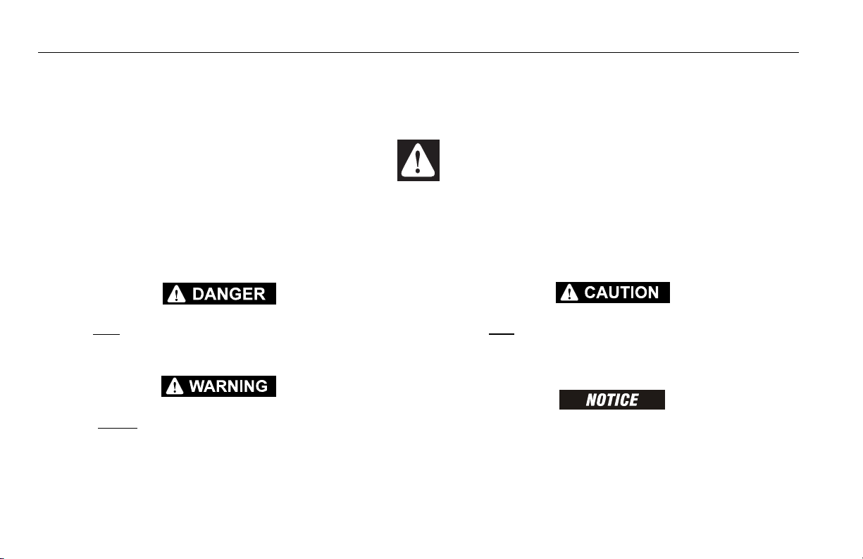
SAFETY ALERT SYMBOLS AND SAFETY SIGNAL WORDS
This is the Safety Alert Symbol. It is used to alert you to the potential personal
injury hazards. Obey all safety messages that follow this symbol to avoid possible
injury or death
INDICATES AN IMMINENTLY HAZARDOUS SITUATION. IF NOT
AVOIDED, WILL RESULT IN SERIOUS INJURY OR DEATH. THIS DECAL
WILL HAVE A RED BACKGROUND.
INDICATES A POTENTIALLY HAZARDOUS SITUATION. IF NOT
AVOIDED, COULD
DECAL WILL HAVE AN ORANGE BACKGROUND.
RESULT IN SERIOUS INJURY OR DEATH. THIS
INDICATES A POTENTIALLY HAZARDOUS SITUATION. IF NOT
AVOIDED, MAY RESULT IN MINOR OR MODERATE INJURY. IT MAY
ALSO ALERT AGAINST UNSAFE PRACTICES. THIS DECAL WILL HAVE A
YELLOW BACKGROUND.
INDICATES INFORMATION OR A COMPANY POLICY THAT RELATES
DIRECTLY OR INDIRECTLY TO THE SAFETY OF PERSONNEL OR PROTECTION OF PROPERTY.
b – JLG Lift – 3121156
Page 5

THIS PRODUCT MUST COMPLY WITH ALL SAFETY RELATED BULLETINS. CONTACT JLG INDUSTRIES, INC. OR THE LOCAL AUTHORIZED
JLG REPRESENTATIVE FOR INFORMATION REGARDING SAFETYRELATED BULLETINS WHICH MAY HAVE BEEN ISSUED FOR THIS
PRODUCT.
For:
• Accident Reporting
• Product Safety Publications
• Current Owner Updates
• Questions Regarding
Product Safety
FOREWORD
• Standards and Regulations
Compliance Information
• Questions Regarding Special Product Applications
• Questions Regarding Product Modifications
JLG INDUSTRIES, INC. SENDS SAFETY RELATED BULLETINS TO THE
OWNER OF RECORD OF THIS MACHINE. CONTACT JLG INDUSTRIES,
INC. TO ENSURE THAT THE CURRENT OWNER RECORDS ARE
UPDATED AND ACCURATE.
JLG INDUSTRIES, INC. MUST BE NOTIFIED IMMEDIATELY IN ALL
INSTANCES WHERE JLG PRODUCTS HAVE BEEN INVOLVED IN AN
ACCIDENT INVOLVING BODILY INJURY OR DEATH OF PERSONNEL OR
WHEN SUBSTANTIAL DAMAGE HAS OCCURRED TO PERSONAL PROPERTY OR THE JLG PRODUCT.
Contact:
Product Safety and Reliability Department
JLG Industries, Inc.
13224 Fountainhead Plaza
Hagerstown, MD 21742
USA
or Your Local JLG Office
(See addresses on inside of manual cover)
In USA:
Toll Free: 877-JLG-SAFE (877-554-7233)
Outside USA:
3121156 – JLG Lift – c
Phone: 240-420-2661
Fax: 301-745-3713
E-mail: ProductSafety@JLG.com
Page 6

FOREWORD
REVISION LOG
Original Issue - October 28, 2003
Revised - May 4, 2005
Revised - July 18, 2006
Revised - September 13, 2006
Revised - July 30, 2009
Revised - August 19, 2009
Revised - December 1, 2009
Revised - April 3, 2012
Revised - May 4, 2012
d – JLG Lift – 3121156
Page 7

TABLE OF CONTENTS
SECTION - PARAGRAPH, SUBJECT PAGE SECTION - PARAGRAPH, SUBJECT PAGE
SECTION - 1 - SAFETY PRECAUTIONS
1.1 GENERAL . . . . . . . . . . . . . . . . . . . . . . . . . . . . . . . . .1-1
1.2 PRE-OPERATION . . . . . . . . . . . . . . . . . . . . . . . . . . .1-1
Operator Training and Knowledge . . . . . . . . . . . 1-1
Workplace Inspection. . . . . . . . . . . . . . . . . . . . . 1-2
Machine Inspection . . . . . . . . . . . . . . . . . . . . . . 1-2
1.3 OPERATION . . . . . . . . . . . . . . . . . . . . . . . . . . . . . . .1-3
General . . . . . . . . . . . . . . . . . . . . . . . . . . . . . . . . 1-3
Trip and Fall Hazards . . . . . . . . . . . . . . . . . . . . . 1-3
Electrocution Hazards . . . . . . . . . . . . . . . . . . . . 1-4
Tipping Hazards . . . . . . . . . . . . . . . . . . . . . . . . . 1-6
Crushing and Collision Hazards. . . . . . . . . . . . . 1-7
1.4 TOWING, LIFTING, AND HAULING . . . . . . . . . . . . .1-8
1.5 ADDITIONAL HAZARDS / SAFETY . . . . . . . . . . . . .1-9
SECTION - 2 - USER RESPONSIBILITIES, MACHINE PREPARATION, AND INSPECTION
2.1 PERSONNEL TRAINING . . . . . . . . . . . . . . . . . . . . .2-1
Operator Training . . . . . . . . . . . . . . . . . . . . . . . . 2-1
Training Supervision. . . . . . . . . . . . . . . . . . . . . . 2-1
Operator Responsibility . . . . . . . . . . . . . . . . . . . 2-1
2.2 PREPARATION, INSPECTION, AND
MAINTENANCE . . . . . . . . . . . . . . . . . . . . . . . . . . .2-2
Pre-Start Inspection . . . . . . . . . . . . . . . . . . . . . . 2-4
Daily Functional Check. . . . . . . . . . . . . . . . . . . . 2-5
General . . . . . . . . . . . . . . . . . . . . . . . . . . . . . . . 2-12
SECTION - 3 - MACHINE CONTROLS AND INDICATORS
3.1 GENERAL . . . . . . . . . . . . . . . . . . . . . . . . . . . . . . . . 3-1
3.2 CONTROLS AND INDICATORS . . . . . . . . . . . . . . . 3-1
Ground Control Station . . . . . . . . . . . . . . . . . . . . 3-1
Ground Control Indictor Panel . . . . . . . . . . . . . . 3-6
Platform Control Station . . . . . . . . . . . . . . . . . . . 3-9
Platform Control Indicator Panel . . . . . . . . . . . . 3-16
SECTION - 4 - MACHINE OPERATION
4.1 DESCRIPTION. . . . . . . . . . . . . . . . . . . . . . . . . . . . . 4-1
4.2 ENGINE OPERATION . . . . . . . . . . . . . . . . . . . . . . . 4-2
Starting Procedure . . . . . . . . . . . . . . . . . . . . . . . 4-2
Shutdown Procedure . . . . . . . . . . . . . . . . . . . . . 4-3
4.3 TRAVELING (DRIVING) . . . . . . . . . . . . . . . . . . . . . . 4-3
Traveling Forward or Reverse . . . . . . . . . . . . . . . 4-6
Stability . . . . . . . . . . . . . . . . . . . . . . . . . . . . . . . . 4-8
4.4 STEERING. . . . . . . . . . . . . . . . . . . . . . . . . . . . . . . 4-10
4.5 PARKING AND STOWING . . . . . . . . . . . . . . . . . . 4-10
4.6 PLATFORM . . . . . . . . . . . . . . . . . . . . . . . . . . . . . . 4-10
Platform Level Adjustment . . . . . . . . . . . . . . . . 4-10
Platform Rotation. . . . . . . . . . . . . . . . . . . . . . . . 4-10
4.7 BOOM . . . . . . . . . . . . . . . . . . . . . . . . . . . . . . . . . . 4-11
Swinging the Boom . . . . . . . . . . . . . . . . . . . . . . 4-11
3121156 – JLG Lift – i
Page 8

TABLE OF CONTENTS
SECTION - PARAGRAPH, SUBJECT PAGE SECTION - PARAGRAPH, SUBJECT PAGE
Raising and Lowering the Main Boom . . . . . . 4-11
Telescoping the Main Boom . . . . . . . . . . . . . . 4-12
4.8 SHUT DOWN AND PARK . . . . . . . . . . . . . . . . . . . 4-12
4.9 TIE DOWN AND LIFTING. . . . . . . . . . . . . . . . . . . . 4-12
Tie Down . . . . . . . . . . . . . . . . . . . . . . . . . . . . . 4-12
Lifting . . . . . . . . . . . . . . . . . . . . . . . . . . . . . . . . 4-12
4.10 AUXILIARY POWER . . . . . . . . . . . . . . . . . . . . . . . . 4-13
4.11 HYDRAULIC TOOL CIRCUIT INSTRUCTIONS
(OPTIONAL). . . . . . . . . . . . . . . . . . . . . . . . . . . . . 4-16
Tool Circuit . . . . . . . . . . . . . . . . . . . . . . . . . . . . 4-16
4.12 PLACARDS AND DECALS. . . . . . . . . . . . . . . . . . . 4-18
SECTION - 5 - EMERGENCY PROCEDURES
5.1 GENERAL . . . . . . . . . . . . . . . . . . . . . . . . . . . . . . . . 5-1
5.2 INCIDENT NOTIFICATION. . . . . . . . . . . . . . . . . . . . 5-1
5.3 EMERGENCY OPERATION. . . . . . . . . . . . . . . . . . . 5-2
Operator Unable to Control Machine . . . . . . . . 5-2
Platform or Boom Caught Overhead. . . . . . . . . 5-2
SECTION - 6 - GENERAL SPECIFICATIONS & OPERATOR
MAINTENANCE
6.1 INTRODUCTION . . . . . . . . . . . . . . . . . . . . . . . . . . . 6-1
6.2 OPERATING SPECIFICATIONS . . . . . . . . . . . . . . . 6-1
Capacities . . . . . . . . . . . . . . . . . . . . . . . . . . . . . 6-3
Engine Data . . . . . . . . . . . . . . . . . . . . . . . . . . . . 6-3
Hydraulic Oil . . . . . . . . . . . . . . . . . . . . . . . . . . . . 6-4
Major Component Weights. . . . . . . . . . . . . . . . . 6-7
Serial Number Locations . . . . . . . . . . . . . . . . . . 6-8
6.3 OPERATOR MAINTENANCE . . . . . . . . . . . . . . . . .6-14
6.4 SUPPLEMENTAL INFORMATION . . . . . . . . . . . . .6-19
SECTION - 7 - INSPECTION AND REPAIR LOG
ii – JLG Lift – 3121156
Page 9

TABLE OF CONTENTS
SECTION - PARAGRAPH, SUBJECT PAGE SECTION - PARAGRAPH, SUBJECT PAGE
LIST OF FIGURES
2-1. Drive Function Operating Range Diagrams -
Sheet 1 of 3 . . . . . . . . . . . . . . . . . . . . . . . . . . . . . .2-8
2-2. Drive Function Operating Range Diagrams -
Sheet 2 of 3 . . . . . . . . . . . . . . . . . . . . . . . . . . . . . .2-9
2-3. Drive Function Operating Range Diagrams -
Sheet 3 of 3 . . . . . . . . . . . . . . . . . . . . . . . . . . . . .2-10
2-4. Daily Walk-Around Inspection Diagram. . . . . . . . .2-11
2-5. Daily Walkaround Inspection Points -
Sheet 1 of 3 . . . . . . . . . . . . . . . . . . . . . . . . . . . . .2-12
2-6. Daily Walkaround Inspection Points -
Sheet 2 of 3 . . . . . . . . . . . . . . . . . . . . . . . . . . . . .2-13
2-7. Daily Walkaround Inspection Points -
Sheet 3 of 3 . . . . . . . . . . . . . . . . . . . . . . . . . . . . .2-14
3-1. Ground Control Station - 600SC . . . . . . . . . . . . . . .3-2
3-2. Ground Control Station - 660SJC . . . . . . . . . . . . . .3-3
3-3. Ground Control Indicator Panel - Sheet 1 of 2 . . . .3-7
3-4. Ground Control Indicator Panel - Sheet 2 of 2 . . . .3-8
3-5. Platform Control Console. . . . . . . . . . . . . . . . . . . .3-11
3-6. Platform Control Console w/Drive Orientation. . . .3-12
3-7. Platform Control Indicator Panel . . . . . . . . . . . . . .3-17
3-8. Platform Control Indicator Panel w/Drive
Orientation . . . . . . . . . . . . . . . . . . . . . . . . . . . . . .3-17
4-1. Grades and Sideslopes . . . . . . . . . . . . . . . . . . . . . .4-4
4-2. Machine Motion Hazard . . . . . . . . . . . . . . . . . . . . . .4-5
4-3. Position of Least Backward Stability . . . . . . . . . . . 4-8
4-4. Position of Least Forward Stability . . . . . . . . . . . . . 4-9
4-5. Machine Tie Down . . . . . . . . . . . . . . . . . . . . . . . . 4-14
4-6. Lifting Chart. . . . . . . . . . . . . . . . . . . . . . . . . . . . . . 4-15
4-7. Decal Installation - Sheet 1 of 10 . . . . . . . . . . . . . 4-19
4-8. Decal Installation - Sheet 2 of 10 . . . . . . . . . . . . . 4-20
4-9. Decal Installation - Sheet 3 of 10 . . . . . . . . . . . . . 4-21
4-10. Decal Installation - Sheet 4 of 10 . . . . . . . . . . . . . 4-22
4-11. Decal Installation - Sheet 5 of 10 . . . . . . . . . . . . . 4-23
4-12. Decal Installation - Sheet 6 of 10 . . . . . . . . . . . . . 4-24
4-13. Decal Installation - Sheet 7 of 10 . . . . . . . . . . . . . 4-25
4-14. Decal Installation - Sheet 8 of 10 . . . . . . . . . . . . . 4-26
4-15. Decal Installation - Sheet 9 of 10 . . . . . . . . . . . . . 4-27
4-16. Decal Installation - Sheet 10 of 10 . . . . . . . . . . . . 4-28
6-1. Serial Number Locations . . . . . . . . . . . . . . . . . . . . 6-8
6-2. Engine Operating Temperature Specifications -
Deutz - Sheet 1 of 2. . . . . . . . . . . . . . . . . . . . . . . . 6-9
6-3. Engine Operating Temperature Specifications -
Deutz - Sheet 2 of 2. . . . . . . . . . . . . . . . . . . . . . . 6-10
6-4. Engine Operating Temperature Specifications -
Caterpillar - Sheet 1 of 2 . . . . . . . . . . . . . . . . . . . 6-11
6-5. Engine Operating Temperature Specifications -
Caterpillar - Sheet 2 of 2 . . . . . . . . . . . . . . . . . . . 6-12
6-6. Operator Maintenance and Lubrication Diagram. 6-13
3121156 – JLG Lift – iii
Page 10

TABLE OF CONTENTS
SECTION - PARAGRAPH, SUBJECT PAGE SECTION - PARAGRAPH, SUBJECT PAGE
LIST OF TABLES
1-1 Minimum Approach Distances (M.A.D.) . . . . . . . . . 1-5
1-2 Beaufort Scale (For Reference Only) . . . . . . . . . . 1-10
2-1 Inspection and Maintenance Table . . . . . . . . . . . . . 2-3
4-1 600SC Decal Legend - Prior to S/N 0300148842 . 4-29
4-2 600SC Decal Legend - S/N 0300148842 to
Present . . . . . . . . . . . . . . . . . . . . . . . . . . . . . . . . . . 4-31
4-3 660SJC Decal Legend - Prior to
S/N 0300148842 . . . . . . . . . . . . . . . . . . . . . . . . . .4-35
4-4 660SJC Decal Legend - S/N 0300148842 to
Present . . . . . . . . . . . . . . . . . . . . . . . . . . . . . . . . . . 4-37
6-1 Operating Specifications - Prior to
S/N 0300148842 . . . . . . . . . . . . . . . . . . . . . . . . . . .6-1
6-2 Operating Specifications - S/N 0300148842
to Present. . . . . . . . . . . . . . . . . . . . . . . . . . . . . . . . . 6-2
6-3 Capacities . . . . . . . . . . . . . . . . . . . . . . . . . . . . . . . . 6-3
6-4 Deutz F4M1011F/F4M2011 Specifications . . . . . . . 6-3
6-5 Caterpillar 3044C/3.4 . . . . . . . . . . . . . . . . . . . . . . . . 6-4
6-6 Hydraulic Oil . . . . . . . . . . . . . . . . . . . . . . . . . . . . . . 6-4
6-7 Mobilfluid 424 Specs . . . . . . . . . . . . . . . . . . . . . . . .6-5
6-8 Mobil DTE 13M Specs . . . . . . . . . . . . . . . . . . . . . . . 6-5
6-9 Exxon Univis HVI 26 Specs . . . . . . . . . . . . . . . . . . . 6-6
6-10 Quintolubric 888-46 . . . . . . . . . . . . . . . . . . . . . . . . .6-6
6-11 Major Component Weights . . . . . . . . . . . . . . . . . . . 6-7
6-12 Lubrication Specifications . . . . . . . . . . . . . . . . . . . 6-14
7-1 Inspection and Repair Log . . . . . . . . . . . . . . . . . . . 7-1
iv – JLG Lift – 3121156
Page 11

SECTION 1 - SAFETY PRECAUTIONS
SECTION 1. SAFETY PRECAUTIONS
1.1 GENERAL
This section outlines the necessary precautions for proper
and safe machine operation and maintenance. For proper
machine use, it is mandatory that a daily routine is established based on the content of this manual. A maintenance
program, using the information provided in this manual and
the Service and Maintenance Manual, must also be established by a qualified person and followed to ensure the
machine is safe to operate.
The owner/user/operator/lessor/lessee of the machine
should not operate the machine until this manual has been
read, training is accomplished, and operation of the machine
has been completed under the supervision of an experienced and qualified operator.
If there are any questions with regard to safety, training,
inspection, maintenance, application, and operation, please
contact JLG Industries, Inc. (“JLG”).
FAILURE TO COMPLY WITH THE SAFETY PRECAUTIONS LISTED IN
THIS MANUAL COULD RESULT IN MACHINE DAMAGE, PROPERTY DAMAGE, PERSONAL INJURY OR DEATH.
1.2 PRE-OPERATION
Operator Training and Knowledge
• Read and understand this manual before operating the
machine.
• Do not operate this machine until complete training is performed by authorized persons.
• Only authorized and qualified personnel can operate the
machine.
3121156 – JLG Lift – 1-1
Page 12

SECTION 1 - SAFETY PRECAUTIONS
• Read, understand, and obey all DANGERS, WARNINGS,
CAUTIONS, and operating instructions on the machine
and in this manual.
• Use the machine in a manner which is within the scope of
its intended application set by JLG.
• All operating personnel must be familiar with the emergency controls and emergency operation of the machine
as specified in this manual.
• Read, understand, and obey all applicable employer,
local, and governmental regulations as they pertain to
operation of the machine.
Workplace Inspection
• The operator is to take safety measures to avoid all hazards in the work area prior to machine operation.
• Do not operate or raise the platform while on trucks, trailers, railway cars, floating vessels, scaffolds or other equipment unless approved in writing by JLG.
• Do not operate the machine in hazardous environments
unless approved for that purpose by JLG.
• Be sure that the ground conditions are able to support the
maximum load shown on the decals located on the
machine.
Machine Inspection
• Before machine operation, perform inspections and functional checks. Refer to Section 2 of this manual for
detailed instructions.
• Do not operate this machine until it has been serviced and
maintained according to requirements specified in the
Service and Maintenance Manual.
• Be sure the footswitch and all other safety devices are
operating properly. Modification of these devices is a
safety violation.
MODIFICATION OR ALTERATION OF AN AERIAL WORK PLATFORM
SHALL BE MADE ONLY WITH WRITTEN PERMISSION FROM THE MANUFACTURER
• Do not operate any machine on which safety or instruction
placards or decals are missing or illegible.
• Avoid any buildup of debris on the platform floor. Keep
mud, oil, grease, and other slippery substances from footwear and platform floor.
1-2 – JLG Lift – 3121156
Page 13
SECTION 1 - SAFETY PRECAUTIONS
1.3 OPERATION
General
• Do not use the machine for any purpose other than positioning personnel, their tools, and equipment.
• Never operate a machine that is not working properly. If a
malfunctions occurs, shut down the machine.
• Never slam a control switch or lever through neutral to an
opposite direction. Always return switch to neutral and
stop before moving the switch to the next function. Operate controls with slow and even pressure.
• Hydraulic cylinders should never be left fully extended or
fully retracted before shutdown or for long periods of time.
• Do not allow personnel to tamper with or operate the
machine from the ground with personnel in the platform,
except in an emergency.
• Do not carry materials directly on platform railing. Contact
JLG for approved material handling accessories.
• When two or more persons are in the platform, the operator shall be responsible for all machine operations.
• Always ensure that power tools are properly stowed and
never left hanging by their cord from the platform work
area.
• Supplies or tools which extend outside the platform are
prohibited unless approved by JLG.
• When driving, always position boom over rear axle in line
with the direction of travel. Remember, if boom is over the
front axle, steer and drive functions will be reversed.
• Do not assist a stuck or disabled machine by pushing,
pulling, or by using boom functions. Only pull the unit
from the tie-down lugs on the chassis.
• Do not place boom or platform against any structure to
steady the platform or to support the structure.
• Stow boom and shut off all power before leaving machine.
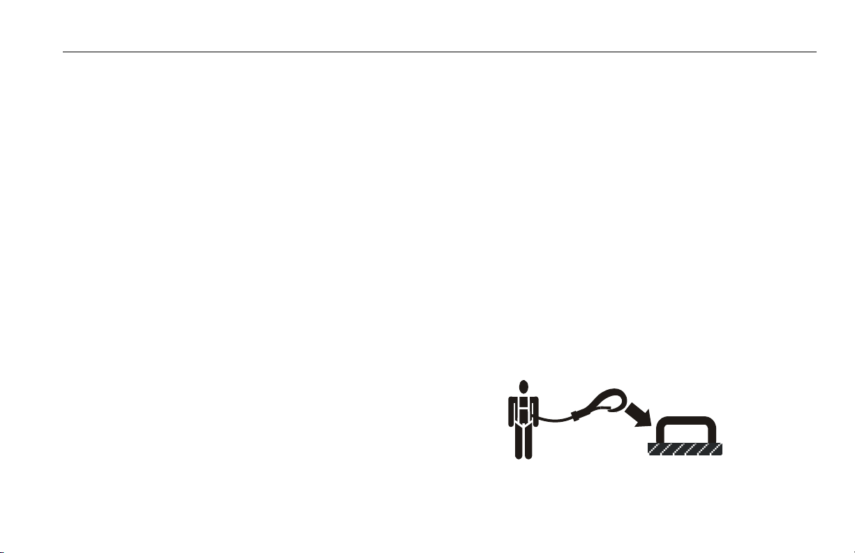
Trip and Fall Hazards
During operation, occupants in the platform must wear a full
body harness with a lanyard attached to an authorized lanyard anchorage point. Attach only one (1) lanyard per lanyard anchorage point.
3121156 – JLG Lift – 1-3
Page 14
SECTION 1 - SAFETY PRECAUTIONS
• Before operating the machine, make sure all gates are
closed and fastened in their proper position.
• Keep both feet firmly positioned on the platform floor at all
times. Never use ladders, boxes, steps, planks, or similar
items on platform to provide additional reach.
• Never use the boom assembly to enter or leave the platform.
• Use extreme caution when entering or leaving platform.
Be sure that the boom is fully lowered. It may be necessary to telescope out to position the platform closer to the
ground for entry/exit. Face the machine, maintain “three
point contact” with the machine, using two hands and one
foot or two feet and one hand during entry and exit.
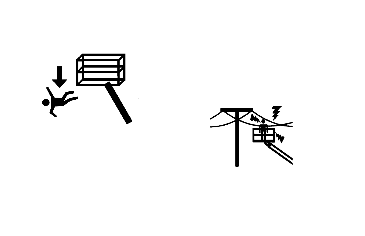
Electrocution Hazards
• This machine is not insulated and does not provide protection from contact or proximity to electrical current.
1-4 – JLG Lift – 3121156
Page 15
SECTION 1 - SAFETY PRECAUTIONS
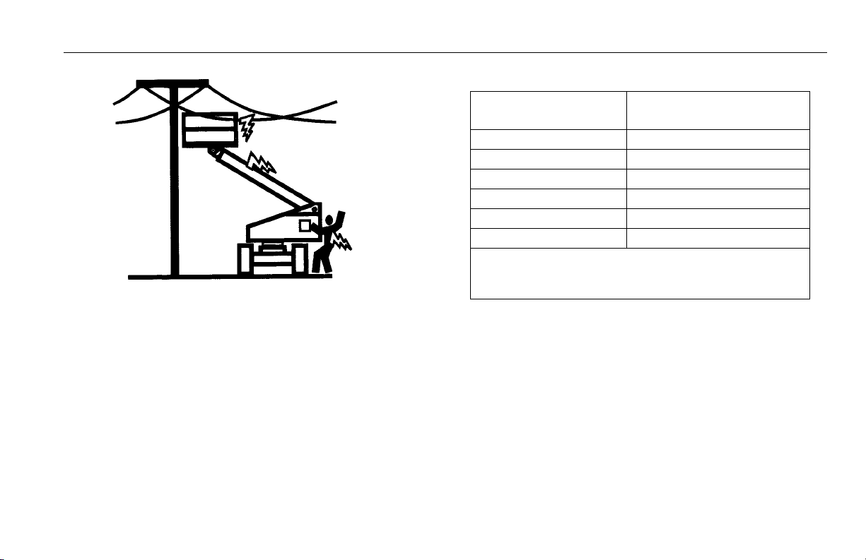
Table 1-1. Minimum Approach Distances (M.A.D.)
• Maintain distance from electrical lines, apparatus, or any
energized (exposed or insulated) parts according to the
Minimum Approach Distance (MAD) as shown in Table 1-
1.
• Allow for machine movement and electrical line swaying.
Voltage Range
(Phase to Phase)
0 to 50 KV 10 (3)
Over 50KV to 200 KV 15 (5)
Over 200 KV to 350 KV 20 (6)
Over 350 KV to 500 KV 25 (8)
Over 500 KV to 750 KV 35 (11)
Over 750 KV to 1000 KV 45 (14)
NOTE: This requirement shall apply except where
employer, local or governmental regulations
are more stringent.
• Maintain a clearance of at least 10 ft. (3m) between any part
of the machine and its occupants, their tools, and their
equipment from any electrical line or apparatus carrying up
to 50,000 volts. One foot additional clearance is required for
every additional 30,000 volts or less.
MINIMUM APPROACH DISTANCE
in Feet (Meters)
3121156 – JLG Lift – 1-5
Page 16
SECTION 1 - SAFETY PRECAUTIONS
• The minimum approach distance may be reduced if insulating barriers are installed to prevent contact, and the barriers
are rated for the voltage of the line being guarded. These
barriers shall not be part of (or attached to) the machine. The
minimum approach distance shall be reduced to a distance
within the designed working dimensions of the insulating
barrier. This determination shall be made by a qualified person in accordance with the employer, local, or governmental
requirements for work practices near energized equipment
DO NOT MANEUVER MACHINE OR PERSONNEL INSIDE PROHIBITED
ZONE (MAD). ASSUME ALL ELECTRICAL PARTS AND WIRING ARE
ENERGIZED UNLESS KNOWN OTHERWISE.
Tipping Hazards
• The user should be familiar with the surface before driving. Do not exceed the allowable sideslope and grade
while driving.
1-6 – JLG Lift – 3121156
Page 17
SECTION 1 - SAFETY PRECAUTIONS
• Do not elevate platform or drive with platform elevated
while on a sloping, uneven, or soft surface.
• Before driving on floors, bridges, trucks, and other surfaces, check allowable capacity of the surfaces.
• Never exceed the maximum platform capacity. Distribute
loads evenly on platform floor.
• Do not raise the platform or drive from an elevated position unless the machine is on firm, level and smooth surfaces.
• Keep the chassis of the machine at least 2 ft. (0.6m) from
holes, bumps, drop-offs, obstructions, debris, concealed
holes, and other potential hazards on the floor/surface.
• Do not push or pull any object with the boom.
• Never attempt to use the machine as a crane. Do not tieoff machine to any adjacent structure.
• Do not operate the machine when wind conditions exceed
28 mph (12.5 m/s). Refer to Table 1-2, Beaufort Scale (For
Reference Only).
• Do not increase the surface area of the platform or the
load. Increase of the area exposed to the wind will
decrease stability.
• Do not increase the platform size with unauthorized deck
extensions or attachments.
• If boom assembly or platform is in a position that one or
more wheels are off the ground, all persons must be
removed before attempting to stabilize the machine. Use
cranes, forklift trucks, or other appropriate equipment to
stabilize machine.
Crushing and Collision Hazards
• Approved head gear must be worn by all operating and
ground personnel.
• Check work area for clearances overhead, on sides, and
bottom of platform when lifting or lowering platform, and
driving.
• During operation, keep all body parts inside platform railing.
3121156 – JLG Lift – 1-7
Page 18

SECTION 1 - SAFETY PRECAUTIONS
• Use the boom functions, not the drive function, to position
the platform close to obstacles.
• Always post a lookout when driving in areas where vision
is obstructed.
• Keep non-operating personnel at least 6 ft. (1.8m) away
from machine during all driving and swing operations.
• Limit travel speed according to conditions of ground surface, congestion, visibility, slope, location of personnel,
and other factors which may cause collision or injury to
personnel.
• Be aware of stopping distances in all drive speeds. When
driving in high speed, switch to low speed before stopping. Travel grades in low speed only.
• Do not use high speed drive in restricted or close quarters
or when driving in reverse.
• Exercise extreme caution at all times to prevent obstacles
from striking or interfering with operating controls and persons in the platform.
• Be sure that operators of other overhead and floor level
machines are aware of the aerial work platform’s presence. Disconnect power to overhead cranes.
• Warn personnel not to work, stand, or walk under a raised
boom or platform. Position barricades on floor if necessary.
1.4 TOWING, LIFTING, AND HAULING
• Never allow personnel in platform while towing, lifting, or
hauling.
• This machine should not be towed, except in the event of
emergency, malfunction, power failure, or loading/unloading. Refer to the Emergency Procedures section of this
manual for emergency towing procedures.
• Ensure boom is in the stowed position and the turntable
locked prior to towing, lifting or hauling. The platform must
be completely empty of tools.
• When lifting machine, lift only at designated areas of the
machine. Lift the unit with equipment of adequate capacity.
• Refer to the Machine Operation section of this manual for
lifting information.
1-8 – JLG Lift – 3121156
Page 19

SECTION 1 - SAFETY PRECAUTIONS
1.5 ADDITIONAL HAZARDS / SAFETY
• Do not use machine as a ground for welding.
• When performing welding or metal cutting operations,
precautions must be taken to protect the chassis from
direct exposure to weld and metal cutting spatter.
• Do not refuel the machine with the engine running.
• Battery fluid is highly corrosive. Avoid contact with skin
and clothing at all times.
• Charge batteries only in a well ventilated area.
3121156 – JLG Lift – 1-9
Page 20

SECTION 1 - SAFETY PRECAUTIONS
DO NOT OPERATE THE MACHINE WHEN WIND CONDITIONS EXCEED 28
MPH (12.5 M/S).
Table 1-2. Beaufort Scale (For Reference Only)
Beaufort
Number
0 0 0-0.2 Calm Calm. Smoke rises vertically
1 1-3 0.3-1.5 Light air Wind motion visible in smoke
2 4-7 1.6-3.3 Light breeze Wind felt on exposed skin. Leaves r ustle
3 8-12 3.4-5.4 Gentle breeze Leaves and smaller twigs in constant motion
4 13-18 5.5-7.9 Moderate breeze Dust and loose paper raised. Small branches begin to move.
5 19-24 8.0-10.7 Fresh breeze Smaller trees sway.
6 25-31 10.8-13.8 Strong breeze Large branches in motion. Whistling heard in overhead wires.
7 32-38 13.9-17.1 Near Gale/Moderate Gale Whole trees in motion. Effor t needed to walk against the wind.
8 39-46 17.2-20.7 Fresh Gale Twigs broken from trees. Cars veer on road.
9 47-54 20.8-24.4 Strong Gale Light structure damage.
Wind Speed
mph m/s
Description Land Conditions
Umbrella use becomes difficult.
1-10 – JLG Lift – 3121156
Page 21

SECTION 2 - USER RESPONSIBILITIES, MACHINE PREPARATION, AND INSPECTION
SECTION 2. USER RESPONSIBILITIES, MACHINE PREPARATION, AND INSPECTION
2.1 PERSONNEL TRAINING
The aerial platform is a personnel handling device; so it is
necessary that it be operated and maintained only by trained
personnel.
Persons under the influence of drugs or alcohol or who are
subject to seizures, dizziness or loss of physical control must
not operate this machine.
Operator Training
Operator training must cover:
1. Use and limitations of the controls in the platform and at
the ground, emergency controls and safety systems.
2. Control labels, instructions, and warnings on the
machine.
3. Rules of the employer and government regulations.
4. Use of approved fall protection device.
5. Enough knowledge of the mechanical operation of the
machine to recognize a malfunction or potential malfunction.
6. The safest means to operate the machine where over-
head obstructions, other moving equipment, and obstacles, depressions, holes, drop-offs.
7. Means to avoid the hazards of unprotected electrical
conductors.
8. Specific job requirements or machine application.
Training Supervision
Training must be done under the supervision of a qualified
person in an open area free of obstructions until the trainee
has developed the ability to safely control and operate the
machine.
Operator Responsibility
The operator must be instructed that he/she has the responsibility and authority to shut down the machine in case of a
malfunction or other unsafe condition of either the machine
or the job site.
3121156 – JLG Lift – 2-1
Page 22

SECTION 2 - USER RESPONSIBILITIES, MACHINE PREPARATION, AND INSPECTION
2.2 PREPARATION, INSPECTION, AND MAINTENANCE
The following table covers the periodic machine inspections
and maintenance required by JLG Industries, Inc. Consult
local regulations for further requirements for aerial work platforms. The frequency of inspections and maintenance must
be increased as necessary when the machine is used in a
harsh or hostile environment, if the machine is used with
increased frequency, or if the machine is used in a severe
manner.
JLG INDUSTRIES, INC. RECOGNIZES A FACTORY-TRAINED SERVICE
TECHNICIAN AS A PERSON WHO HAS SUCCESSFULLY COMPLETED
THE JLG SERVICE TRAINING SCHOOL FOR THE SPECIFIC JLG PRODUCT
MODEL.
2-2 – JLG Lift – 3121156
Page 23

SECTION 2 - USER RESPONSIBILITIES, MACHINE PREPARATION, AND INSPECTION
Table 2-1.Inspection and Maintenance Table
Type Frequency
Pre-Start Inspection Before using each day; or
whenever there’s an Operator change.
Pre-Delivery Inspection
(See Note)
Frequent Inspection
(See Note)
Annual Machine Inspection
(See Note)
Preventative Maintenance At intervals as specified in the Service and Main-
NOTE: Inspection forms are available from JLG. Use the Service and Maintenance Manual to perform inspections.
Before each sale, lease, or rental delivery. Owner, Dealer, or User Qualified JLG
In service for 3 months or 150 hours, whichever
comes first;
o r
Out of service for a period of more than 3 months;
o r
Purchased used.
Annually, no later than 13 months from the date
of prior inspection.
tenance Manual.
Primary
Responsibility
User or Operator User or Operator Operator and Safety Manual
Owner, Dealer, or User Qualified JLG
Owner, Dealer, or User Factory-Trained
Owner, Dealer, or User Qualified JLG
Service
Qualification
Mechanic
Mechanic
Service Technician
(Recommended)
Mechanic
Service and Maintenance
Manual and applicable JLG
inspection form
Service and Maintenance
Manual and applicable JLG
inspection form
Service and Maintenance
Manual and applicable JLG
inspection form
Service and Maintenance
Manual
Reference
3121156 – JLG Lift – 2-3
Page 24
SECTION 2 - USER RESPONSIBILITIES, MACHINE PREPARATION, AND INSPECTION
Parent Metal Crack Weld Crack
Pre-Start Inspection
The Pre-Start Inspection should include each of the following:
1. Cleanliness – Check all surfaces for leakage (oil, fuel,
or battery fluid) or foreign objects. Report any leakage to
the proper maintenance personnel.
2. Structure - Inspect the machine structure for dents,
damage, weld or parent metal cracks or other discrepancies.
3. Decals and Placards – Check all for cleanliness and
legibility. Make sure none of the decals and placards are
missing. Make sure all illegible decals and placards are
cleaned or replaced.
4. Operators and Safety Manuals – Make sure a copy of
the Operator and Safety Manual, AEM Safety Manual
(Domestic only), and ANSI Manual of Responsibilities
(Domestic only) is enclosed in the weather resistant
storage container.
5. “Walk-Around” Inspection – Refer to Figure 2-4., Fig-
ure 2-6. and Figure 2-7.
6. Battery – Charge as required.
7. Fuel (Combustion Engine Powered Machines) – Add the
proper fuel as necessary.
8. Engine Oil Supply - Ensure the engine oil level is at the
Full mark on the dipstick and the filler cap is secure.
9. Hydraulic Oil – Check the hydraulic oil level. Ensure
hydraulic oil is added as required.
10. Accessories/Attachments - Reference the Operator
and Safety Manual of each attachment or accessory
installed upon the machine for specific inspection, operation, and maintenance instructions.
11. Function Check – Once the “Walk-Around” Inspection
is complete, perform a functional check of all systems in
an area free of overhead and ground level obstructions.
Refer to Section 4 for more specific operating instructions.
2-4 – JLG Lift – 3121156
Page 25

SECTION 2 - USER RESPONSIBILITIES, MACHINE PREPARATION, AND INSPECTION
IF THE MACHINE DOES NOT OPERATE PROPERLY, TURN OFF THE
MACHINE IMMEDIATELY! REPORT THE PROBLEM TO THE PROPER
MAINTENANCE PERSONNEL. DO NOT OPERATE THE MACHINE UNTIL IT
IS DECLARED SAFE FOR OPERATION.
NOTE: Perform checks from ground controls first, then from plat-
form controls.
1. Operate machine from ground control.
NOTE: For adjustments see Service Manual, Limit Switch Adjust-
ments.
Daily Functional Check
A functional check of all systems should be performed, once
the walk-around inspection is complete, in an area free of
overhead and ground level obstructions. First, using the
ground controls, check all functions controlled by the ground
controls. Next, using the platform controls, check all functions controlled by the platform controls.
TO AVOID SERIOUS INJURY, DO NOT OPERATE MACHINE IF ANY CONTROL LEVERS OR TOGGLE SWITCHES CONTROLLING PLATFORM
MOVEMENTS DO NOT RETURN TO THE OFF OR NEUTRAL POSITION
WHEN RELEASED.
TO AVOID COLLISION AND INJURY IF PLATFORM DOES NOT STOP
WHEN A CONTROL SWITCH OR LEVER IS RELEASED, REMOVE FOOT
FROM FOOTSWITCH OR USE EMERGENCY STOP TO STOP THE
MACHINE.
2. Check elevation limit switch as follows:
While driving in high drive, elevate the boom to approximately 10 degrees. Drive should cut back to low speed.
The switch should reset when the boom is fully lowered.
3. Check capacity limit switch as follows:
a. Boom Length Switch.
Raise boom to horizontal. Telescope boom out until
500 lb. light comes on. Make sure the switch resets
and the 1000 lb. light comes back on when telescoping in.
b. Boom Angle Switch.
Telescope boom to full extension.
Lift boom up until 1000 lb. light comes on.
Lift boom down using auxiliary power until 500 lb.
3121156 – JLG Lift – 2-5
Page 26

SECTION 2 - USER RESPONSIBILITIES, MACHINE PREPARATION, AND INSPECTION
ANSI, ANSI Expor t, CSA, Japan 5°
CE, Australia 3°
light comes on. Boom angle must be approximately
45 to 50 degrees
Lift boom up until 1000 lb. light comes on. The
switch should reset when the boom angle is about
55 degrees to 64 degrees.
NOTE: If limit switch settings need to be changed, you will need
to recheck that the 500 lb. light comes on at 45 degrees to
50 degrees when lifting down.
4. Drive Disable Switch (Refer to Figure 2-2., Drive Func-
tion Operating Range Diagrams - Sheet 2 of 3).
a. Telescope the boom out over 40 ft. (12.2 m).
b. Manually tilt the tilt sensor.
c. Drive Disable Indicator Light should come on.
d. Retract the boom and elevate to at least 55°.
e. Manually tilt the tilt sensor.
f. The Drive Disable Indicator Light should come on
again.
5. Raise main boom, extend and retract telescope. Check
for delayed movement of fly section, indicating loose
cables.
NOTE: Turntable lock is on turntable facing platform. To disen-
gage lock, pull snap pin from lock pin, lift lock pin up to
unlock turntable. Return snap pin to lock pin to hold lock
pin in the disengaged position. Reverse procedure to
engage turntable lock.
6. Swing turntable to LEFT and RIGHT a minimum of 45
degrees. Check for smooth motion.
7. Check the chassis out of level indicator located on the
platform control console by driving, with the machine in
level position, up a suitable ramp of at least 5° slope.
Check the out of level indicator, with the machine on the
ramp. If the light does not illuminate, return the machine
to a level surface, shut down the machine, and contact a
qualified technician before resuming operation.
8. Check that platform automatic self-leveling system func-
tions properly during raising and lowering of the boom.
9. Check platform level adjustment system for proper oper-
ation.
10. Check platform rotator for smooth operation and assure
platform will rotate 90 degrees in both directions from
centerline of boom.
2-6 – JLG Lift – 3121156
Page 27

SECTION 2 - USER RESPONSIBILITIES, MACHINE PREPARATION, AND INSPECTION
11. Drive forward and reverse; check for proper operation.
12. Steer left and right; check for proper operation.
13. Raise and lower Articulating Jib Boom. Check for
smooth operation.
14. Footswitch.
FOOTSWITCH MUST BE ADJUSTED SO THAT FUNCTIONS WILL OPERATE WHEN PEDAL IS APP ROXIM ATELY AT ITS CEN TER OF TRAVEL. IF
SWITCH OPERATES WITHIN LAST 1/4" OF TRAVEL, TOP OR BOTTOM, IT
SHOULD BE ADJUSTED.
a. Activate hydraulic system. By depressing foot-
switch. Operate MAIN TELESCOPE and hold control. Remove foot from footswitch, motion should
stop. If it does not, shut down machine and contact
a certified JLG service technician.
b. With footswitch depressed, operate LIFT and hold
control. Remove foot from footswitch, motion
should stop. If it does not, shut down machine and
contact a certified JLG service technician.
c. With engine power shut down, depress the foot-
switch. Attempt to start engine. Engine should not
attempt to start when footswitch is depressed. If
starter engages or engine turns over, shut down
machine and contact a certified JLG service technician.
15. Auxiliary Power.
Operate each function control switch (e.g. TELE, LIFT
and SWING) to assure that they function in both directions using auxiliary power instead of engine power.
16. Ground Controls.
Place GROUND/PLATFORM SELECT switch to
GROUND. Start engine. Platform controls should not
operate.
3121156 – JLG Lift – 2-7
Page 28
SECTION 2 - USER RESPONSIBILITIES, MACHINE PREPARATION, AND INSPECTION
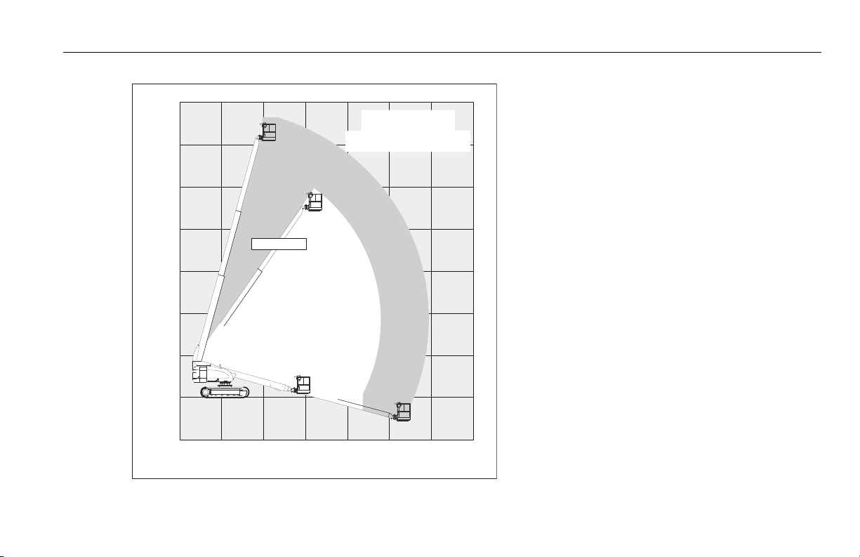
Figure 2-1. Drive Function Operating Range Diagrams - Sheet 1 of 3
NOTE: In the Transport Mode, High Drive
will be disabled above 10° elevation
or past 3 feet (1 m) of boom extension.
2-8 – JLG Lift – 3121156
Page 29
70ft.
21.34 m
60ft.
18.29 m
60ft.
18.29 m
50ft.
15.24 m
50ft.
15.24 m
40ft.
12.19 m
40ft.
12.19 m
30ft.
9.14 m
30ft.
9.14 m
20ft.
6.10 m
20ft.
6.10 m
10ft.
3.05 m
10ft.
3.05 m
0
10ft.
3.05 m
CHASSIS
TILTED> 1.8°
NO DRIVE IF
CHASSIS
TILTED> 1.8°
DRIVE CUTOUT
PER
PERSONALITY
SETTING
55 DEGREES
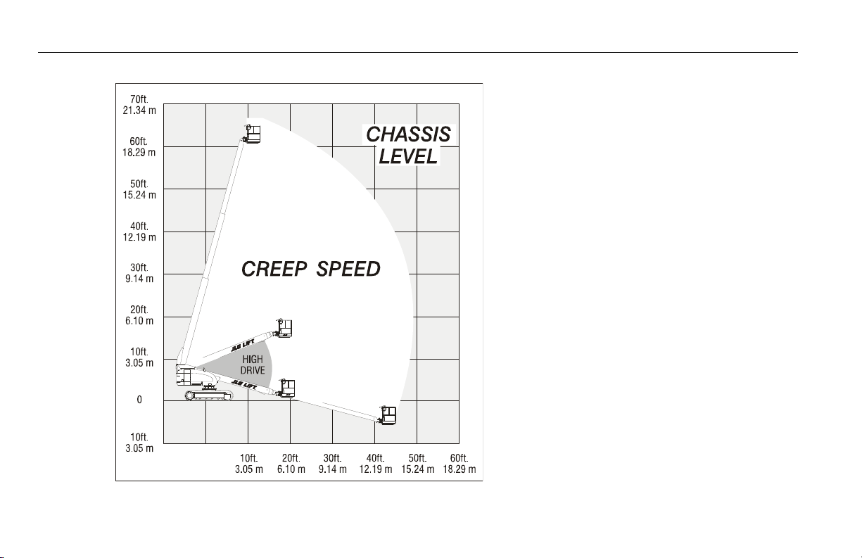
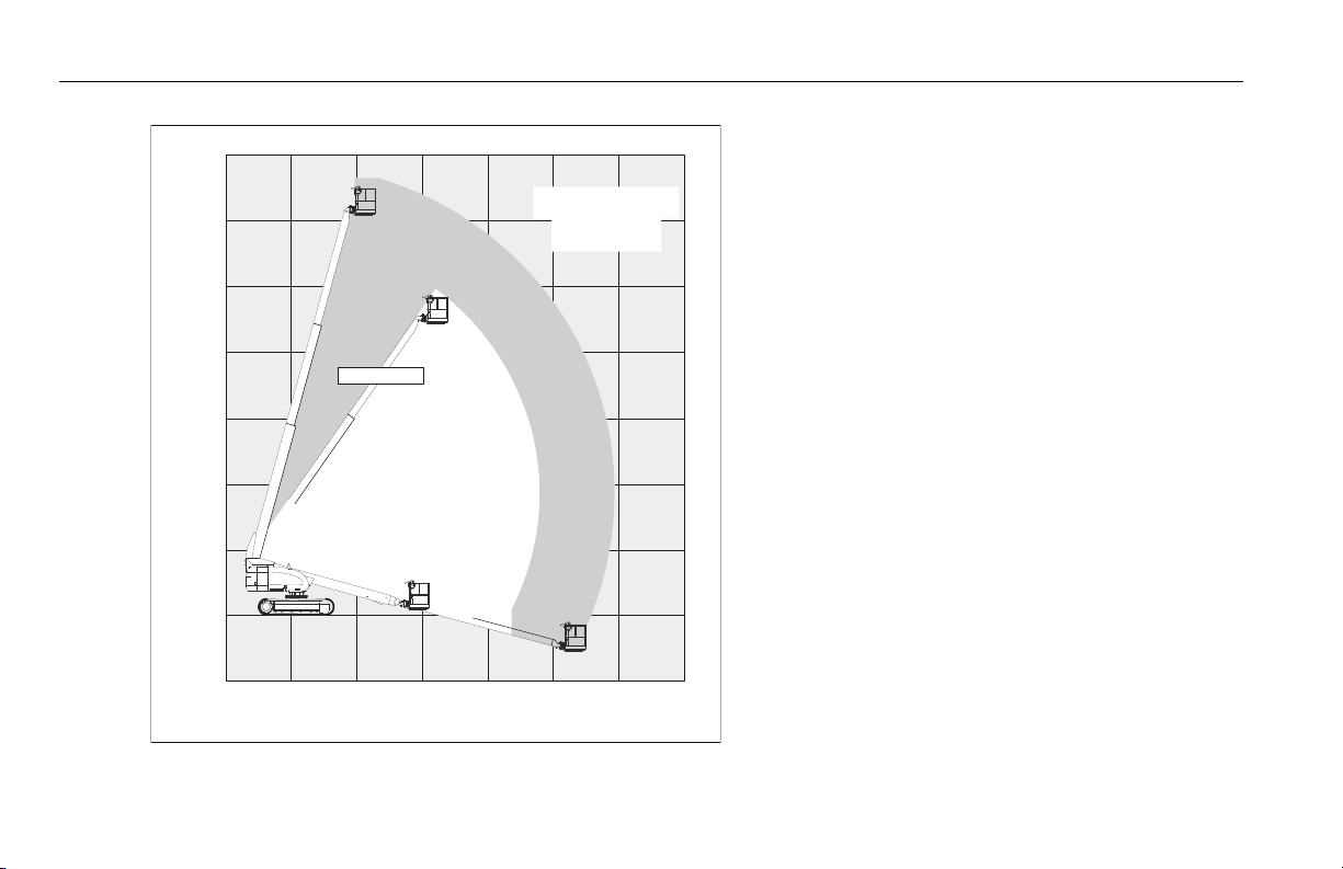
Figure 2-2. Drive Function Operating Range Diagrams - Sheet 2 of 3
NOTE: In the Transport Mode, High Drive will
be disabled above 10° elevation or
past 3 feet (1 m) of boom extension.
SECTION 2 - USER RESPONSIBILITIES, MACHINE PREPARATION, AND INSPECTION
3121156 – JLG Lift – 2-9
Page 30
SECTION 2 - USER RESPONSIBILITIES, MACHINE PREPARATION, AND INSPECTION
70ft.
21.34 m
60ft.
18.29 m
60ft.
18.29 m
50ft.
15.24 m
50ft.
15.24 m
40ft.
12.19 m
40ft.
12.19 m
30ft.
9.14 m
30ft.
9.14 m
20ft.
6.10 m
20ft.
6.10 m
10ft.
3.05 m
10ft.
3.05 m
0
10ft.
3.05 m
55 DEGREES
CHASSIS
TILTED
CREEP CUTOUTS
PER PERSONALITY
SETTING
CREEP IF
TILTED > 1.8°
CUTOUTS PER
PERSONALITY SETTING
Figure 2-3. Drive Function Operating Range Diagrams - Sheet 3 of 3
NOTE: In the Transport Mode, High Drive will
be disabled above 10° elevation or
past 3 feet (1 m) of boom extension.
2-10 – JLG Lift – 3121156
Page 31

SECTION 2 - USER RESPONSIBILITIES, MACHINE PREPARATION, AND INSPECTION
Figure 2-4. Daily Walk-Around Inspection Diagram
3121156 – JLG Lift – 2-11
Page 32

SECTION 2 - USER RESPONSIBILITIES, MACHINE PREPARATION, AND INSPECTION
General
Begin the "Walk-Around Inspection" at Item 1, as noted on
the diagram. Continue to the right (counterclockwise
viewed from top) checking each item in sequence for the
conditions listed in the following checklist.
TO AVOID POSSIBLE INJURY, BE SURE MACHINE POWER IS OFF.
DO NOT OPERATE MACHINE UNTIL ALL MALFUNCTIONS HAVE BEEN
CORRECTED.
INSPECTION NOTE: On all components, make sure there
are no loose or missing parts, that they are securely fastened, and no visible damage, leaks or excessive wear
exists in addition to any other criteria mentioned.
1. Platform Assembly and Gate - Footswitch works
properly, not modified, disabled or blocked. Latch,
stop, and hinges in working condition.
2. Platform Control Console - Switches and levers
return to neutral, decals/placards secure and legible,
control markings legible.
3. Rotator - See Inspection Note.
4. Rotator Motion Control Valve - See Inspection Note.
5. Articulating Jib Boom - See Inspection Note.
6. Dual Capacity Limit Switch, Transport Position
Limit Switch - Switches operate properly.
7. Power Track - See Inspection Note.
8. Turntable Bearing and Pinion - No evidence of loose
bolts or looseness between bearing and structure. See
Inspection Note.
9. Right Track - Properly secured plates, no loose or
missing track bolts, no dislocation of the track pins.
Proper tension. See Inspection Note.
10. Final Drive, Both Sides - See Inspection Note.
11. Turntable Lock - Operable; See Inspection Note.
12. Auxiliary Power Pump - See Inspection Note.
13. Bottom Rollers, Right Side - See Inspection Note.
14. Track Carrier Roller, Both Sides - See Inspection
Note.
Figure 2-5. Daily Walkaround Inspection Points - Sheet 1 of 3
2-12 – JLG Lift – 3121156
Page 33

SECTION 2 - USER RESPONSIBILITIES, MACHINE PREPARATION, AND INSPECTION
15. Swing Drive Motor and Brake - See Inspection Note.
16. Control Valve (Tank Compartment) - See Inspection
Note.
17. Hydraulic Oil Return Filter - Housing secure; See
Inspection Note.
18. Hydraulic Oil Supply - Recommended oil level sight
gauge. (Check level with cold oil, systems shut down,
machine in stowed position) Cap in place and secure.
19. Hydraulic Oil Breather - Element in place, not
clogged, no sign of overflow.
20. Door and Latches, Right Side - Hood door and
latches in working condition. See Inspection Note.
21. Ground Controls - Switches and levers return to neu-
tral, decals/placards secure and legible, control markings legible.
22. Right Tension Mechanism - See Inspection Note.
23. Fuel Supply - Fuel filler cap secure. Tank - See
Inspection Note.
24. Idler, Right Front - See Inspection Note.
25. Dual Capacity Limit Switch - Switch operates prop-
erly.
26. Left Track - Properly secured plates, no loose or miss-
ing track bolts, no dislocation of the track pins. Proper
tension. See Inspection Note.
27. Idler, Left Front - See Inspection Note.
28. Left Tension Mechanism - See Inspection Note.
29. Bottom Rollers, Left Side - See Inspection Note.
30. Battery - Proper electrolyte levels; cables tight, no vis-
ible damage or corrosion.
31. Door and Latches, Left Side - Hood door and latches
in working condition, see Inspection Note.
32. Engine Air Filter - See Inspection Note.; element
clean.
33. Engine Oil Supply - Full mark on dipstick; filler cap
secure.
Figure 2-6. Daily Walkaround Inspection Points - Sheet 2 of 3
3121156 – JLG Lift – 2-13
Page 34

SECTION 2 - USER RESPONSIBILITIES, MACHINE PREPARATION, AND INSPECTION
34. Muffler and Exhaust System - See Inspection Note.
35. Hydraulic Pump - See Inspection Note.
36. Engine Tray Pivot - See Inspection Note.
37. Hydraulic Oil Medium Pressure Filter Housing -
Housing secure; See Inspection Note.
38. Horizontal Cutoff Limit Switch - (High Engine/High
Drive Cut-off Switch) Switch operates properly.
39. Frame - See Inspection Note.
40. Hydraulic Swivel - See Inspection Note.
41. Main Boom Sections - See Inspection Note.
Figure 2-7. Daily Walkaround Inspection Points - Sheet 3 of 3
2-14 – JLG Lift – 3121156
Page 35

SECTION 3 - MACHINE CONTROLS AND INDICATORS
SECTION 3. MACHINE CONTROLS AND INDICATORS
3.1 GENERAL
THE MANUFACTURER HAS NO DIRECT CONTROL OVER MACHINE
APPLICATION AND OPERATION. THE USER AND OPERATOR ARE
RESPONSIBLE FOR CONFORMING WITH GOOD SAFETY PRACTICES.
This section provides the necessary information needed to
understand control functions.
3.2 CONTROLS AND INDICATORS
NOTE: This machines is equipped with control panels that use
symbols to indicate control functions. Refer to decal
located on the control box guard in front of the control box
or by the ground controls for these symbols and the corresponding functions.
TO AVOID SERIOUS INJURY, DO NOT OPERATE MACHINE IF ANY CONTROL LEVERS OR TOGGLE SWITCHES CONTROLLING PLATFORM
MOVEMENT DO NOT RETURN TO THE OFF POSITION WHEN RELEASED.
Ground Control Station
(See Figure 3-1., Ground Control Station - 600SC, and Figure
3-2., Ground Control Station - 660SJC)
NOTE: If equipped, the Function Enable switch must
be held down in order to operate Telescope,
Swing, Lift, Jib Lift, Platform Level Override,
and Platform Rotate functions.
1. Platform Rotate
A three position switch permits rotation of the platform.
3121156 – JLG Lift – 3-1
Page 36

SECTION 3 - MACHINE CONTROLS AND INDICATORS
Figure 3-1. Ground Control Station - 600SC
1. Platform Rotate
2 . P l a tf o rm L e ve l in g Ov e r ri d e
3. Not Used
4. Power/Emergency Stop
5 . E n g in e St a r t /A u xi l ia r y Po w er
or
E n gi n e S t ar t / A ux i li a r y P o we r /F u nc t io n En a b le
6. Lift
7. Hourmeter
8. Platform/Ground Select Switch
9. Swing
10. Telescope
11. Indicator Panel
3-2 – JLG Lift – 3121156
Page 37

1 . P l a tf o rm R ot a te
2 . P l a tf o rm L e ve l in g Ov e r ri d e
3. Ar ticulating Jib
4. Power/Emergency Stop
5. Engine Start/Auxiliar y Power
or
E n gi n e S t ar t / A ux i li a r y P o we r /F u nc t io n En a b le
6. Lift
7. Hourmeter
8. Platform/Ground Select Switch
9. Swing
10. Telescope
11. Indicator Panel
Figure 3-2. Ground Control Station - 660SJC
SECTION 3 - MACHINE CONTROLS AND INDICATORS
3121156 – JLG Lift – 3-3
Page 38

SECTION 3 - MACHINE CONTROLS AND INDICATORS
ONLY USE THE PLATFORM LEVELING OVERRIDE FUNCTION FOR
SLIGHT LEVELING OF THE PLATFORM. INCORRECT USE COULD CAUSE
THE LOAD/OCCUPANT TO SHIFT OR FALL. FAILURE TO DO SO COULD
RESULT IN DEATH OR SERIOUS INJURY.
2. Platform Leveling Override
A three position switch allows the operator to adjust the
automatic self leveling system. This switch is used to
adjust platform level in situations such as ascending/
descending a grade.
3. Articulating Jib
This switch provides raising and lowering of the jib.
NOTE: When Power/Emergency Stop switch is in the “ON” posi-
tion and engine is not running, an alarm will sound, indicating Ignition is “ON”.
WHEN THE MACHINE IS SHUT DOWN THE MASTER/EMERGENCY STOP
SWITCH MUST BE POSITIONED TO THE “OFF” POSITION TO PREVENT
DRAINING THE BATTERY.
4. Power/Emergency Stop Switch
A two-position red mushroom shaped switch furnishes
power to PLATFORM/GROUND SELECT switch when
pulled out (on). When pushed in (off), power is shut off
to the PLATFORM/GROUND SELECT switch.
3-4 – JLG Lift – 3121156
Page 39

SECTION 3 - MACHINE CONTROLS AND INDICATORS
6. Lift Control
WHEN USING AUXILIARY POWER, DO NOT OPERATE MORE THAN ONE
FUNCTION AT A TIME. (SIMULTANEOUS OPERATION CAN OVERLOAD
THE AUXILIARY PUMP.
5. Engine Start/Auxiliary Power Switch
or
Engine Start/ Auxiliary Power Switch /Function Enable.
To start the engine, the switch must be held "UP"
until the engine starts.
To use auxiliary power, the switch must be held
“DOWN” for duration of auxiliary pump use. Aux
power can only be used if the engine is not running.
If equipped, the enable switch must be held
"DOWN" to enable all boom controls when the
engine is running.
Provides raising and lowering of the main boom.
7. Hourmeter
Registers the amount of time the machine has been in
use with engine running.
NOTE: With PLATFORM/GROUND SELECT switch in the center
position, power is shut off to controls at both operating
stations.
8. Platform/Ground Select Switch
A three position, key operated switch supplies power to
the platform control console when positioned to PLATFORM. With the switch key held in the GROUND position, power is shut off to platform and only ground
controls are operable.
9. Swing Control
Provides 360 degrees continuous turntable rotation.
10. Tel e s c o p e C o n t r o l .
Provides extension and retraction of the boom when
positioned to IN or OUT.
3121156 – JLG Lift – 3-5
Page 40

SECTION 3 - MACHINE CONTROLS AND INDICATORS
Ground Control Indictor Panel
(See Figure 3-3., Ground Control Indicator Panel - Sheet 1 of
2)
1. Battery Charging Indicator
Indicates a problem in the battery or charging circuit,
and service is required.
2. Low Engine Oil Pressure Indicator
Indicates that engine oil pressure is below normal and
service is required.
3. High Coolant Temperature Indicator (If equipped)
Indicates that engine coolant temperature is abnormally
high and service is required.
4. Engine Oil Temperature Indicator (Deutz)
Indicates the temperature of the engine oil, which also
serves as engine coolant, is abnormally high and service is required.
5. System Distress Indicator
The light indicates that the JLG Control System has
detected a malfunction and a Diagnostic Trouble Code
has been set in the system memory. Refer to the Service
Manual for instructions concerning the trouble codes
and trouble code retrieval.
The malfunction indicator light will illuminate for 2-3 seconds when the key is positioned to the on position to act
as a self test.
6. Low Fuel Indicator
Indicates the fuel tank is 1/8 full or less. When the light
first turns on, there are approximately four usable gallons of fuel remaining.
7. Glow Plug Indicator
Indicates the glow plugs are operating. After turning on
ignition, wait until light goes out before cranking engine.
8. Platform Overload Indicator (If equipped)
Indicates the platform has been overloaded.
9. Drive Disabled Indicator
When illuminated, the drive function has been disabled.
(Refer to Drive Function Operating Range Diagrams in
Section 2).
3-6 – JLG Lift – 3121156
Page 41

SECTION 3 - MACHINE CONTROLS AND INDICATORS
123 4125
6
7
8910
11
1. Battery Charging
2. Low Engine Oil Pressure
3. High Engine Coolant Temp.
4. High Engine Oil Temp.
5. System Distress
6. Low Fuel
7. Glow Plug
8. Platform Overload
9. Drive Disabled
10. Hydraulic Oil Filter
11. Transmission Pump Oil Filter
12. Engine Air Filter
Figure 3-3. Ground Control Indicator Panel - Sheet 1 of 2
Prior to S/N 0300128000
3121156 – JLG Lift – 3-7
Page 42

SECTION 3 - MACHINE CONTROLS AND INDICATORS
S/N 0300128000 to Present
1. Battery Charging
2. Engine Oil Pressure
3. Engine Water Temp.
4. Engine Oil Temp.
5. Malfunction Indicator
6. Low Fuel
7. Glow Plug
8. Platform Overload
Figure 3-4. Ground Control Indicator Panel - Sheet 2 of 2
3-8 – JLG Lift – 3121156
Page 43

SECTION 3 - MACHINE CONTROLS AND INDICATORS
10. Hydraulic Oil Filter Indicator
When illuminated indicates that the return oil filter is too
restrictive and needs to be replaced.
11. Transmission Pump Oil Filter Indicator
When illuminated indicates that charge pump filter is too
restrictive and needs to be replaced. This indicator has
an integral temperature sensor (70 degrees F.) so that
false signals are not generated when the hydraulic oil is
below normal operating temperature.
12. Engine Air Filter Indicator
When illuminated indicates that the air filter is too restrictive and needs to be replaced.
Platform Control Station
(See Figure 3-6., Platform Control Console w/Drive Orientation)
TO AVOID SERIOUS INJURY, DO NOT OPERATE MACHINE IF ANY CONTROL LEVERS OR TOGGLE SWITCHES CONTROLLING PLATFORM
MOVEMENT DO NOT RETURN TO THE OFF OR NEUTRAL POSITION
WHEN RELEASED.
1. Power/Emergency Stop
A two-position red mushroom shaped switch furnishes
power to PLATFORM Controls when pulled out (on).
When pushed in (off), power is shut off to the platform
functions.
Within about 2 seconds of pulling the switch out, the
machine will perform a diagnostic check of the various
electrical circuits, and if everything is OK, the platform
alarm will beep once. During this time the lights on the
indicator panel will also blink once as a bulb check.
3121156 – JLG Lift – 3-9
Page 44

SECTION 3 - MACHINE CONTROLS AND INDICATORS
2. Start/Auxiliary Power
When pushed forward, the switch energizes the starter
motor to start the engine.
When pushed back, it energizes the electrically operated hydraulic pump, when actuated. (Switch must be
held ON for duration of auxiliary pump use.)
The auxiliary pump functions to provide sufficient oil flow
to operate the basic machine functions should the main
pump or engine fail. The auxiliary pump will operate
platform rotate, jib lift, jib swing, platform level override,
main boom lift, main telescope and swing.
3. Lights (If Equipped)
This switch operates accessory light packages if the
machine is so equipped.
4. Drive/Steer Enable
Located on the top of the Drive Steer Joystick, the button must be pushed in for the Drive/Steer control to
function. If at any time the Enable Switch is pushed in
and no function is operated for a period of 3 seconds,
the switch will "time-out" and the switch must be cycled
again to renew normal functions.
3-10 – JLG Lift – 3121156
Page 45

SECTION 3 - MACHINE CONTROLS AND INDICATORS
12
13
5
698
7
10
11
123
4
1. Power/Emergency Stop
2. Star t / Aux Power
3. Light
4. Drive/Steer Enable
5. Drive Steer
6. Telescope
7. Ar ticulating Jib
8. Platform Rotate
9. Function Speed Control
10. Main Lif t / Swing
11. Drive Speed / Torque Select
12. Platform Level Override
13. Horn
Figure 3-5. Platform Control Console
3121156 – JLG Lift – 3-11
Page 46

SECTION 3 - MACHINE CONTROLS AND INDICATORS
1705170 A
12
13
14
5
698
4
16
7
10
11
1
2
3
15
1702938
1. Power/Emergency Stop
2. Star t / Aux Power
3. Lights
4. Drive/Steer Enable
5. Drive Steer
6. Telescope
7. Ar ticulating Jib
8. Platform Rotate
9. Function Speed Control
10. Main Lif t / Swing
11. Drive Speed / Torque Select
12. Platform Level Override
13. Horn
14. Drive Orientation Override
15. Sof t Touch Override
16. Sof t Touch Indicator
Figure 3-6. Platform Control Console w/Drive Orientation
3-12 – JLG Lift – 3121156
Page 47

SECTION 3 - MACHINE CONTROLS AND INDICATORS
5. Drive/Steer
Proportional dual axis joystick is provided to control
drive and steer. Push forward to drive straight forward.
The joystick is proportional, with the drive speed
increasing as the joystick is moved further from its neutral position. Moving the joystick forward and to the side
steers the machine in the direction of the side displacement of the joystick. With the joystick positioned all the
way to the side and slightly forward, the machine will
turn in place with one track stopped and the other one
turning the machine around the center of the stopped
track.
Moving the joystick to the side (no dislocation in the forward or aft direction) will turn the machine by counterrotation around the center of the machine by powering
the tracks in opposite directions.
Pulling the joystick back and to the sides controls speed
and direction of drive in reverse.
NOTE: Both drive and steer functions work in the opposite direc-
tion when the boom is positioned over front of the chassis
(over idler wheels).
NOTE: When boom is positioned above horizontal and any of the
following switches, DRIVE SPEED/TORQUE SELECT or
FUNCTION SPEED, are positioned to HIGH, high function speeds are automatically cut out and the machine
continues to operate at a lower speed.
NOTE: The drive/steer control joystick on machines equipped
with JLG Control System software version p6.1 or higher
can only command counter-rotate by being moved in the
joystick's left - to - right axis, after first achieving the joystick neutral position. For machines equipped with version p5.12 and lower, the drive/steer joystick can be
positioned into the counter-rotate command position without first achieving joystick neutral.
DO NOT OPERATE MACHINE IF DRIVE SPEED /TORQUE SELECT OR
FUNCTION SPEED SWITCHES OPERATE WHEN BOOM IS ABOVE HORIZONTAL.
3121156 – JLG Lift – 3-13
Page 48

SECTION 3 - MACHINE CONTROLS AND INDICATORS
6. Main Telescope
This control allows extension and retraction of the main
boom.
7. Articulating Jib
Push forward to lift up, pull back to lift down. Variable lift
speed is using the Function Speed Control.
8. Platform Rotate
This switch allows the operator to rotate the basket to
the left or right.
9. Function Speed Control
Controls the speed of Boom and Swing Functions.
Rotate CCW for slower speed and CW for faster speed.
To adjust to creep, turn knob fully CCW until it clicks.
10. Main Lift/Swing Controller
An infinitely proportional dual axis joystick is provided
for main lift and swing. Push forward to lift up, pull backward to lift down. Move right to swing right, move left to
swing left.
NOTE: Main lift and swing functions may be selected in combina-
tion. The handle features a round gate so that maximum
speed is reduced when multiple functions are selected.
11. Drive Speed/Torque Select
The machine has a three position switch.
The forward position gives maximum drive speed by
shifting the drive motors to minimum the displacement
and giving high engine when drive controller is moved.
The back position gives maximum torque for rough terrain, climbing grades, and sharp turns. In this position,
the motors are shifted to maximum displacement and
the engine in high speed when the drive controller is
moved.
The center position allows the machine to be driven as
quietly as possible by leaving the engine at mid speed
and the drive motors in maximum displacement.
3-14 – JLG Lift – 3121156
Page 49

SECTION 3 - MACHINE CONTROLS AND INDICATORS
14. Drive Orientation Override
ONLY USE THE PLATFORM LEVELING OVERRIDE FUNCTION FOR
SLIGHT LEVELING OF THE PLATFORM. INCORRECT USE COULD CAUSE
THE LOAD/OCCUPANT TO SHIFT OR FALL. FAILURE TO DO SO COULD
RESULT IN DEATH OR SERIOUS INJURY.
12. Platform Leveling Override
A three position switch allows the operator to adjust the
automatic self leveling system. This switch is used to
adjust platform level in situations such as ascending/
descending a grade.
13. Travel Warning Horn
A push-type HORN switch supplies electrical power to
an audible warning device when pressed.
When the boom is swung over the rear in either direction, the Drive Orientation indicator will illuminate when
the drive function is selected. Push and release the
switch, and within 3 seconds move the Drive/Steer control to activate drive or steer. Before driving, locate the
black/white orientation arrows on both the chassis and
the platform controls and match the control direction
arrow to the intended chassis direction.
15. Soft Touch Override Switch (If equipped)
This switch enables the functions that were cut out by
the Soft Touch system to operate again at creep speed,
allowing the operator to move the platform away from
the obstacle that caused the shutdown situation.
16. Soft Touch Indicator (If Equipped)
Indicates the Soft Touch bumper is against an object. All
controls are cut out until the override button is pushed,
at which time controls are active in the Creep Mode.
3121156 – JLG Lift – 3-15
Page 50

SECTION 3 - MACHINE CONTROLS AND INDICATORS
Platform Control Indicator Panel
(See Figure 3-8., Platform Control Indicator Panel w/Drive Orientation)
NOTE: The platform control indicator panel uses different shaped
symbols to alert the operator to different types of operational situations that could arise. The meaning of those
symbols are explained below.
Indicates a potentially hazardous situation, which
if not corrected, could result in serious injury or
death. This indicator will be red.
Indicates an abnormal operating condition,
which if not corrected, may result in machine
interruption or damage. This indicator will be yellow.
Indicates important information regarding the
operating condition, i.e. procedures essential for
safe operation. This indicator will be green with
the exception of the capacity indicator which will
be green or yellow depending upon platform
position.
1. Tilt Alarm Warning Light and Alarm
Indicates that the chassis is on a slope. An alarm will
also sound when the chassis is on a slope and the
boom is above horizontal. If lit when boom is raised or
extended, retract and lower to below horizontal then
reposition machine so that it is level before continuing
operation. If the boom is above horizontal and the
machine is on a slope, the tilt alarm warning light will illuminate and an alarm will sound and CREEP is automatically activated.
IF TILT WARNING LIGHT IS ILLUMINATED WHEN BOOM IS RAISED OR
EXTENDED, RETRACT AND LOWER TO BELOW HORIZONTAL THEN
REPOSITION MACHINE SO THAT IT IS LEVEL BEFORE EXTENDING
BOOM OR RAISING BOOM ABOVE HORIZONTAL.
2. Platform Overload Indicator (If Equipped)
Indicates the platform has been overloaded.
3-16 – JLG Lift – 3121156
Page 51

SECTION 3 - MACHINE CONTROLS AND INDICATORS
1. Tilt Alarm Warning
2. Platform Overload
3 . P l a tf o rm C a pa c it y
4. Drive Disabled
5. Footswitch/Enable
6 . G l o w P l ug
7. Low Fuel
8. System Distress
9. AC Generator
10. Soft Touch
11. Creep Speed
Figure 3-7. Platform Control Indicator Panel
1001107926 A
1
7
5
3
611 8
9
12
2
4
1. Tilt Alarm Warning
2. Platform O verload
3. Platform C apacity
4. Drive Disabled
5. Footswitch/Enable
6. Glow Plug
7. Low Fuel
8. System Distress
9. AC Generator
10. Not Used
11. Creep Speed
12. Drive Orientation
Figure 3-8. Platform Control Indicator Panel w/Drive
Orientation
3121156 – JLG Lift – 3-17
Page 52

SECTION 3 - MACHINE CONTROLS AND INDICATORS
3. Platform Capacity Indicator (If equipped)
Indicates the maximum platform capacity selected for
the platform.
One of the capacity lights should be on at all times. Both
lights will flash and an alarm will sound if the platform is
out of the operating envelope for the selected capacity.
4. Drive Disabled Indicator
When illuminated, the drive function has been disabled.
(Refer to Drive Function Operating Range Diagrams in
Section 2).
5. Footswitch/Enable Indicator
To operate any function, the footswitch must be
depressed and the function selected within seven seconds. The enable indicator shows that the controls are
enabled. If a function is not selected within seven seconds, or if a seven second lapse between ending one
function and beginning the next function, the enable
light will go out and the footswitch must be released and
depressed again to enable the controls.
Releasing the footswitch removes power from all controls and applies the drive brakes.
TO AVOID SERIOUS INJURY, DO NOT REMOVE, MODIFY OR DISABLE
THE FOOTSWITCH BY BLOCKING OR ANY OTHER MEANS.
FOOTSWITCH MUST BE ADJUSTED IF FUNCTIONS ACTIVATE WHEN
SWITCH ONLY OPERATES WITHIN LAST 1/4" OF TRAVEL, TOP OR BOTTOM.
6. Glow Plug Indicator
Indicates the glow plugs are operating. After turning on
ignition, wait until light goes out before cranking engine.
7. Low Fuel Indicator.
Indicates the fuel tank is 1/8 full or less. When the light
first turns on, there are approximately four usable gallons of fuel remaining.
3-18 – JLG Lift – 3121156
Page 53

SECTION 3 - MACHINE CONTROLS AND INDICATORS
8. System Distress Indicator
The light indicates that the JLG Control System has
detected a malfunction and a Diagnostic Trouble Code
has been set in the system memory. Refer to the Service
Manual for instructions concerning the trouble codes
and trouble code retrieval.
The malfunction indicator light will illuminate for 2-3 seconds when the key is positioned to the on position to act
as a self test.
9. AC Generator
Indicates the generator is in operation.
10. Soft Touch Indicator
Indicates the Soft Touch bumper is against an object. All
controls are cut out until the override button is pushed,
at which time controls are active in the Creep mode.
11. Creep Speed Indicator
When the Function Speed Control is turned to the creep
position, the indicator acts as a reminder that all functions are set to the slowest speed. The light flashes if the
control system puts the machine into creep speed and
will be on continuously if the operator selects creep
speed.
12. Drive Orientation Indicator
When the boom is swung beyond the rear in either
direction, the Drive Orientation indicator will illuminate
when the drive function is selected. This is a signal for
the operator to activate the Drive Orientation Override
Switch and verify the drive control direction is correct.
3121156 – JLG Lift – 3-19
Page 54

SECTION 3 - MACHINE CONTROLS AND INDICATORS
NOTES:
3-20 – JLG Lift – 3121156
Page 55

SECTION 4 - MACHINE OPERATION
SECTION 4. MACHINE OPERATION
4.1 DESCRIPTION
This machine is a self-propelled hydraulic lift equipped with a
work platform on the end of an elevating and rotating boom.
The primary operator control station is in the platform. From
this control station, the operator can drive and steer the
machine in both forward and reverse directions. The operator can raise or lower the upper or lower boom or swing the
boom to the left or right. Standard boom swing is 360 degree
continuous left and right of the stowed position. The machine
has a Ground Control Station which will override the Platform
Control Station. Ground Controls operate Boom Lift and
Swing, and are to be used in an emergency to lower the platform to the ground should the operator in the platform be
unable to do so.
The JLG Lift is a crawler track type machine with drive power
being supplied by a hydraulic motor for each final drive and
sprocket. Each final drive is equipped with a spring applied,
hydraulically released brake. The swing drive is also
equipped with such a brake. These brakes are automatically
applied any time the Drive or Swing control levers are
returned to the neutral position.
3121156 – JLG Lift – 4-1
Page 56

SECTION 4 - MACHINE OPERATION
4.2 ENGINE OPERATION
NOTE: Initial starting should always be performed from the
Ground Control station.
Starting Procedure
1. Check engine oil. If necessary, add oil in accordance
with the Engine Manufacturer’s manual.
2. Check fuel level. Add fuel if necessary.
3. Check that air cleaner components are in place and
securely fastened.
IF ENGINE FAILS TO START PROMPTLY, DO NOT CRANK FOR AN
EXTENDED PERIOD. SHOULD ENGINE FAIL TO START ONCE AGAIN,
ALLOW STARTER TO “COOL OFF” FOR 2-3 MINUTES. IF ENGINE FAILS
AFTER SEVERAL ATTEMPTS, REFER TO ENGINE MAINTENANCE MANUAL.
NOTE: Machines with diesel engines. After turning on ignition,
operator must wait until glow plug indicator light goes out
before cranking engine.
4. Turn key of SELECT switch to GROUND. Position
POWER/EMERGENCY STOP switch to ON, then push
the ENGINE START switch to the upward position until
engine starts.
ALLOW ENGINE TO WARM-UP FOR A FEW MINUTES AT LOW SPEED
BEFORE APPLYING ANY LOAD.
5. After engine has had sufficient time to warm up, shut
engine off.
6. Turn key of SELECT switch to PLATFORM.
7. From Platform position POWER/EMERGENCY STOP
switch to ON, then push the ENGINE START switch to
the forward position until engine starts.
NOTE: Footswitch must be in released (up) position before
starter will operate. If starter operates with footswitch in
the depressed position, DO NOT OPERATE MACHINE.
4-2 – JLG Lift – 3121156
Page 57

SECTION 4 - MACHINE OPERATION
Shutdown Procedure
IF AN ENGINE MALFUNCTION NECESSITATES UNSCHEDULED SHUTDOWN, DETERMINE AND CORRECT CAUSE BEFORE RESUMING ANY
OPERATION.
1. Remove all load and allow engine to operate at low
speed setting for 3-5 minutes; this allows for further
reduction of internal engine temperature.
2. Position POWER/EMERGENCY STOP switch to OFF.
3. Turn key of MASTER switch to OFF position.
Refer to Engine Manufacturer’s manual for detailed information.
4.3 TRAVELING (DRIVING)
DO NOT DRIVE WITH BOOM EXTENDED OR ABOVE HORIZONTAL
EXCEPT ON A SMOOTH, FIRM AND LEVEL SURFACE.
TO AVOID LOSS OF TRAVEL CONTROL OR UPSET ON GRADES AND
SIDESLOPES, DO NOT DRIVE MACHINE ON GRADES OR SIDESLOPES
EXCEEDING THOSE SPECIFIED ON MANUFACTURERS NAMEPLATE
LOCATED ON THE FRAME.
ASSURE THAT TURNTABLE LOCK IS ENGAGED BEFORE BEGINNING ANY
EXTENDED TRAVELING. AVOID ANY TERRAIN FEATURES WHICH COULD
CAUSE THE MACHINE TO UPSET.
DRIVE SPEED/TORQUE SELECT SWITCH SHOULD BE IN THE BACKWARD POSITION FOR:
• TRAVELING GRADES
• TRAVELING IN DIFFICULT CONDITIONS
• SHARP TURNS (ESPECIALLY WITH ONE TRACK STOPPED
• COUNTERROTATION
USE EXTREME CAUTION WHEN DRIVING IN REVERSE AND AT ALL
TIMES WHEN DRIVING WITH THE PLATFORM ELEVATED AND SPECIALLY WHEN DRIVING WITH ANY PART OF THE MACHINE WITHIN 6
FEET (2M) OF AN OBSTRUCTION. DO NOT USE DRIVE TO MANEUVER
PLATFORM CLOSE TO AN OBSTRUCTION. USE ONE OF THE BOOM
FUNCTIONS.
3121156 – JLG Lift – 4-3
Page 58

SECTION 4 - MACHINE OPERATION
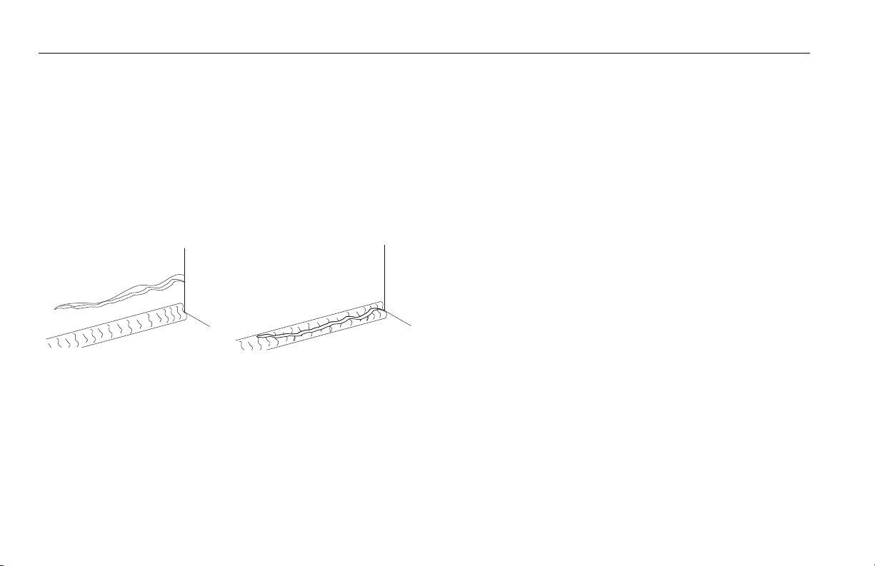
Figure 4-1. Grades and Sideslopes
4-4 – JLG Lift – 3121156
Page 59

SECTION 4 - MACHINE OPERATION
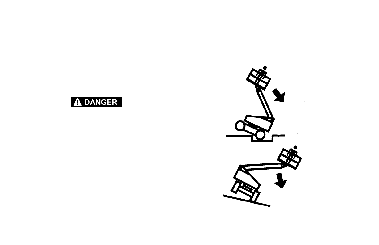
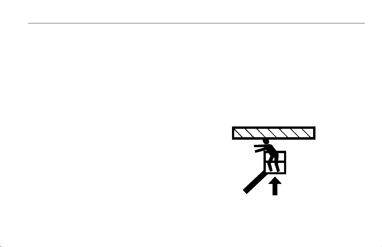
Figure 4-2. Machine Motion Hazard
3121156 – JLG Lift – 4-5
Page 60

SECTION 4 - MACHINE OPERATION
USE EXTREME CAUTION WHEN APPROACHING A CREST OF ANY TERRAIN OBSTACLE. CHECK FOR CURBS, LARGE STONES, OR OTHER TERRAIN OBSTACLES INCLUDING OVERHEAD OBSTACLES AS THE
MACHINE WILL MAKE UNCONTROLLED PIVOTING MOTIONS WHEN THE
CENTER OF GRAVITY (CENTER OF TRACK FRAME) SHIFTS OVER AN
EDGE. SLOW DOWN TO MINIMIZE ACCELERATION DURING PIVOTING
MOVEMENT.
BEFORE DRIVING, MAKE SURE THE BOOM IS POSITIONED OVER THE
REAR OF THE CHASSIS (OVER FINAL DRIVES AND SPROCKETS). IF THE
BOOM IS OVER THE FRONT OF THE CHASSIS (OVER THE IDLER
WHEELS) STEER AND DRIVE CONTROLS WILL MOVE IN OPPOSITE
DIRECTIONS TO MACHINE CONTROLS.
Traveling Forward or Reverse
1. With engine running, depress footswitch and position
DRIVE control to FORWARD and hold for the duration of
forward travel desired.
2. Depress footswitch and position DRIVE control to
REVERSE and hold for duration of reverse travel
desired.
3. Depress footswitch, move joystick (DRIVE/STEER CON-
TROL) to select desired direction of travel (forward or
reverse), move DRIVE/STEER control to RIGHT for
smooth turn to right and LEFT for smooth turn to left.
4. To obtain sharp turns, move DRIVE SPEED/TORQUE
SELECT switch to the back position, slow down the
travel speed and move the DRIVE control lever to RIGHT
for a turn to the right and to LEFT for a turn to the left.
The sharpest possible turn is achieved when the joystick
is in the position to command one track to stop and the
other to move slowly.
TURN IN PLACE ONLY IN AN AREA FREE OF OBSTACLES AND ONLY
WITH THE BOOM FULLY RETRACTED. USE SLOW, GENTLE CONTROL
MOVEMENTS AND DO NOT OPERATE ANY OTHER FUNCTIONS DURING
COUNTER-ROTATION.
5. To obtain counter-rotation (turn in place), stop the
machine, move the DRIVE/STEER control lever directly
to RIGHT to get clockwise rotation and to LEFT to get
counterclockwise rotation.
6. To obtain maximum travel speed, position the DRIVE
controller to FAST and activate the following switches:
a. Position DRIVE SPEED/TORQUE SELECT switch to
FAST. (Forward Position)
4-6 – JLG Lift – 3121156
Page 61

SECTION 4 - MACHINE OPERATION
7. Prior to stopping the machine, position switches as fol-
lows:
a. Position DRIVE SPEED/TORQUE SELECT switch to
LOW. (Backward Position)
8. For traveling up grades, position switches as follows:
a. Position DRIVE SPEED/TORQUE SELECT switch to
HIGH. (Backward position)
NOTE: For smoother operation when driving with fully extended
boom, place DRIVE control to SLOW before stopping.
This machine is equipped with a Drive Orientation Indicator.
The yellow light on the platform control console indicates
that the boom is swung beyond the rear and the machine
may Drive/Steer in the opposite direction from the movement
of the controls. If the indicator is illuminated, operate the
Drive function in the following manner:
1. Match the black and white direction arrows on both plat-
form control panel and the chassis to determine the
direction the machine will travel.
2. Push and release the Drive Orientation Override switch.
Within 3 seconds, slowly move the Drive control toward
the arrow matching the intended direction of machine
travel. The indicator light will flash during the 3 second
interval until the drive function is selected.
3121156 – JLG Lift – 4-7
Page 62

SECTION 4 - MACHINE OPERATION
Figure 4-3. Position of Least Backward Stability
PLATFORM ROTATED
90 DEGREES
MACHINE WILL UPSET
IN THIS DIRECTION IF
OVERLOADED OR
OPERATED ON AN
OUT-OF-LEVEL SURFACE
MAIN BOOM FULLY
RETRACTED AND
ELEVATED
Stability
Machine stability is based on two positions which are called
FORWARD STABILITY and BACKWARD STABILITY. The
machines position of least forward stability is shown in Figure 4-4., and its position of least backward stability is shown
in Figure 4-3.
TO AVOID FORWARD OR BACKWARD UPSET, DO NOT OVERLOAD
MACHINE OR OPERATE ON AN OUT-OF-LEVEL SURFACE.
4-8 – JLG Lift – 3121156
Page 63

Figure 4-4. Position of Least Forward Stability
MACHINE WILL UPSET IN THIS
DIRECTION IF OVERLOADED
OR OPERATED ON AN
OUT-OF-LEVEL SURFACE
LEVEL SURFACE
BOOM FULLY EXTENDED
@ HORIZONTAL (O DEGREES)
SECTION 4 - MACHINE OPERATION
3121156 – JLG Lift – 4-9
Page 64

SECTION 4 - MACHINE OPERATION
4.4 STEERING
Depress footswitch. Move the DRIVE/STEER control lever to
RIGHT for a turn to the right and to LEFT for a turn to the left.
BEFORE OPERATING MACHINE, MAKE SURE BOOM IS POSITIONED
OVER REAR OF CHASSIS. IF BOOM IS OVER FRONT OF THE CHASSIS,
STEER AND DRIVE CONTROLS WILL MOVE IN OPPOSITE DIRECTION
THAN INDICATED ON MACHINE PLACARDS.
4.5 PARKING AND STOWING
Park and stow machine as follows:
1. Park machine in travel position; boom lowered over rear,
all access panels and doors closed and secured, ignition off, turntable locked.
2. Check that brakes hold machine in position.
3. Chock tracks front and rear.
4. Turn off SELECT switch and remove key.
5. When parking on frozen ground overnight, drive the
machine up on boards to prevent freezing to the
ground.
4.6 PLATFORM
Platform Level Adjustment
1. Leveling UP. Depress footswitch. To raise platform, posi-
tion PLATFORM LEVEL control switch UP and hold until
platform is level.
2. Leveling DOWN. Depress footswitch. To lower platform,
position PLATFORM LEVEL control switch to DOWN and
hold until platform is level.
ONLY USE THE PLATFORM LEVELING OVERRIDE FUNCTION FOR
SLIGHT LEVELING OF THE PLATFORM. INCORRECT USE COULD CAUSE
THE LOAD/OCCUPANT TO SHIFT OR FALL. FAILURE TO DO SO COULD
RESULT IN DEATH OR SERIOUS INJURY.
Platform Rotation
1. Depress footswitch to rotate platform to the left, PLAT-
FORM ROTATE control is positioned to the LEFT and
held until desired position is reached.
2. Depress footswitch to rotate platform to the right, PLAT-
FORM ROTATE control is positioned to the RIGHT and
held until desired position is reached.
4-10 – JLG Lift – 3121156
Page 65

SECTION 4 - MACHINE OPERATION
4.7 BOOM
A TILT ALARM WARNING LIGHT, LOCATED ON THE CONTROL CONSOLE,
LIGHTS WHEN THE CHASSIS IS ON A SEVERE SLOPE (5 DEGREES OR
GREATER). DO NOT SWING, EXTEND OR RAISE MAIN BOOM ABOVE
HORIZONTAL WHEN LIT.
DO NOT DEPEND ON TILT ALARM AS A LEVEL INDICATOR FOR THE
CHASSIS. TILT ALARM INDICATES CHASSIS IS ON A SEVERE SLOPE (5
DEGREES OR GREATER). CHASSIS MUST BE LEVEL BEFORE SWINGING, EXTENDING OR RAISING BOOM ABOVE HORIZONTAL.
TO AVOID UPSET, IF TILT ALARM WARNING LIGHT LIGHTS WHEN MAIN
BOOM IS EXTENDED OR RAISED ABOVE HORIZONTAL, RETRACT AND
LOWER PLATFORM TO NEAR GROUND LEVEL. THEN REPOSITION
MACHINE SO THAT CHASSIS IS LEVEL BEFORE EXTENDING OR RAISING MAIN BOOM.
TRAVELING WITH MAIN BOOM RETRACTED AND BELOW HORIZONTAL
IS PERMITTED ON GRADES AND SIDE SLOPES SPECIFIED ON CAUTION
PLACARD AT PLATFORM.
TO AVOID SERIOUS INJURY, DO NOT OPERATE MACHINERY IF ANY
CONTROL LEVERS OR TOGGLE SWITCHES CONTROLLING PLATFORM
MOVEMENT DO NOT RETURN TO THE OFF OR NEUTRAL POSITION
WHEN RELEASED.
TO AVOID A COLLISION AND INJURY IF PLATFORM DOES NOT STOP
WHEN A CONTROL SWITCH OR LEVER IS RELEASED, REMOVE FOOT
FROM FOOTSWITCH OR USE EMERGENCY STOP TO STOP THE
MACHINE.
Swinging the Boom
ASSURE THAT TURNTABLE LOCK IS DISENGAGED BEFORE STARTING
ANY SWING OPERATION.
Depress footswitch. To swing boom, position SWING control
switch or controller to RIGHT or LEFT for direction desired.
NOTE: When boom functions are being operated there an inter-
lock prevents the use of DRIVE and STEER functions.
Raising and Lowering the Main Boom
To raise and lower Main Boom, position MAIN LIFT control
switch or controller to UP OR DOWN and hold until desired
height is reached.
3121156 – JLG Lift – 4-11
Page 66

SECTION 4 - MACHINE OPERATION
Telescoping the Main Boom
To extend or retract Main Boom, position MAIN TELESCOPE
control switch to IN or OUT and hold until platform reaches
desired position.
4.8 SHUT DOWN AND PARK
1. Drive machine to a protected area.
2. Assure main boom is fully retracted and lowered over
rear (Drive) axle; all access panels and doors closed
and secured.
3. Remove all load and allow engine to operate 3-5 min-
utes at LOW setting to permit reduction of engine internal temperatures.
4. At Ground Controls, turn KEY SELECT switch to (center)
OFF. Position POWER/EMERGENCY STOP switch
(down) to OFF. Remove key.
5. Cover Platform Control console to protect instruction
placards, warning decals and operating controls from
hostile environment.
4.9 TIE DOWN AND LIFTING
Tie Down
WHEN TRANSPORTING THE MACHINE, THE BOOM MUST BE FULLY
LOWERED INTO THE BOOM REST.
1. Place the boom in the stowed position with the turntable
locked.
2. Remove all loose items from the machine.
3. Secure the chassis and the platform using straps or
chains of adequate strength and attached to the designated tie down points. (See Figure 4-5., Machine Tie
Down.)
Lifting
(See Figure 4-6., Lifting Chart)
1. Weigh the individual unit, refer to the Serial Number
plate or call JLG Industries to find out the Gross Vehicle
Weight.
2. Place the boom in the stowed position with the turntable
locked.
4-12 – JLG Lift – 3121156
Page 67

SECTION 4 - MACHINE OPERATION
3. Remove all loose items from the machine.
4. Attach lifting device and equipment only to the desig-
nated lifting points.
5. Properly adjust the rigging to prevent damage to the
machine and so the machine remains level.
4.10 AUXILIARY POWER
A toggle type auxiliary power control switch is located on the
platform control station and another is located on the ground
control station. Operation of either switch turns on the electrically driven auxiliary hydraulic pump. This should be used in
case of failure of the main power plant. The auxiliary pump
will operate boom lift, telescope and swing. To activate auxiliary power:
1. Position PLATFORM/GROUND SELECT KEY SWITCH to
PLATFORM.
2. Position POWER/EMERGENCY STOP switch to ON.
3. Depress and hold footswitch.
4. Operate appropriate control switch, lever or controller
for desired function and hold.
5. Position AUXILIARY POWER switch to ON and hold.
6. Release AUXILIARY POWER switch, selected control
switch, lever or controller, and footswitch.
7. Position POWER/EMERGENCY STOP switch to OFF.
To activate auxiliary power from the ground control station:
1. Position PLATFORM/GROUND SELECT KEY SWITCH to
GROUND.
2. Position POWER/EMERGENCY STOP switch to ON.
3. Operate appropriate control switch or controller for
desired function and hold.
4. Position AUXILIARY POWER switch to ON and hold.
5. Release AUXILIARY POWER switch, and appropriate
control switch or controller.
6. Position POWER/EMERGENCY STOP switch to OFF.
3121156 – JLG Lift – 4-13
Page 68

SECTION 4 - MACHINE OPERATION
Figure 4-5. Machine Tie Down
NOTE: When transporting machine over rough terrain or
long distance the boom needs to be chocked and
strapped whenever the base boom is unable to rest on
its pad. This prevents the boom from "Bouncing"
up and down preventing possible damage while transporting.
4-14 – JLG Lift – 3121156
Page 69

SECTION 4 - MACHINE OPERATION
Figure 4-6. Lifting Chart
3121156 – JLG Lift – 4-15
Page 70

SECTION 4 - MACHINE OPERATION
4.11 HYDRAULIC TOOL CIRCUIT INSTRUCTIONS (OPTIONAL)
Tool Circuit
To Operate: (with engine running and foot switch released).
1. Be sure hydraulic switch is in the “OFF” position.
Located on the left side of platform below console box.
2. Make sure the hydraulic tool about to be operated is at a
“safe” setting.
3. Plug tool it into quick-disconnect fittings mounted on
platform rail. The male quick connect is the pressure
feed line.
4. Set flow control knob to desired setting.
4-16 – JLG Lift – 3121156
Page 71

SECTION 4 - MACHINE OPERATION
NOTE: Each notch in the flow control knob corresponds to
approximately 1 GPM (ex. setting 2 = 2 GPM). At setting
seven (7) the pump has reached its maximum flow rate
therefore any setting past 7 will produce no additional
flow.
5. Turn hydraulic power tool switch to the “ON” position.
Oil will now flow to the tool. It is possible to adjust the
flow control knob during operation to achieve desired
tool performance.
6. When finished, turn the hydraulic tool switch to the
“OFF” position.
7. Disconnect tool from the quick-disconnects.
TURN HYDRAULIC TOOL SWITCH TO THE “OFF” POSITION IN ORDER
TO SWITCH TOOLS.
NOTE: The tool circuit will not work with the foot switch
depressed. If the foot switch is depressed during tool circuit operation the tool circuit will stop functioning until the
foot switch is released.
NOTE: The tool is designed to operate at 2600 psi. If necessary
this can be adjusted for a higher or lower pressure.
NOTE: With the foot switch released to operate the tool circuit all
drive and boom functions are cut out.
3121156 – JLG Lift – 4-17
Page 72

SECTION 4 - MACHINE OPERATION
4.12 PLACARDS AND DECALS
Read and understand all placards and decals. Do not operate any machine on which DANGER, WARNING, CAUTION
OR INSTRUCTION PLACARDS OR DECALS ARE MISSING
OR ILLEGIBLE. Replace placards and decals if damaged,
missing or illegible.
Decals are made of Lexan Pressure Sensitive Adhesive with
a protective film on the front. Remove the damaged decal
and thoroughly clean surface before installing a new decal.
Simply peel off, press on to surface.
NOTE: Placards and Decals can be ordered by using part num-
bers located by each placard or decal. (See Figure 4-7.,
Figure 4-13., and Figure 4-15.)
4-18 – JLG Lift – 3121156
Page 73

SECTION 4 - MACHINE OPERATION
39
27
R
33
B
B
41
27
WARNING
CRUSHING HAZARD
1703953 A
Do not stand under a raised platform or boom,
or between a rotating platform and the boom.
Keep all body parts away from any moving components.
Failure to follow these instructions could
result in death or serious in ju ry .
DANGER
ELECTROCUTION HAZARD
1703805 B
This machine is not insulated.
Maintain a clearance of at least 10 ft. between any part of machine
or load and any electrical line or appar tus charged up to 50,000 volts.
One footaddtional clearance is required foreach addtional 30,00
volts or less.
Allowances must be made for error, machine deflection and
electrical line swaying.
Failure to follow these instructions could
result in death or serious injury.
61
55
22
28
Figure 4-7. Decal Installation - Sheet 1 of 10
3121156 – JLG Lift – 4-19
Page 74

SECTION 4 - MACHINE OPERATION
VIEW A-A
27
CE/AUS
1705961
28
CE
1701518
WARNING
CRUSHING HAZARD
1703804 B
Do not stand under a raised platform or boom,
or between a rotating platform and t he boom.
Keep all body parts away from any moving components.
Failure to follow these instructions could
result in death or serious injury.
DANGER
ELECTROCUTION HAZARD
1703805 B
This machine is not insulated.
Maintain a clearance of at least 10 ft. between any part of machine
or load and any electrical line or a ppartus charged up to 50,000 volts.
One footaddtional clearance is requi red foreach ad dtional 30,00
volts or less.
Allowances must be made for error, m achine deflection and
electrical line swaying.
Failure to follow these instructions could
result in death or serious injury.
28
27
CE ONLY
1701518
28
27
24
28
60
40 55
A
A
R
A
N
S
I
22
DANGER
ELECTROCUTION HAZARD
1703805 B
This machine is not insulated.
Maintain a clearance of at least 10 ft. between any part of machine
or load and any electrical line or appartus charged up to 50 ,000 volts.
One footaddtional clearance is required foreach addtional 30,00
volts or less.
Allowances must be made for error, machine deflection and
electrical line swaying.
Failure to follow these instructions could
result in death or serious injury.
WARNING
CRUSHING HAZARD
1703953 A
Do not stand under a raised platform or boom,
or between a rotating platform and the boom.
Keep all body parts away from any moving components.
Failure to follow these ins t r uc ti o n s cou ld
result in death or serious injury.
59
36
26
33
Figure 4-8. Decal Installation - Sheet 2 of 10
4-20 – JLG Lift – 3121156
Page 75

SECTION 4 - MACHINE OPERATION
VIEW
D-D
1
7
0
3
8
1
4
1
7
0
3
8
1
1
11
10
D
D
E
E
GRADALL UNDERCARRIAGE
2
16
16
2
6
32
38 55
15
VIEW
E-E
11
2
Figure 4-9. Decal Installation - Sheet 3 of 10
3121156 – JLG Lift – 4-21
Page 76

SECTION 4 - MACHINE OPERATION
CATERPILLAR UNDERCARRIAGE
600 SC ANSI
VIEW D - D
600SC BOTH SIDES
VIEW E - E
600SC BOTH SIDES
D
D
E
E
TYPICAL ON ALL
CAT MODELS
11
2
10
11
6
Figure 4-10. Decal Installation - Sheet 4 of 10
4-22 – JLG Lift – 3121156
Page 77

SECTION 4 - MACHINE OPERATION
CATERPILLAR UNDERCARRIAGE
600SC CE/AUS
D
D
E
E
*
*
*
* NOTE:
TYPICAL FOR ALL THREE
MODELS OF CAT UNDERCARRIAGE
*
* CAT S/N
NAMETAG
55
38
32
15
VIEW D - D
600SC BOTH SIDES
VIEW E - E
600SC BOTH SIDES
11
2
10
11
Figure 4-11. Decal Installation - Sheet 5 of 10
3121156 – JLG Lift – 4-23
Page 78

SECTION 4 - MACHINE OPERATION
CATERPILLAR UNDERCARRIAGE
660SC
FORWARD
REVERSE
TYP.
TYP.
2
10
11
11
11
11
VIEW D - D
600SC BOTH SIDES
VIEW E - E
600SC BOTH SIDES
11
2
10
11
Figure 4-12. Decal Installation - Sheet 6 of 10
4-24 – JLG Lift – 3121156
Page 79

SECTION 4 - MACHINE OPERATION
TYPICAL BOTH SIDES
62
2
2
16
16
Figure 4-13. Decal Installation - Sheet 7 of 10
3121156 – JLG Lift – 4-25
Page 80

SECTION 4 - MACHINE OPERATION
30
R
41
22
CALLED OUT ON MACHINE
LIFTING ATTACH INSL'L
3251243
120V - 60HZ
17
37
1
7
0
3
8
1
1
28
14
ANSI
CE
1
7
0
3
8
1
1
1
7
0
3
8
1
1
WARNING
CRUSHING HAZARD
1703953 A
Do not stand under a raised platform or boom,
or between a rotating platform and the boom.
Keep all body parts away from any moving components.
Failure to follow these instruct io ns c ou ld
result in death or serious injury.
1701518
CE/AUS
ONLY
62
1700584
ANSI
27
DANGER
ELECTROCUTION HAZARD
1703805 B
This machine is not insulated.
Maintain a clearance of at least 10 ft. between any part of machine
or load and any electrical line or a ppartus charged up to 50,000 volts.
One footaddtional clearance is requi red foreach addtional 30,00
volts or less.
Allowances must be made for error, m achine deflection and
electrical line swaying.
Failure to follow these instruct io ns could
result in death or serious injury.
Figure 4-14. Decal Installation - Sheet 8 of 10
4-26 – JLG Lift – 3121156
Page 81

SECTION 4 - MACHINE OPERATION
58
Figure 4-15. Decal Installation - Sheet 9 of 10
3121156 – JLG Lift – 4-27
Page 82

SECTION 4 - MACHINE OPERATION
Figure 4-16. Decal Installation - Sheet 10 of 10
4-28 – JLG Lift – 3121156
Page 83

SECTION 4 - MACHINE OPERATION
Table 4-1. 600SC Decal Legend - Prior to S/N 0300148842
Item # ANSI
0273906-6
1- - - - - - - -
2 1701499 1701499 1701499 1701499
3 1701502 1701502 1701502 1701502
4 1701503 1701503 1701503 1701503
5 1701509 1701509 1701509 1701509
6 1701529 1701529 1701529 1701529
7- - - - - - - -
8- - - - - - - -
9- - - - - - - -
10 1703811 1703811 1703811 1703811
11 1703814 1703814 1703814 1703814
12 1704277 1704277 1704277 1704277
13 1704412 1704412 1704412 1704412
14 1705084 1705084 1705084 1705084
15 1705514 1705514 1705514 1705514
16 1704461 1704461 1704461 1704461
17 3251243 3251243 3251243 3251243
Canadian
French
0273982-7
CE/
Australian
0273985-5
English/
Portuguese
1001093424-4
Table 4-1. 600SC Decal Legend - Prior to S/N 0300148842
Item # ANSI
0273906-6
18- -- -- - - -
19 - - - - - - 1705904
20 - - - - - - 1705906
21 - - - - - - 1705901
22 170 3953 1703942 - - 1705903
23- -- -- - - -
24 170 2868 1704000 - - 1705967
25 1703797 1703924 1705921 1705895
26 1705336 1705347 1705822 1705896
27 1703804 1703948 1701518 1705898
28 1703805 1703936 1705961 1705897
29 - - 1703984 170582 8 1705902
30 325 1813 3251813 - - 3251813
31- -- -- - - -
32 1702631 1702631 1702631 1702631
33 1704434 1703165 1704434 1704434
34- -- -- - - -
35 1704096 1704099 1705978 1706380
Canadian
French
0273982-7
CE/
Australian
0273985-5
English/
Portuguese
1001093424-4
3121156 – JLG Lift – 4-29
Page 84

SECTION 4 - MACHINE OPERATION
Table 4-1. 600SC Decal Legend - Prior to S/N 0300148842
Item # ANSI
0273906-6
36 1707014 1707046 1705978 1707051
37 1704885 1704885 1704885 1704885
38 1706948 1706948 - - 1706948
39 1705177 1705177 1705177 1705177
40 - - - - - - - -
41 - - - - - - - -
42 - - - - - - - -
43 - - - - - - - -
44 - - - - - - - -
45 - - - - - - - -
46 - - - - - - - -
47 - - - - - - - -
48 - - - - - - - -
49 - - - - - - - -
50 - - - - - - - -
51 - - - - - - - -
52 - - - - - - - -
53 - - - - - - - -
Canadian
French
0273982-7
CE/
Australian
0273985-5
English/
Portuguese
1001093424-4
Table 4-1. 600SC Decal Legend - Prior to S/N 0300148842
Item # ANSI
0273906-6
54- -- -- - - -
55- -- -- - - -
56- -- -- - - -
57 1704468 1001093684 1704468 1001093439
58 1001108494 1001108494 - - 1001108494
59 170 6943 1706943 - - 1706943
60- -- -- - - -
61- -- -- - - -
62 1700584 1700584 1700584 1700584
Canadian
French
0273982-7
CE/
Australian
0273985-5
English/
Portuguese
1001093424-4
4-30 – JLG Lift – 3121156
Page 85

SECTION 4 - MACHINE OPERATION
Table 4-2. 600SC Decal Legend - S/N 0300148842 to Present
Item # ANSI
0273906-9
1- -- -- - - - - - - -
2 1701499 1701499 1701499 1701499 1701499 1701499
3 1701502 1701502 1701502 1701502 1701502 1701502
4 1701503 1701503 1701503 1701503 1701503 1701503
5 1701509 1701509 1701509 1701509 1701509 1701509
6 1701529 1701529 1701529 1701529 1701529 1701529
7- -- -- - - - - - - -
8- -- -- - - - - - - -
9- -- -- - - - - - - -
10 1703811 1703811 1703811 1703811 1703811 1703811
11 1703814 1703814 1703814 1703814 1703814 1703814
12 1704277 1704277 1704277 1704277 1704277 1704277
13 1704412 1704412 1704412 1704412 1704412 1704412
14 1705084 1705084 1705084 1705084 1705084 1705084
15 1705514 1705514 1705514 1705514 1705514 1705514
16 1704461 1704461 1704461 1704461 1704461 1704461
17 3251243 3251243 3251243 3251243 3251243 3251243
18- -- -- - - - - - - -
Canadian
French
0273982-9
CE/
Australian
0273985-6
English/
Portuguese
1001093424-7
Simplified
Chinese
1001116970-3
Traditional
Chinese
1001116971-3
3121156 – JLG Lift – 4-31
Page 86

SECTION 4 - MACHINE OPERATION
Table 4-2. 600SC Decal Legend - S/N 0300148842 to Present
Item # ANSI
0273906-9
19 - - - - - - 1705904 1705342 1001117034
20 - - - - - - 1705906 1705507 1001117035
21- -- -- - - - - - - -
22 1703 953 1703942 - - 1705903 1001116845 1703943
23- -- -- - - - - - - -
24 1702868 1704000 - - 1705967 1705968 1001116846
25 1703797 1703924 1705921 1705895 1001116847 1703925
26 1705336 1705347 1705822 1705896 1001116848 1001116849
27 1703804 1703948 1701518 1705898 1001116850 1703949
28 1703805 1703936 1705961 1705897 1703937 1001116851
29 - - 1703984 1705828 1705902 1001116852 1703982
30- -- -- - - - - - - -
31- -- -- - - - - - - -
32 - - 1702631 - - - - - - - -
33 1704434 1703165 1704434 1704434 1704434 1704434
34- -- -- - - - - - - -
35 1001121800 1001121802 1705978 1001121806 1001121811 1001121809
36 1001121813 1001121815 1705978 1001121819 1001121824 1001121822
Canadian
French
0273982-9
CE/
Australian
0273985-6
English/
Portuguese
1001093424-7
Simplified
Chinese
1001116970-3
Traditional
Chinese
1001116971-3
4-32 – JLG Lift – 3121156
Page 87

SECTION 4 - MACHINE OPERATION
Table 4-2. 600SC Decal Legend - S/N 0300148842 to Present
Item # ANSI
0273906-9
37 1704885 1704885 1704885 1704885 1704885 1704885
38 1706948 1706948 - - 1706948 1706948 1706948
39 1705177 1705177 1705177 1705177 1705177 1705177
40- -- -- - - - - - - -
41- -- -- - - - - - - -
42- -- -- - - - - - - -
43- -- -- - - - - - - -
44- -- -- - - - - - - -
45- -- -- - - - - - - -
46- -- -- - - - - - - -
47- -- -- - - - - - - -
48- -- -- - - - - - - -
49- -- -- - - - - - - -
50- -- -- - - - - - - -
51- -- -- - - - - - - -
52- -- -- - - - - - - -
53- -- -- - - - - - - -
54- -- -- - - - - - - -
Canadian
French
0273982-9
CE/
Australian
0273985-6
English/
Portuguese
1001093424-7
Simplified
Chinese
1001116970-3
Traditional
Chinese
1001116971-3
3121156 – JLG Lift – 4-33
Page 88

SECTION 4 - MACHINE OPERATION
Table 4-2. 600SC Decal Legend - S/N 0300148842 to Present
Item # ANSI
0273906-9
55- -- -- - - - - - - -
56- -- -- - - - - - - -
57 1704468 1001093684 1704468 1001093439 1001116963 1001116964
58 1001108494 1001108494 - - 1001108494 1001108494 1001108494
59 1706943 1706943 - - 1706943 1706943 1706943
60- -- -- - - - - - - -
61- -- -- - - - - - - -
62 1001131269 1001131269 - - - - - - - -
Canadian
French
0273982-9
CE/
Australian
0273985-6
English/
Portuguese
1001093424-7
Simplified
Chinese
1001116970-3
Traditional
Chinese
1001116971-3
4-34 – JLG Lift – 3121156
Page 89

SECTION 4 - MACHINE OPERATION
Table 4-3. 660SJC Decal Legend - Prior to S/N 0300148842
Item # ANSI
0273908-7
1- - - - - - - -
2 1701499 1701499 1701499 1701499
3 1701502 1701502 1701502 1701502
4 1701503 1701503 1701503 1701503
5 1701509 1701509 1701509 1701509
6 1701529 1701529 1701529 1701529
7- - - - - - - -
8- - - - - - - -
9- - - - - - - -
10 1703811 1703811 1703811 1703811
11 1703814 1703814 1703814 1703814
12 1704277 1704277 1704277 1704277
13 1704412 1704412 1704412 1704412
14 1705084 1705084 1705084 1705084
15 1705514 1705514 1705514 1705514
16 1704461 1704461 1704461 1704461
17 3251243 3251243 3251243 3251243
Canadian
French
0273984-7
CE/
Australian
0273987-6
English/
Portuguese
1001103292-3
Table 4-3. 660SJC Decal Legend - Prior to S/N 0300148842
Item # ANSI
0273908-7
18- -- -- - - -
19 - - - - - - 1705904
20 - - - - - - 1705906
21 - - - - - - 1705901
22 170 3953 1703942 - - 1705903
23- -- -- - - -
24 170 2868 1704000 - - 1705967
25 1703797 1703924 1705921 1705895
26 1705336 1705347 1705822 1705896
27 1703804 1703948 1701518 1705898
28 1703805 1703936 1705961 1705897
29 - - 1703984 170582 8 1705902
30 325 1813 3251813 - - 3251813
31- -- -- - - -
32 1702631 1702631 1702631 1702631
33 1703165 1703165 1703165 1703165
34- -- -- - - -
35 1701645 1707055 1705978 1701645
Canadian
French
0273984-7
CE/
Australian
0273987-6
English/
Portuguese
1001103292-3
3121156 – JLG Lift – 4-35
Page 90

SECTION 4 - MACHINE OPERATION
Table 4-3. 660SJC Decal Legend - Prior to S/N 0300148842
Item # ANSI
0273908-7
36 1707013 1707047 1705978 1707052
37 1704885 1704885 1704885 1704885
38 1706948 1706948 - - 1706948
39 1705177 1705177 1705177 1705177
40 - - 1001093553 - - - -
41 - - - - - - - -
42 - - - - - - - -
43 - - - - - - - -
44 - - - - - - - -
45 - - - - - - - -
46 - - - - - - - -
47 - - - - - - - -
48 - - - - - - - -
49 - - - - - - - -
50 - - - - - - - -
51 - - - - - - - -
52 - - - - - - - -
53 - - - - - - - -
Canadian
French
0273984-7
CE/
Australian
0273987-6
English/
Portuguese
1001103292-3
Table 4-3. 660SJC Decal Legend - Prior to S/N 0300148842
Item # ANSI
0273908-7
54- -- -- - - -
55- -- -- - - -
56- -- -- - - -
57 1704468 1001093684 1704468 1001093439
58 1001108494 1001108494 - - 1001108494
59 170 6943 1706943 - - 1706943
60- -- -- - - -
61- -- -- - - -
62 1700584 1700584 1700584 1700584
Canadian
French
0273984-7
CE/
Australian
0273987-6
English/
Portuguese
1001103292-3
4-36 – JLG Lift – 3121156
Page 91

SECTION 4 - MACHINE OPERATION
Table 4-4. 660SJC Decal Legend - S/N 0300148842 to Present
Item # ANSI
0273908-10
1- - - - - - - -
2 1701499 1701499 1701499 1701499
3 1701502 1701502 1701502 1701502
4 1701503 1701503 1701503 1701503
5 1701509 1701509 1701509 1701509
6 1701529 1701529 1701529 1701529
7- - - - - - - -
8- - - - - - - -
9- - - - - - - -
10 1703811 1703811 1703811 1703811
11 1703814 1703814 1703814 1703814
12 1704277 1704277 1704277 1704277
13 1704412 1704412 1704412 1704412
14 1705084 1705084 1705084 1705084
15 1705514 1705514 1705514 1705514
16 1704461 1704461 1704461 1704461
17 3251243 3251243 3251243 3251243
Canadian
French
0273984-9
CE/
Australian
0273987-7
English/
Portuguese
1001103292-6
Table 4-4. 660SJC Decal Legend - S/N 0300148842 to Present
Item # ANSI
0273908-10
18- -- -- - - -
19 - - - - - - 1705904
20 - - - - - - 1705906
21- -- -- - - -
22 170 3953 1703942 - - 1705903
23- -- -- - - -
24 170 2868 1704000 - - 1705967
25 1703797 1703924 1705921 1705895
26 1705336 1705347 1705822 1705896
27 1703804 1703948 1701518 1705898
28 1703805 1703936 1705961 1705897
29 3532347 1703984 1705828 1705902
30 - - - - - - 3251813
31- -- -- - - -
32 - - 1702631 - - - -
33 1703165 1703165 1703165 1703165
34- -- -- - - -
35 1001121801 1001121803 1705978 1001121801
Canadian
French
0273984-9
CE/
Australian
0273987-7
English/
Portuguese
1001103292-6
3121156 – JLG Lift – 4-37
Page 92

SECTION 4 - MACHINE OPERATION
Table 4-4. 660SJC Decal Legend - S/N 0300148842 to Present
Item # ANSI
0273908-10
36 1001121814 1001121816 1705978 1001121655
37 1704885 1704885 1704885 1704885
38 1706948 1706948 - - 1706948
39 1705177 1705177 1705177 1705177
40 - - 1001093553 - - 1001093553
41 - - - - - - - -
42 - - - - - - - -
43 - - - - - - - -
44 - - - - - - - -
45 - - - - - - - -
46 - - - - - - - -
47 - - - - - - - -
48 - - - - - - - -
49 - - - - - - - -
50 - - - - - - - -
51 - - - - - - - -
52 - - - - - - - -
53 - - - - - - - -
Canadian
French
0273984-9
CE/
Australian
0273987-7
English/
Portuguese
1001103292-6
Table 4-4. 660SJC Decal Legend - S/N 0300148842 to Present
Item # ANSI
0273908-10
54- -- -- - - -
55- -- -- - - -
56- -- -- - - -
57 1704468 1001093684 1704468 1001093439
58 1001108494 1001108494 - - 1001108494
59 170 6943 1706943 - - 1706943
60- -- -- - - -
61- -- -- - - -
62 1001131269 100113126 9 - - - -
Canadian
French
0273984-9
CE/
Australian
0273987-7
English/
Portuguese
1001103292-6
4-38 – JLG Lift – 3121156
Page 93

SECTION 5. EMERGENCY PROCEDURES
5.1 GENERAL
This section explains the steps to be taken in case of an
emergency situation while operating.
5.2 INCIDENT NOTIFICATION
JLG Industries, Inc. must be notified immediately of any incident involving a JLG product. Even if no injury or property
damage is evident, the factory should be contacted by telephone and provided with all necessary details.
In USA:
JLG Phone: 877-JLG-SAFE (554-7233)
(8am till 4:45pm EST)
Outside USA:
240-420-2661
E-mail:
ProductSafety@JLG.com
Failure to notify the manufacturer of an incident involving a
JLG Industries product within 48 hours of such an occurrence may void any warranty consideration on that particular
machine.
SECTION 5 - EMERGENCY PROCEDURES
FOLLOWING ANY ACCIDENT, THOROUGHLY INSPECT THE MACHINE
AND TEST ALL FUNCTIONS FIRST FROM THE GROUND CONTROLS,
THEN FROM THE PLATFORM CONTROLS. DO NOT LIFT ABOVE 3 M (10
FT.) UNTIL YOU ARE SURE THAT ALL DAMAGE HAS BEEN REPAIRED, IF
REQUIRED, AND THAT ALL CONTROLS ARE OPERATING CORRECTLY.
3121156 – JLG Lift – 5-1
Page 94

SECTION 5 - EMERGENCY PROCEDURES
5.3 EMERGENCY OPERATION
Operator Unable to Control Machine
IF THE PLATFORM OPERATOR IS PINNED, TRAPPED OR
UNABLE TO OPERATE OR CONTROL MACHINE:
1. Other personnel should operate the machine from
ground controls only as required.
2. Other qualified personnel on the platform may use the
platform controls. DO NOT CONTINUE OPERATION IF
CONTROLS DO NOT FUNCTION PROPERLY.
3. Cranes, forklift trucks or other equipment can be used to
remove platform occupants and stabilize motion of the
machine.
Platform or Boom Caught Overhead
If the platform or boom becomes jammed or snagged in
overhead structures or equipment, rescue platform occupants prior to freeing the machine.
5-2 – JLG Lift – 3121156
Page 95

SECTION 6 - GENERAL SPECIFICATIONS & OPERATOR MAINTENANCE
SECTION 6. GENERAL SPECIFICATIONS & OPERATOR MAINTENANCE
6.1 INTRODUCTION
This section of the manual provides additional necessary
information to the operator for proper operation and maintenance of this machine.
The maintenance portion of this section is intended as information to assist the machine operator to perform daily maintenance tasks only, and does not replace the more thorough
Preventive Maintenance and Inspection Schedule included
in the Service and Maintenance Manual.
Other Publications Available:
Service and Maintenance Manual ............................ 3121157
Illustrated Parts Manual (Prior to S/N - 128000
Gradall Chassis)..................................................... 3121158
Illustrated Parts Manual (S/N - 128000 to Present) .. 3121251
6.2 OPERATING SPECIFICATIONS
Table 6-1. Operating Specifications - Prior to S/N 0300148842
Maximum Work Load (Capacity)
U n re s tr i ct e d:
R es t r ic t ed - 60 0 SC
R es t r ic t ed - 66 0 SJ C
Maximum Travel Grade (Gradeability)*
Maximum Travel Grade (Side Slope)*
Max.Vertical Platform Height:
600SC
660SJC
Max.Horizontal Platform Reach:
600SC
660SJC
Tu rn in g R ad iu s 0
Maximum Ground Bearing Pressure
600SC
660SJC
Maximum Drive Speed: 1.6 mph (2.6 kph)
500 lb. (230 kg)
1000 lb. (450 kg)
500 lb. (230 kg)
55%
60 ft. 3 in. (18.36 m)
66 ft. 8 in. (20.32 m)
49 ft. 6 in. (15.09 m)
56 ft. 9 in. ( 17.3 m)
5.45 psi (0.383 kg/cm2)
6.5 psi (0.457 kg/cm
5°
2
)
3121156 – JLG Lift – 6-1
Page 96

SECTION 6 - GENERAL SPECIFICATIONS & OPERATOR MAINTENANCE
Table 6-1. Operating Specifications - Prior to S/N 0300148842
Max. Hydraulic System Pressure 4500 psi (310 Bar)
Maximum Wind Speed 28 mph (12.5 m/s)
Maximum Manual Force 101 lb. (450 N)
Electrical System Voltage 12 Volts
Gross Machine Weight
6 0 0S C
6 6 0S J C
(Platform Empty)
22,500 lb. (10,205 kg)
27,100 lb. (12,292 kg)
* W it h bo o m in s to w ed p o si t io n .
Table 6-2. Operating Specifications - S/N 0300148842 to
Present
Maximum Work Load (Capacity) - ANSI
U n re s tr i ct e d:
R es t r ic t ed - 60 0 SC
R es t r ic t ed - 66 0 SJ C
Maximum Work Load (Capacity) - CE &
Australia
U n re s tr i ct e d:
R es t r ic t ed - 60 0 SC
R es t r ic t ed - 66 0 SJ C
Maximum Travel Grade (Gradeability)
*
500 lb. (227 kg)
1000 lb. (454 kg)
500 lb. (227 kg)
500 lb. (230 kg)
1000 lb. (450 kg)
500 lb. (230 kg)
55%
Table 6-2. Operating Specifications - S/N 0300148842 to
Present
Maximum Travel Grade (Side Slope)*
Max.Vertical Platform Height:
600SC
660SJC
Max.Horizontal Platform Reach:
600SC
660SJC
Tu rn in g R ad iu s 0
Maximum Ground Bearing Pressure
600SC
660SJC
Maximum Drive Speed: 1.6 mph (2.6 kph)
Max. Hydraulic System Pressure 4500 psi (310 Bar)
Maximum Wind Speed 28 mph (12.5 m/s)
Maximum Manual Force 101 lb. (450 N)
Electrical System Voltage 12 Volts
Gross Machine Weight
6 0 0S C
6 6 0S J C
(Platform Empty)
60 ft. 3 in. (18.36 m)
66 ft. 8 in. (20.32 m)
49 ft. 6 in. (15.09 m)
56 ft. 9 in. ( 17.3 m)
5.45 psi (0.383 kg/cm2)
6.5 psi (0.457 kg/cm
22,500 lb. (10,205 kg)
27,100 lb. (12,292 kg)
* With boom in stowed position.
5°
2
)
6-2 – JLG Lift – 3121156
Page 97

SECTION 6 - GENERAL SPECIFICATIONS & OPERATOR MAINTENANCE
Capacities Engine Data
Table 6-3. Capacities
Fuel Tank 39 US. Gallons (147.6 L)
Hydraulic Oil Tank 31 U.S. Gallons (117.3 L)
Hydraulic System (Includi ng Tank) 37.2 U.S. Gallons (140.8 L)
Engine Crankcase
D eu t z w/ F il t er
Caterpillar (w/filter)
11 quarts (10.5 L)
10.6 quarts (10 L)
Table 6-4. Deutz F4M1011F/F4M2011 Specifications
Fuel Diesel
Oil Capacity
C oo l i ng S ys t em
Crankcase
To t al C ap a ci t y
Idle RPM 1000
Low RPM 1800
High RPM 2800
Alternator 60 Amp, belt drive
Battery 1000 Cold Cranking Amps, 210
Fuel Consumption
L ow R P M
H ig h R PM
Horsepower 65 @ 3000 RPM, full load
5 Quar ts (4.5 L)
11 Quar ts (10.5 L) w/Filter
16 Quarts (15 L)
Minutes Reserve Capacity, 12
VDC
1.90 GPH (7.19 lph)
2.50 GPH (9.46 lph)
3121156 – JLG Lift – 6-3
Page 98

SECTION 6 - GENERAL SPECIFICATIONS & OPERATOR MAINTENANCE
Table 6-5. Caterpillar 3044C/3.4
Type Four Stroke Cycle
Cylinders 4 in-line
Bore 3.70 inch (94 mm)
Stroke 4.72 inch (120 mm)
Aspiration turbocharged
Compression ratio 19:1
Displacement
Firing Order 1-3-4-2
Rotation (viewed from flywheel) Counterclockwise
Oil Capacity (w/filter) 10.6 quarts (10 L)
Cooling System (Engine Only) 5.8 quarts (5.5 L)
Idle RPM - 3044C 1000
Idle RPM - 3.4 1200
Low RPM 1800
High RPM 2600
Alternator 60 Amp, belt drive
203 in3 (3.33 L)
Hydraulic Oil
Table 6-6. Hydraulic Oil
HYDRAULIC SYSTEM OPERATING
TEMPERATURE RANGE
+0° to +180° F (-18° C to +83° C) 10W
+0° F to +210° F (-18° C to +99° C) 10W-20, 10W-30
+50° F to +210° F (+10° C to +210° C) 20W-20
NOTE: Hydraulic oils must have anti-wear qualities at least to API
Service Classification GL-3, and sufficient chemical stability for mobile hydraulic system service. JLG Industries
recommends Mobilfluid 424 hydraulic oil, which has an
SAE viscosity index of 152.
NOTE: When temperatures remain below 20° F (-7 degrees C),
JLG Industries recommends the use of Mobil DTE 13M.
Aside from JLG recommendations, it is not advisable to mix
oils of different brands or types, as they may not contain the
same required additives or be of comparable viscosities. If
use of hydraulic oil other than Mobilfluid 424 is desired, contact JLG Industries for proper recommendations.
SAE VISCOSITY GRADE
6-4 – JLG Lift – 3121156
Page 99

SECTION 6 - GENERAL SPECIFICATIONS & OPERATOR MAINTENANCE
Table 6-7. Mobilfluid 424 Specs
SAE Grade 10W30
Gravity, API 29.0
Density, Lb/Gal. 60°F 7.35
Pour Point, Max -46°F (-43°C)
Flash Point, Min. 442°F (228°C)
Viscosity
Brookfield, cP at -18°C 2700
at 40° C 55 cSt
at 100° C 9.3 cSt
Viscosity Index 152
Table 6-8. Mobil DTE 13M Specs
ISO Viscosity Grade #32
Specific Gravity 0.877
Pour Point, Max -40?F (-40?C)
Flash Point, Min. 330?F (166?C)
Viscosity
at 40° C 33cSt
at 100° C 6.6 cSt
at 100° F 169 SUS
at 210° F 48 SUS
cp at -20° F 6,200
Viscosity Index 140
3121156 – JLG Lift – 6-5
Page 100

SECTION 6 - GENERAL SPECIFICATIONS & OPERATOR MAINTENANCE
Table 6-9. Exxon Univis HVI 26 Specs
Specific Gravity 32.1
Pour Point -76°F (-60°C)
Flash Point 217°F (103°C)
Viscosity
at 40° C 25.8 cSt
at 100° C 9.3 cSt
Viscosity Index 376
NOTE: Mobil/Exxon recommends that this oil be checked
on a yearly basis for viscosity.
Table 6-10. Quintolubric 888-46
Density
0.91 @ 15°C (59°F)
Pour Poin t
<-20°C (<-4°F)
Flash Point
275°C (527°F)
Fire Point
325°C (617°F)
Autoignition Te mpe ra tu re
450°C (842°F)
Viscosity
at 0° C (32°F) 360 cSt
at 20° C (68°F) 102 cSt
at 40° C (104°F) 46 cSt
at 100° C (212°F) 10 cSt
Viscosity Index 220
6-6 – JLG Lift – 3121156
 Loading...