

Page 1
Service Manual
Models
534D-9,
534D-10
& 544D
534D-9 & 534D-10
S/N 0160000447 & After
544D
S/N 0160000192 & After
31200170
Revised
November 6, 2008
An Oshkosh Corporation Company
Page 2

Page 3

EFFECTIVITY PAGE
February 5, 2007 - A - Original Issue Of Manual
May 7, 2008 - B - Added second battery on page 2.6. Updated Tire Specs on page 2.8. Revised Warnings on pages 3.4,
3.21, 3.32, 4.3, 5.3, 5.11, 5.13, 5.14, 6.3, 8.3 & 8.21. Added Hyd Sub Assy Removal/Install on pages 3.30, 3.31 & 3.32.
Changed Danger, Warning, Caution & Notice as required. Added Fork Info on page 3.43. Added Radiator Cap text on
Page 1.4.
November 6, 2008 - C - Replaced Gradall branding with JLG brand.
31200170 534D-9, 534D-10 & 544D a
Page 4

EFFECTIVITY PAGE
534D-9, 534D-10 & 544D 31200170-b
Page 5

SECTION CONTENTS
Section Subject Page
Section 1
Safety Practices . . . . . . . . . . . . . . . . . . . . . . . . . . . . . . . . . . . . . . . . . . . . . . . . . . . . . . . 1.1
1.1 Introduction . . . . . . . . . . . . . . . . . . . . . . . . . . . . . . . . . . . . . . . . . . . . . . . . . . . . . . . . . . 1.2
1.2 Disclaimer . . . . . . . . . . . . . . . . . . . . . . . . . . . . . . . . . . . . . . . . . . . . . . . . . . . . . . . . . . . 1.2
1.3 Operator & Safety Manual . . . . . . . . . . . . . . . . . . . . . . . . . . . . . . . . . . . . . . . . . . . . . . . 1.2
1.4 Do Not Operate Tags . . . . . . . . . . . . . . . . . . . . . . . . . . . . . . . . . . . . . . . . . . . . . . . . . . . 1.2
1.5 Safety Information . . . . . . . . . . . . . . . . . . . . . . . . . . . . . . . . . . . . . . . . . . . . . . . . . . . . . 1.3
1.6 Safety Instructions . . . . . . . . . . . . . . . . . . . . . . . . . . . . . . . . . . . . . . . . . . . . . . . . . . . . .1.3
1.7 Safety Decals . . . . . . . . . . . . . . . . . . . . . . . . . . . . . . . . . . . . . . . . . . . . . . . . . . . . . . . . . 1.4
Section 2
General Information and Specifications . . . . . . . . . . . . . . . . . . . . . . . . . . . . . . . . . . . . 2.1
2.1 Replacement Parts and Warranty Information . . . . . . . . . . . . . . . . . . . . . . . . . . . . . . . . 2.2
2.2 Torque Charts . . . . . . . . . . . . . . . . . . . . . . . . . . . . . . . . . . . . . . . . . . . . . . . . . . . . . . . .2.3
2.3 Specifications . . . . . . . . . . . . . . . . . . . . . . . . . . . . . . . . . . . . . . . . . . . . . . . . . . . . . . . . . 2.6
2.4 Fluid and Lubricant Capacities. . . . . . . . . . . . . . . . . . . . . . . . . . . . . . . . . . . . . . . . . . . . 2.9
2.5 Service and Maintenance Schedules. . . . . . . . . . . . . . . . . . . . . . . . . . . . . . . . . . . . . . . 2.10
2.6 Lubrication Schedules . . . . . . . . . . . . . . . . . . . . . . . . . . . . . . . . . . . . . . . . . . . . . . . . . . 2.12
Section 3
Boom . . . . . . . . . . . . . . . . . . . . . . . . . . . . . . . . . . . . . . . . . . . . . . . . . . . . . . . . . . . 3.1
3.1 Boom System Component Terminology 534D-9, 534D-10 . . . . . . . . . . . . . . . . . . . . . . 3.3
3.2 Boom System - Three Section . . . . . . . . . . . . . . . . . . . . . . . . . . . . . . . . . . . . . . . . . . . . 3.4
3.3 Boom Maintenance - Three Section (Complete Removal). . . . . . . . . . . . . . . . . . . . . . . 3.4
3.4 Boom Maintenance - Three Section (Individual Section Removal) . . . . . . . . . . . . . . . . 3.9
3.5 Boom Cables - Three Section . . . . . . . . . . . . . . . . . . . . . . . . . . . . . . . . . . . . . . . . . . . . 3.12
3.6 Auxiliary Electric Cable - Three Section. . . . . . . . . . . . . . . . . . . . . . . . . . . . . . . . . . . . . 3.17
3.7 Extend/Retract Cylinder Removal and Installation - Three Section . . . . . . . . . . . . . . . . 3.18
3.8 Boom System Component Terminology 544D . . . . . . . . . . . . . . . . . . . . . . . . . . . . . . . . 3.20
3.9 Boom System - Four Section . . . . . . . . . . . . . . . . . . . . . . . . . . . . . . . . . . . . . . . . . . . . 3.21
3.10 Boom Maintenance - Four Section (Complete Removal). . . . . . . . . . . . . . . . . . . . . . . . 3.21
3.11 Boom Maintenance - Four Section (Individual Section Removal) . . . . . . . . . . . . . . . . . 3.28
3.12 Boom Extend and Retract Chains - Four Section . . . . . . . . . . . . . . . . . . . . . . . . . . . . . 3.32
3.13 Boom Section Separation Adjustment - Four Section . . . . . . . . . . . . . . . . . . . . . . . . . . 3.38
3.14 Hydraulic Sub-Assembly Removal/Installation - Four Section . . . . . . . . . . . . . . . . . . . . 3.38
3.15 Boom Wear Pads . . . . . . . . . . . . . . . . . . . . . . . . . . . . . . . . . . . . . . . . . . . . . . . . . . . . . . 3.41
3.16 Quick Switch Assembly . . . . . . . . . . . . . . . . . . . . . . . . . . . . . . . . . . . . . . . . . . . . . . . . . 3.42
3.17 Forks . . . . . . . . . . . . . . . . . . . . . . . . . . . . . . . . . . . . . . . . . . . . . . . . . . . . . . . . . . . . . . . 3.43
3.18 Troubleshooting . . . . . . . . . . . . . . . . . . . . . . . . . . . . . . . . . . . . . . . . . . . . . . . . . . . . . . . 3.44
Section 4
Cab and Covers . . . . . . . . . . . . . . . . . . . . . . . . . . . . . . . . . . . . . . . . . . . . . . . . . . . . . . . . 4.1
4.1 Operator’s Cab and Covers Component Terminology . . . . . . . . . . . . . . . . . . . . . . . . . . 4.2
4.2 Operator’s Cab. . . . . . . . . . . . . . . . . . . . . . . . . . . . . . . . . . . . . . . . . . . . . . . . . . . . . . . .4.3
4.3 Cab Components . . . . . . . . . . . . . . . . . . . . . . . . . . . . . . . . . . . . . . . . . . . . . . . . . . . . . . 4.3
4.4 Cab Removal . . . . . . . . . . . . . . . . . . . . . . . . . . . . . . . . . . . . . . . . . . . . . . . . . . . . . . . . . 4.8
4.5 Cab Installation . . . . . . . . . . . . . . . . . . . . . . . . . . . . . . . . . . . . . . . . . . . . . . . . . . . . . . . 4.9
534D-9, 534D-10 & 544D
i
Page 6

Section Subject Page
Section 5
Axles, Wheels and Tires . . . . . . . . . . . . . . . . . . . . . . . . . . . . . . . . . . . . . . . . . . . . . . . . . 5.1
5.1 Axles, Wheel and Tire Component Terminology . . . . . . . . . . . . . . . . . . . . . . . . . . . . . . 5.2
5.2 General Information . . . . . . . . . . . . . . . . . . . . . . . . . . . . . . . . . . . . . . . . . . . . . . . . . . . . 5.3
5.3 Axle Assemblies. . . . . . . . . . . . . . . . . . . . . . . . . . . . . . . . . . . . . . . . . . . . . . . . . . . . . . . 5.3
5.4 Rear Drive Hubs. . . . . . . . . . . . . . . . . . . . . . . . . . . . . . . . . . . . . . . . . . . . . . . . . . . . . . . 5.9
5.5 Rear Steer Axle . . . . . . . . . . . . . . . . . . . . . . . . . . . . . . . . . . . . . . . . . . . . . . . . . . . . . . .5.10
5.6 Wheels and Tires . . . . . . . . . . . . . . . . . . . . . . . . . . . . . . . . . . . . . . . . . . . . . . . . . . . . . . 5.11
5.7 Brakes . . . . . . . . . . . . . . . . . . . . . . . . . . . . . . . . . . . . . . . . . . . . . . . . . . . . . . . . . . . . . . 5.13
5.8 Towing a Disabled Machine . . . . . . . . . . . . . . . . . . . . . . . . . . . . . . . . . . . . . . . . . . . . . . 5.13
Section 6
Hydrostatic Drive Pump . . . . . . . . . . . . . . . . . . . . . . . . . . . . . . . . . . . . . . . . . . . . . . . . . 6.1
6.1 Drive Pump Assembly Component Terminology . . . . . . . . . . . . . . . . . . . . . . . . . . . . . . 6.2
6.2 Drive Pump Description . . . . . . . . . . . . . . . . . . . . . . . . . . . . . . . . . . . . . . . . . . . . . . . . . 6.3
6.3 Drive Pump Serial Number . . . . . . . . . . . . . . . . . . . . . . . . . . . . . . . . . . . . . . . . . . . . . . 6.3
6.4 Drive Pump Specifications . . . . . . . . . . . . . . . . . . . . . . . . . . . . . . . . . . . . . . . . . . . . . . . 6.3
6.5 Drive Pump Replacement . . . . . . . . . . . . . . . . . . . . . . . . . . . . . . . . . . . . . . . . . . . . . . . 6.3
6.6 Hydrostatic Drive Performance Checks . . . . . . . . . . . . . . . . . . . . . . . . . . . . . . . . . . . . . 6.5
Section 7
Engine . . . . . . . . . . . . . . . . . . . . . . . . . . . . . . . . . . . . . . . . . . . . . . . . . . . . . . . . . . . 7.1
7.1 Introduction: John Deere 4045TF275 & 4045HF275 . . . . . . . . . . . . . . . . . . . . . . . . . . . 7.2
7.2 Engine Serial Number . . . . . . . . . . . . . . . . . . . . . . . . . . . . . . . . . . . . . . . . . . . . . . . . . . 7.4
7.3 Specifications and Maintenance Information . . . . . . . . . . . . . . . . . . . . . . . . . . . . . . . . . 7.4
7.4 Introduction: Cummins QSB4.5 . . . . . . . . . . . . . . . . . . . . . . . . . . . . . . . . . . . . . . . . . . . 7.5
7.5 Engine Serial Number . . . . . . . . . . . . . . . . . . . . . . . . . . . . . . . . . . . . . . . . . . . . . . . . . . 7.7
7.6 Specifications and Maintenance Information . . . . . . . . . . . . . . . . . . . . . . . . . . . . . . . . . 7.7
7.7 Cooling System . . . . . . . . . . . . . . . . . . . . . . . . . . . . . . . . . . . . . . . . . . . . . . . . . . . . . . . 7.7
7.8 Electrical System . . . . . . . . . . . . . . . . . . . . . . . . . . . . . . . . . . . . . . . . . . . . . . . . . . . . . .7.9
7.9 Fuel System . . . . . . . . . . . . . . . . . . . . . . . . . . . . . . . . . . . . . . . . . . . . . . . . . . . . . . . . . .7.9
7.10 Exhaust System . . . . . . . . . . . . . . . . . . . . . . . . . . . . . . . . . . . . . . . . . . . . . . . . . . . . . . . 7.11
7.11 Air Cleaner Assembly. . . . . . . . . . . . . . . . . . . . . . . . . . . . . . . . . . . . . . . . . . . . . . . . . . . 7.11
7.12 Engine Replacement . . . . . . . . . . . . . . . . . . . . . . . . . . . . . . . . . . . . . . . . . . . . . . . . . . . 7.12
7.13 Engine Drive Plate/Coupling . . . . . . . . . . . . . . . . . . . . . . . . . . . . . . . . . . . . . . . . . . . . . 7.14
7.14 Engine Troubleshooting . . . . . . . . . . . . . . . . . . . . . . . . . . . . . . . . . . . . . . . . . . . . . . . . . 7.15
Section 8
Hydraulic System . . . . . . . . . . . . . . . . . . . . . . . . . . . . . . . . . . . . . . . . . . . . . . . . . . . . . . . 8.1
8.1 Hydraulic Component Terminology . . . . . . . . . . . . . . . . . . . . . . . . . . . . . . . . . . . . . . . . 8.2
8.2 Safety Information . . . . . . . . . . . . . . . . . . . . . . . . . . . . . . . . . . . . . . . . . . . . . . . . . . . . . 8.3
8.3 Hydraulic Pressure Diagnosis . . . . . . . . . . . . . . . . . . . . . . . . . . . . . . . . . . . . . . . . . . . . 8.4
8.4 Hydraulic Circuits . . . . . . . . . . . . . . . . . . . . . . . . . . . . . . . . . . . . . . . . . . . . . . . . . . . . . .8.6
8.5 Hydraulic Reservoir . . . . . . . . . . . . . . . . . . . . . . . . . . . . . . . . . . . . . . . . . . . . . . . . . . . . 8.12
8.6 Engine Implement Pump . . . . . . . . . . . . . . . . . . . . . . . . . . . . . . . . . . . . . . . . . . . . . . . . 8.13
8.7 Drive Motors. . . . . . . . . . . . . . . . . . . . . . . . . . . . . . . . . . . . . . . . . . . . . . . . . . . . . . . . . . 8.14
8.8 Control Valves . . . . . . . . . . . . . . . . . . . . . . . . . . . . . . . . . . . . . . . . . . . . . . . . . . . . . . . .8.16
8.9 Hydraulic Cylinders . . . . . . . . . . . . . . . . . . . . . . . . . . . . . . . . . . . . . . . . . . . . . . . . . . . . 8.21
Section 9
Electrical System . . . . . . . . . . . . . . . . . . . . . . . . . . . . . . . . . . . . . . . . . . . . . . . . . . . . . . . 9.1
9.1 Electrical Component Terminology. . . . . . . . . . . . . . . . . . . . . . . . . . . . . . . . . . . . . . . . . 9.2
9.2 Specifications . . . . . . . . . . . . . . . . . . . . . . . . . . . . . . . . . . . . . . . . . . . . . . . . . . . . . . . . . 9.3
ii
534D-9, 534D-10 & 544D
Page 7

Section Subject Page
9.3 Service Warnings . . . . . . . . . . . . . . . . . . . . . . . . . . . . . . . . . . . . . . . . . . . . . . . . . . . . . . 9.3
9.4 Fuses and Relays . . . . . . . . . . . . . . . . . . . . . . . . . . . . . . . . . . . . . . . . . . . . . . . . . . . . . 9.3
9.5 Electrical System Schematics . . . . . . . . . . . . . . . . . . . . . . . . . . . . . . . . . . . . . . . . . . . . 9.4
9.6 Engine Start Circuit . . . . . . . . . . . . . . . . . . . . . . . . . . . . . . . . . . . . . . . . . . . . . . . . . . . . 9.9
9.7 Charging Circuit . . . . . . . . . . . . . . . . . . . . . . . . . . . . . . . . . . . . . . . . . . . . . . . . . . . . . . .9.10
9.8 Windshield Wiper Motor (If Equipped) . . . . . . . . . . . . . . . . . . . . . . . . . . . . . . . . . . . . . . 9.11
9.9 Cab Heater and Fan (If Equipped) . . . . . . . . . . . . . . . . . . . . . . . . . . . . . . . . . . . . . . . . . 9.12
9.10 Solenoids, Sensors and Senders. . . . . . . . . . . . . . . . . . . . . . . . . . . . . . . . . . . . . . . . . . 9.12
9.11 Gauges . . . . . . . . . . . . . . . . . . . . . . . . . . . . . . . . . . . . . . . . . . . . . . . . . . . . . . . . . . . . . 9.15
9.12 Dash Switches . . . . . . . . . . . . . . . . . . . . . . . . . . . . . . . . . . . . . . . . . . . . . . . . . . . . . . . .9.15
9.13 Transmission Lever . . . . . . . . . . . . . . . . . . . . . . . . . . . . . . . . . . . . . . . . . . . . . . . . . . . . 9.17
9.14 Traction Lock Pedal . . . . . . . . . . . . . . . . . . . . . . . . . . . . . . . . . . . . . . . . . . . . . . . . . . . . 9.17
9.15 Troubleshooting - Cummins . . . . . . . . . . . . . . . . . . . . . . . . . . . . . . . . . . . . . . . . . . . . . . 9.18
534D-9, 534D-10 & 544D
iii
Page 8

Section Subject Page
iv
534D-9, 534D-10 & 544D
Page 9

Section 1
Safety Practices
Contents
PARAGRAPH TITLE PAGE
1.1 Introduction . . . . . . . . . . . . . . . . . . . . . . . . . . . . . . . . . . . . . . . . . . . . . . . . . . . . . . . 1.2
1.2 Disclaimer . . . . . . . . . . . . . . . . . . . . . . . . . . . . . . . . . . . . . . . . . . . . . . . . . . . . . . . . 1.2
1.3 Operator & Safety Manual . . . . . . . . . . . . . . . . . . . . . . . . . . . . . . . . . . . . . . . . . . . 1.2
1.4 Do Not Operate Tags. . . . . . . . . . . . . . . . . . . . . . . . . . . . . . . . . . . . . . . . . . . . . . . . 1.2
1.5 Safety Information. . . . . . . . . . . . . . . . . . . . . . . . . . . . . . . . . . . . . . . . . . . . . . . . . . 1.3
1.5.1 Safety Alert System and Signal Words . . . . . . . . . . . . . . . . . . . . . . . . . . . 1.3
1.6 Safety Instructions . . . . . . . . . . . . . . . . . . . . . . . . . . . . . . . . . . . . . . . . . . . . . . . . . 1.3
1.6.1 Personal Hazards . . . . . . . . . . . . . . . . . . . . . . . . . . . . . . . . . . . . . . . . . . . 1.3
1.6.2 Equipment Hazards. . . . . . . . . . . . . . . . . . . . . . . . . . . . . . . . . . . . . . . . . . 1.3
1.6.3 General Hazards . . . . . . . . . . . . . . . . . . . . . . . . . . . . . . . . . . . . . . . . . . . . 1.4
1.6.4 Operational Hazards . . . . . . . . . . . . . . . . . . . . . . . . . . . . . . . . . . . . . . . . . 1.4
1.7 Safety Decals . . . . . . . . . . . . . . . . . . . . . . . . . . . . . . . . . . . . . . . . . . . . . . . . . . . . . . 1.4
534D-9, 534D-10 & 544D
1.1
Page 10

Safety Practices
1.1 INTRODUCTION
This service manual provides general directions for
accomplishing service and repair procedures. Following
the procedures in this manual will help assure safety and
equipment reliability.
Read, understand and follow the information in this
manual, and obey all locally approved safety practices,
procedures, rules, codes, regulations and laws.
These instructions cannot cover all details or variations in
the equipment, procedures, or processes described, nor
provide directions for meeting every possible contingency
during operation, maintenance, or testing. When additional
information is desired consult the local JLG distributor.
Many factors contribute to unsafe conditions: carelessness,
fatigue, overload, inattentiveness, unfamiliarity, even
drugs and alcohol, among others. For optimal safety,
encourage everyone to think, and to act, safely.
Appropriate service methods and proper repair
procedures are essential for the safety of the individual
doing the work, for the safety of the operator, and for the
safe, reliable operation of the machine. All references to
the right side, left side, front and rear are given from the
operator’s seat looking in a forward direction.
Supplementary information is available from JLG in the
form of Service Bulletins, Service Campaigns, Service
Training Schools, the JLG website, other literature, and
through updates to the manual itself.
1.2 DISCLAIMER
All information in this manual is based on the latest
product information available at the time of publication.
JLG reserves the right to make changes and
improvements to its products, and to discontinue the
manufacture of any product, at its discretion at any time
without public notice or obligation.
1.3 OPERATOR & SAFETY MANUAL
The mechanic must not operate the machine until the
Operator & Safety Manual has been read & understood,
training has been accomplished and operation of the
machine has been completed under the supervision of an
experienced and qualified operator.
An Operator & Safety Manual is supplied with each
machine and must be kept in the manual holder located
in the cab. In the event that the Operator & Safety Manual
is missing, consult the local JLG distributor before
proceeding.
1.4 DO NOT OPERATE TAGS
Place Do Not Operate Tags on the ignition key switch and
the steering wheel before attempting to perform any
service or maintenance. Remove key and disconnect
battery leads.
1.2
534D-9, 534D-10 & 544D
Page 11
Safety Practices
1.5 SAFETY INFORMATION
To avoid possible death or injury, carefully read,
understand and comply with all safety messages.
In the event of an accident, know where to obtain medical
assistance and how to use a first-aid kit and fire
extinguisher/fire suppression system. Keep emergency
telephone numbers (fire department, ambulance, rescue
squad/paramedics, police department, etc.) nearby. If
working alone, check with another person routinely to
help assure personal safety.
1.5.1 Safety Alert System and Signal Words
DANGER
DANGER indicates an imminently hazardous situation
which, if not avoided, will result in death or serious injury.
WARNING
WARNING indicates a potentially hazardous situation
which, if not avoided, could result in death or serious
injury.
CAUTION
CAUTION indicates a potentially hazardous situation
which, if not avoided, may result in minor or moderate
injury.
1.6 SAFETY INSTRUCTIONS
Following are general safety statements to consider before
performing maintenance procedures on the telehandler.
Additional statements related to specific tasks and
procedures are located throughout this manual and are
listed prior to any work instructions to provide safety
information before the potential of a hazard occurs.
For all safety messages, carefully read, understand and
follow the instructions before
1.6.1 Personal Hazards
PERSONAL SAFETY GEAR: Wear all the protective
clothing and personal safety gear necessary to perform
the job safely. This might include heavy gloves, safety
glasses or goggles, filter mask or respirator, safety shoes
or a hard hat.
LIFTING: NEVER lift a heavy object without the help of at
least one assistant or a suitable sling and hoist.
1.6.2 Equipment Hazards
LIFTING OF EQUIPMENT: Before using any lifting
equipment (chains, slings, brackets, hooks, etc.), verify
that it is of the proper capacity, in good working order, and
is properly attached.
NEVER stand or otherwise become positioned under a
suspended load or under raised equipment. The load or
equipment could fall or tip.
DO NOT use a hoist, jack or jack stands only to support
equipment. Always support equipment with the proper
capacity blocks or stands properly rated for the load.
HAND TOOLS: Always use the proper tool for the job;
keep tools clean and in good working order, and use
special service tools only as recommended.
proceeding.
534D-9, 534D-10 & 544D
1.3
Page 12

Safety Practices
1.6.3 General Hazards
SOLVENTS: Only use approved solvents that are known
to be safe for use.
HOUSEKEEPING: Keep the work area and operator’s
cab clean, and remove all hazards (debris, oil, tools, etc.).
FIRST AID: Immediately clean, dress and report all injuries
(cuts, abrasions, burns, etc.), no matter how minor the
injury may seem. Know the location of a First Aid Kit, and
know how to use it.
CLEANLINESS: Wear eye protection, and clean all
components with a high-pressure or steam cleaner
before attempting service.
When removing hydraulic components, plug hose ends
and connections to prevent excess leakage and
contamination. Place a suitable catch basin beneath the
machine to capture fluid run-off.
Check and obey all Federal, State and/or Local
regulations regarding waste storage, disposal and
recycling.
1.6.4 Operational Hazards
ENGINE: Stop the engine before performing any service
unless specifically instructed otherwise.
VENTILATION: Avoid prolonged engine operation in
enclosed areas without adequate ventilation.
SOFT SURFACES AND SLOPES: NEVER work on a
machine that is parked on a soft surface or slope. The
machine must be on a hard level surface, with the wheels
blocked before performing any service.
FLUID TEMPERATURE: NEVER work on a machine
when the engine, cooling or hydraulic systems are hot.
Hot components and fluids can cause severe burns.
Allow systems to cool before proceeding.
FLUID PRESSURE: Before loosening any hydraulic or
diesel fuel component, hose or tube, turn the engine
OFF. Wear heavy, protective gloves and eye protection.
NEVER check for leaks using any part of your body; use
a piece of cardboard or wood instead. If injured, seek
medical attention immediately. Diesel fluid leaking under
pressure can explode. Hydraulic fluid and diesel fuel
leaking under pressure can penetrate the skin, cause
infection, gangrene and other serious personal injury.
Relieve all pressure before disconnecting any
component, part, line or hose. Slowly loosen parts and
allow release of residual pressure before removing any
part or component. Before starting the engine or applying
pressure, use components, parts, hoses and pipes that
are in good condition, connected properly and are
tightened to the proper torque. Capture fluid in an
appropriate container and dispose of in accordance with
prevailing environmental regulations.
RADIATOR CAP: The cooling system is under pressure,
and escaping coolant can cause severe burns and eye
injury. To prevent personal injury, NEVER remove the
radiator cap while the cooling system is hot. Wear safety
glasses. Turn the radiator cap to the first stop and allow
pressure to escape before removing the cap completely.
Failure to follow the safety practices could result in death
or serious injury.
FLUID FLAMABILTITY: DO NOT service the fuel or
hydraulic systems near an open flame, sparks or smoking
materials.
NEVER drain or store fluids in an open container. Engine
fuel and hydraulic fluid are flammable and can cause a
fire and/or explosion.
DO NOT mix gasoline or alcohol with diesel fuel. The
mixture can cause an explosion.
PRESSURE TESTING: When conducting any test, only
use test equipment that is correctly calibrated and in good
condition. Use the correct equipment in the proper
manner, and make changes or repairs as indicated by the
test procedure to achieve the desired result.
LEAVING MACHINE: Lower the forks or attachment to
the ground before leaving the machine.
TIRES: Always keep tires inflated to the proper pressure
to help prevent tipover. DO NOT over-inflate tires.
NEVER use mismatched tire types, sizes or ply ratings.
Always use matched sets according to machine
specifications.
MAJOR COMPONENTS: Never alter, remove, or
substitute any items such as counterweights, tires,
batteries or other items that may reduce or affect the
overall weight or stability of the machine.
BATTERY: DO NOT charge a frozen battery.Charging a
frozen battery may cause it to explode. Allow the battery
to thaw before jump-starting or connecting a battery
charger.
1.7 SAFETY DECALS
Check that all safety decals are present and readable on
the machine. Refer to the Operator & Safety Manual
supplied with machine for information.
1.4
534D-9, 534D-10 & 544D
Page 13

Section 2
General Information and Specifications
PARAGRAPH TITLE PAGE
2.1 Replacement Parts and Warranty Information . . . . . . . . . . . . . . . . . . . . . . . . . . . 2.2
2.2 Torque Charts . . . . . . . . . . . . . . . . . . . . . . . . . . . . . . . . . . . . . . . . . . . . . . . . . . . . . 2.3
2.2.1 ASTM Fastener Torque Chart (English) . . . . . . . . . . . . . . . . . . . . . . . . . . 2.3
2.2.2 ASTM Fastener Torque Chart (Metric) . . . . . . . . . . . . . . . . . . . . . . . . . . . 2.4
2.2.3 Metric Fastener Torque Chart . . . . . . . . . . . . . . . . . . . . . . . . . . . . . . . . . . 2.5
2.3 Specifications . . . . . . . . . . . . . . . . . . . . . . . . . . . . . . . . . . . . . . . . . . . . . . . . . . . . . 2.6
2.3.1 Travel Speeds . . . . . . . . . . . . . . . . . . . . . . . . . . . . . . . . . . . . . . . . . . . . . . 2.6
2.3.2 Hydraulic Cylinder Performance . . . . . . . . . . . . . . . . . . . . . . . . . . . . . . . . 2.6
2.3.3 Electrical System . . . . . . . . . . . . . . . . . . . . . . . . . . . . . . . . . . . . . . . . . . . 2.6
2.3.4 Engine Performance Specifications . . . . . . . . . . . . . . . . . . . . . . . . . . . . . 2.7
2.3.5 Tires . . . . . . . . . . . . . . . . . . . . . . . . . . . . . . . . . . . . . . . . . . . . . . . . . . . . . 2.8
2.4 Fluid and Lubricant Capacities . . . . . . . . . . . . . . . . . . . . . . . . . . . . . . . . . . . . . . . 2.9
2.5 Service and Maintenance Schedules . . . . . . . . . . . . . . . . . . . . . . . . . . . . . . . . . . 2.10
2.5.1 10, 1st 50 & 50 Hour . . . . . . . . . . . . . . . . . . . . . . . . . . . . . . . . . . . . . . . . . 2.10
2.5.2 250, 500, 1000 & 1500 Hour. . . . . . . . . . . . . . . . . . . . . . . . . . . . . . . . . . . 2.11
2.6 Lubrication Schedules . . . . . . . . . . . . . . . . . . . . . . . . . . . . . . . . . . . . . . . . . . . . . . 2.12
2.6.1 534D-9, 534D-10. . . . . . . . . . . . . . . . . . . . . . . . . . . . . . . . . . . . . . . . . . . . 2.12
2.6.2 544D . . . . . . . . . . . . . . . . . . . . . . . . . . . . . . . . . . . . . . . . . . . . . . . . . . . . . 2.14
534D-9, 534D-10 & 544D
2.1
Page 14
General Information and Specifications
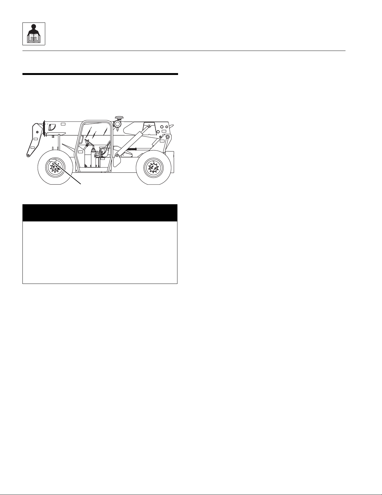
2.1 REPLACEMENT PARTS AND WARRANTY INFORMATION
Before ordering parts or initiating service inquiries, make
note of the machine serial number. The machine serial
number plate (1) is located at the left front corner of the
frame.
°
0
8
°
0
7
°
0
6
°
0
5
°
0
4
°
0
3
°
0
2
1
°
0
0
°
1
0°
4
E
U
Q
R
B
O
T
U
H
R
1
MX0030
NOTICE
The replacement of any part on this machine with any
other than JLG authorized replacement parts can
adversely affect the performance, durability, or safety
of the machine, and will void the warranty. JLG
disclaims liability for any claims or damages, whether
regarding property damage, personal injury or death
arising out of the use of unauthorized replacement
parts.
A warranty registration form must be filled out by the JLG
distributor, signed by the purchaser and returned to JLG
when the machine is sold and/or put into use.
Registration activates the warranty period and helps to
assure that warranty claims are promptly processed. To
guarantee full warranty service, verify that the distributor
has returned the business reply card of the warranty
registration form to JLG.
2.2
534D-9, 534D-10 & 544D
Page 15
General Information and Specifications
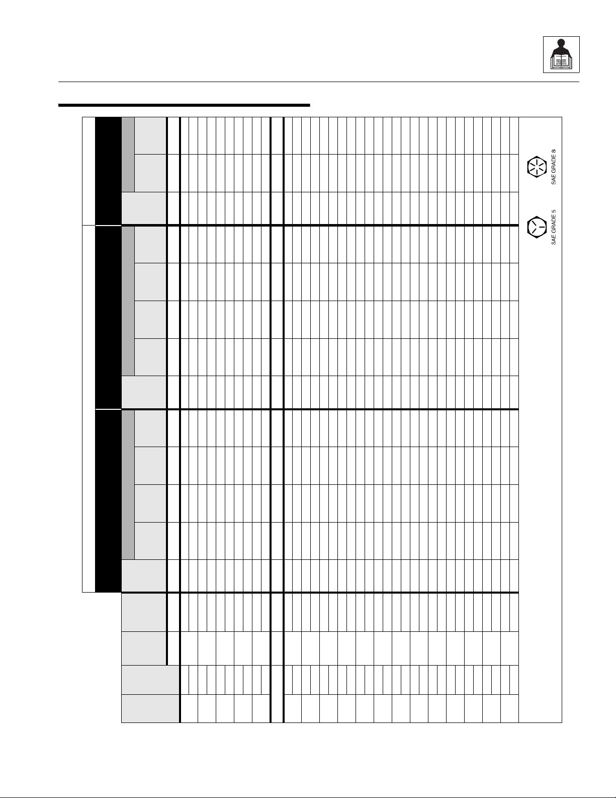
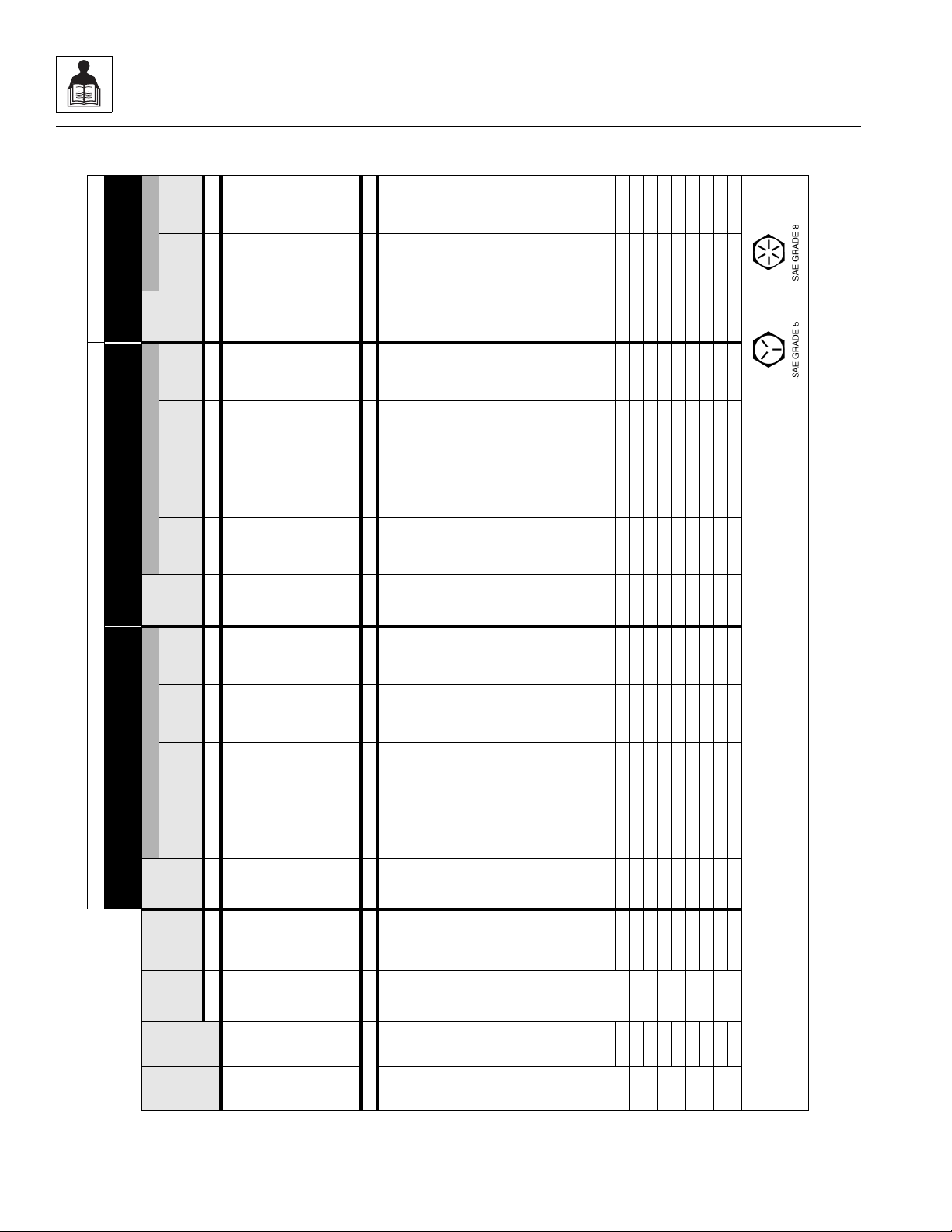
2.2 TORQUE CHARTS
WITH
PATCH
LOC-WEL
TORQUE
PATCH
LOC-WEL
WITHOUT
SOCKET HEAD
UNBRAKO 1960 SERIES
& SOCKET HEAD CAP SCREWS
SAE GRADE 8 BOLTS & GRADE 8 NUTS
LOAD
CLAMP
LOCTITE
LOCTITE
TORQUE
DRY OR
LOAD
CLAMP
242 OR
LUB
LOCTITE
271
262
263
2.2.1 ASTM Fastener Torque Chart (English)
271
242 OR
LOCTITE
262
LOCTITE
TORQUE
LUB
VALUES FOR ZINC PLATED / YELLOW CHROMATE FASTENERS ONLY UNPLATED CAP SCREWS
GRADE 2 NUTS
SAE GRADE 5 BOLTS &
DRY OR
CLAMP
TENSILE
BOLT
THDS.
263
LOCTITE
LOAD
AREA
STRESS
DIA.
PER
INCH
SIZE
IN SQ. IN. LB. IN-LB IN-LB IN-LB IN-LB LB. IN-LB. IN-LB IN-LB IN-LB LB. IN-LB IN-LB
0.00604 380 8 6 — — 540 12 9 — — — — —
40
0.1120
48 0.00661 420 9 7 — — 600 13 10 — — — — —632
4
0.00909 580 16 12 — — 820 23 17 — — — — —
0.1380
40 0.01015 610 18 13 — — 920 25 19 — — — — —832
0.01400 900 30 22 — — 1260 41 31 — — — — —
0.1640
36 0.01474 940 31 23 — — 1320 43 32 — — — — —1024
0.01750 1120 43 32 — — 1580 60 45 — — — — —
0.1900
32 0.02000 1285 49 36 — — 1800 68 51 — — — — —
0.0318 2020 96 75 — 105 2860 144 108 — 160 3180 160 168
20
0.2500
28 0.0364 2320 120 86 — 135 3280 168 120 — 185 3640 168 178
1/4
0.6060 38600 640 480 579 675 51500 900 680 687 990 60600 865 950
0.7630 42300 800 600 714 840 68700 1280 960 1030 1400 76300 1240 1365
0.9690 53800 1120 840 1009 1175 87200 1820 1360 1453 2000 96900 1750 1925
1.1550 64100 1460 1100 1322 1525 104000 2380 1780 1907 2625 115500 2320 2550
12 1.0730 59600 1240 920 1118 1300 96600 2000 1500 1610 2200 107300 1880 2070
6
1.3750
12 1.3150 73000 1680 1260 1506 1750 118100 2720 2040 2165 3000 131500 2440 2685
1-3/8
1.4050 78000 1940 1460 1755 2025 126500 3160 2360 2530 3475 140500 3040 3345
1.5000
6
1-1/2
12 1.5800 87700 2200 1640 1974 2300 142200 3560 2660 2844 3925 158000 3270 3600
Note: These torque values do not apply to cadmium plated fasteners.
0.0524 3340 17 13 16 19 4720 25 18 22 30 5240 25 28
0.0775 4940 30 23 28 35 7000 45 35 40 50 7750 45 50
0.1063 6800 50 35 45 55 9550 70 55 63 80 10630 70 77
0.1419 9050 75 55 68 85 12750 110 80 96 120 14190 110 120
0.1820 11600 110 80 98 120 16400 150 110 139 165 18200 155 170
0.2260 14400 150 110 135 165 20350 220 170 180 240 22600 210 231
0.3340 21300 260 200 240 285 30100 380 280 301 420 33400 365 400
0.4620 29400 430 320 386 475 41600 600 460 485 660 46200 585 645
IN SQ. IN. LB. FT-LB FT-LB FT-LB FT-LB LB. FT-LB FT-LB FT-LB FT-LB LB. FT-LB FT-LB
0.3125
0.3750
0.4375
0.5000
0.5625
0.6250
0.7500
18
24 0.0580 3700 19 14 17 21 5220 25 20 25 30 5800 27 30
16
24 0.0878 5600 35 25 32 40 7900 50 35 45 55 8780 50 55
14
20 0.1187 7550 55 40 50 60 10700 80 60 70 90 11870 75 82
13
20 0.1599 10700 90 65 80 100 14400 120 90 108 130 15990 115 127
12
18 0.2030 12950 120 90 109 135 18250 170 130 154 190 20300 165 182
11
18 0.2560 16300 170 130 153 190 23000 240 180 204 265 25600 220 242
10
16 0.3730 23800 300 220 268 330 33600 420 320 336 465 37300 400 440
5/16
3/8
7/16
1/2
9/16
5/8
3/4
9
0.8750
14 0.5090 32400 470 350 425 520 45800 660 500 534 725 50900 635 700
7/8
8
1.0000
12 0.6630 42200 700 530 633 735 59700 1000 740 796 1100 66300 915 1000
1
7
1.1250
12 0.8560 47500 880 660 802 925 77000 1440 1080 1155 1575 85600 1380 1520
1-1/8
1.2500
7
1-1/4
534D-9, 534D-10 & 544D
2.3
Page 16
General Information and Specifications
2.2.2 ASTM Fastener Torque Chart (Metric)
WITH
PATCH
LOC-WEL
TORQUE
PATCH
LOC-WEL
WITHOUT
SOCKET HEAD
UNBRAKO 1960 SERIES
CLAMP
LOCTITE
LOAD
242 OR
LOCTITE
271
262
TORQUE
LUB
263
DRY OR
LOCTITE
& SOCKET HEAD CAP SCREWS
SAE GRADE 8 BOLTS & GRADE 8 NUTS
VALUES FOR ZINC PLATED / YELLOW CHROMATE FASTENERS ONLY UNPLATED CAP SCREWS
LOAD
CLAMP
271
242 OR
LOCTITE
262
LOCTITE
TORQUE
LUB
GRADE 2 NUTS
SAE GRADE 5 BOLTS &
263
DRY OR
LOCTITE
2.4
LOAD
CLAMP
AREA
0.00604 380 .8 .8 — — 540 1.4 1.0 — — — — —
0.00909 580 1.8 1.4 — — 820 2.6 2.0 — — — — —
0.01400 900 3.4 2.4 — — 1260 4.6 3.4 — — — — —
40 0.01015 610 2.0 1.6 — — 920 2.8 2.2 — — — — —832
0.1640
36 0.01474 940 3.4 2.6 — — 1320 5 3.6 — — — — —1024
0.01750 1120 5 3.6 — — 1580 7 5 — — — — —
0.1900
32 0.02000 1285 6 4 — — 1800 8 6 — — — — —
STRESS
TENSILE
INSQ. IN.LB.N, mN, mN, mN, mLB.N, mN, mN, mN, mLB.N, mN, m
DIA.
BOLT
PER
THDS.
SIZE
0.1120
0.1380
40
48 0.00661 420 1.0 .8 — — 600 1.5 1.0 — — — — —632
INCH
4
0.0318 2020 11 8 — 12 2860 16 12 — 18 3180 18 19
20
0.2500
28 0.0364 2320 14 10 — 15 3280 19 14 — 2 1 3640 19 20
1/4
0.0524 3340 23 18 22 26 4720 34 24 30 41 5240 34 38
INSQ. IN.LB.N, mN, mN, mN, mLB.N, mN, mN, mN, mLB.N, mN, m
0.3125
18
24 0.0580 3700 26 19 23 28 5220 34 27 34 41 5800 37 41
5/16
0.0775 4940 41 31 38 47 7000 61 47 54 68 7750 61 68
16
0.3750
24 0.0878 5600 47 34 43 54 7900 68 47 61 75 8780 68 75
3/8
0.1063 6800 68 47 61 75 9550 95 75 85 108 10630 95 104
14
0.4375
20 0.1187 7550 75 54 68 81 10700 108 81 95 122 11870 102 111
7/16
0.1419 9050 102 75 92 115 12750 149 108 130 163 14190 149 163
13
0.5000
20 0.1599 10700 122 88 108 136 14400 163 122 146 183 15990 156 172
1/2
0.1820 11600 149 108 133 163 16400 203 149 188 224 18200 210 230
12
0.5625
18 0.2030 12950 163 122 148 183 18250 230 176 209 258 20300 224 247
9/16
0.2260 14400 203 149 183 224 20350 298 230 244 325 22600 285 313
11
0.6250
18 0.2560 16300 230 176 207 258 23000 325 244 277 359 25600 298 328
5/8
0.3340 21300 353 271 325 386 30100 515 380 408 569 33400 495 542
0.7500
10
3/4
16 0.3730 23800 407 298 363 447 33600 569 434 456 630 37300 542 597
0.4620 29400 583 434 523 644 41600 813 624 658 895 46200 793 874
9
0.8750
14 0.5090 32400 637 475 576 705 45800 895 678 724 983 50900 861 949
7/8
0.6060 38600 868 651 785 915 51500 1220 922 931 1342 60600 1173 1288
1.0000
8
1
12 0.6630 42200 949 719 858 997 59700 1356 1003 1079 1491 66300 1241 1356
0.7630 42300 1085 813 968 1139 68700 1735 1302 1396 1898 76300 1681 1851
1.1250
7
1-1/8
12 0.8560 47500 1193 895 1087 1254 77000 1952 1464 1566 2135 85600 1871 2061
0.9690 53800 1518 1139 1368 1593 87200 2468 1844 1970 27 12 96900 2373 2610
1.2500
7
1-1/4
12 1.0730 59600 1681 1247 1516 1763 96600 2712 2034 2183 29 83 107300 2549 2807
1.1550 64100 1979 1491 1792 2068 104000 3227 2413 2586 3559 115500 3145 3457
1.3750
6
1-3/8
12 1.3150 73000 2278 1708 2042 2373 118100 3688 2766 2935 4067 131500 3308 3640
1.4050 78000 2630 1979 2379 2745 126500 4284 3200 3430 4711 140500 4122 4535
1.5000
6
1-1/2
12 1.5800 87700 2983 2224 2676 3118 142200 4827 3606 3856 5322 158000 4433 4881
Note: These torque values do not apply to cadmium plated fasteners.
534D-9, 534D-10 & 544D
Page 17
General Information and Specifications
9
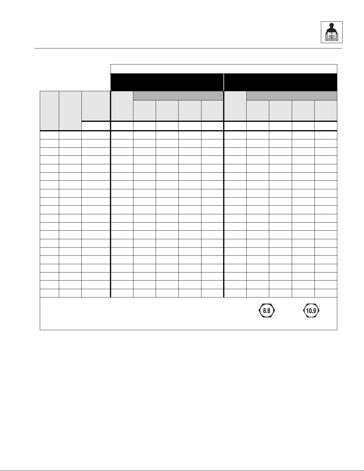
2.2.3 Metric Fastener Torque Chart
VALUES FOR ZINC PLATED / YELLOW CHROMATE FASTENERS ONLY
CLASS 8.8 METRIC BOLTS &
CLASS 8 METRIC NUTS
TORQUE
LUB
LOCTITE
262
LOCTITE
242 OR
271
CLAMP
SIZE PITCH
TENSILE
STRESS
AREA
CLAMP
LOAD
DRY OR
LOCTITE
263
sq. mm KN N, m N, m N, m N, m KN N, m N, m N, m N, m
3 .5 5.03 2.19 1.3 1.0 1.2 1.4 3.13 1.9 1.4 1.5 2.1
3.5 .6 6.78 2.95 2.1 1.6 1.9 2.3 4.22 3.0 2.2 2.4 3.3
4 .7 8.78 3.82 3.1 2.3 2.8 3.4 5.47 4.4 3.3 3.5 4.8
5 .8 14.2 6.18 6.2 4.6 5.6 6.8 8.85 8.9 6.6 7.1 9.7
6 1 20.1 8.74 11 7.9 9.4 12 12.5 15 11 12 17
7 1 28.9 12.6 18 13 16 19 18 25 19 20 28
81.2536.615.92519232822.837272940
10 1.5 58.0 25.2 50 38 45 55 36.1 72 54 58 79
12 1.75 84.3 36.7 88 66 79 97 52.5 126 95 101 139
14 2 115 50.0 140 105 126 154 71.6 200 150 160 220
16 2 157 68.3 219 164 197 241 97.8 313 235 250 344
18 2.5 192 83.5 301 226 271 331 119.5 430 323 344 473
20 2.5 245 106.5 426 320 383 469 152.5 610 458 488 671
22 2.5 303 132.0 581 436 523 639 189.0 832 624 665 915
24 3 353 153.5 737 553 663 811 220.0 1060 792 845 1170
27 3 459 199.5 1080 810 970 1130 286.0 1540 1160 1240 1690
30 3.5 561 244.0 1460 1100 1320 1530 349.5 2100 1570 1680 2310
33 3.5 694 302.0 1990 1490 1790 2090 432.5 2600 2140 2280 2860
36 4 817 355.0 2560 1920 2300 2690 509.0 3660 2750 2930 4020
42 4.5 1120 487.0 4090 3070 3680 4290 698.0 5860 4400 4690 6440
CLASS 10.9 METRIC BOLTS &
CLASS 10 METRIC NUTS
LOAD
DRY OR
LOCTITE
263
LUB
TORQUE
LOCTITE
262
LOCTITE
242 OR
271
Note: These torque values do not apply to cadmium plated fasteners.
534D-9, 534D-10 & 544D
METRIC CLASS 8.8 METRIC CLASS 10.
2.5
Page 18

General Information and Specifications
2.3 SPECIFICATIONS
2.3.1 Travel Speeds
534D-9 534D-10 544D
2 Wheel Drive 18 mph (29 km/h) 19 mph (30,5 km/h) 19 mph (30,5 km/h)
4 Wheel Drive 9 mph (14,4 km/h) 9.5 mph (15,3 km/h) 9.5 mph (15,3 km/h)
2.3.2 Hydraulic Cylinder Performance
Note: Machine with no attachment or load, engine at full throttle, hydraulic oil above 130° F (54° C) minimum, engine
at operating temperature.
FUNCTION APPROXIMATE TIMES (seconds)
534D-9 534D-10 544D
Boom Extend (max boom angle) 15.3 14.5 18.3
Boom Retract (max boom angle) 12.8 13.4 17.6
Boom Lift 11.4 10.8 11.9
Boom Lower 8.6 8.1 9.2
2.3.3 Electrical System
Battery:
Type, Rating 12 BCI, Negative (-) Ground, Maintenance Free
Quantity John Deere - 1 / Cummins - 2
Reserve Capacity 1,000 Cold Cranking Amps @ 0° F (-18° C)
Group/Series Group 31
Alternator (John Deere) 12V, 65 Amps
Alternator (Cummins) 12V, 95 Amps
2.6
534D-9, 534D-10 & 544D
Page 19

2.3.4 Engine Performance Specifications
a. John Deere
Description 534D-9 534D-10 544D
General Information and Specifications
Engine Make/Model John Deere
PE4045TF275
John Deere
PE4045TF275
John Deere
PE4045HF275
Displacement 276 in³ (4,5 liters) 276 in³ (4,5 liters) 276 in³ (4,5 liters)
Low Idle 800 rpm 800 rpm 800 rpm
High Idle 2400 rpm 2500 rpm 2200 rpm
Horsepower 110 HP (82 kW) @
2400 rpm
115 HP (86 kW) @
2500 rpm
125 HP (93 kW) @
2200 rpm
Peak Torque 289 lb-ft @1400 rpm 290 lb-ft @1400 rpm 376 lb-ft @1500 rpm
Fuel Delivery Fuel Injection Fuel Injection Fuel Injection
Air Cleaner Dry Type, Replaceable
Primary and Safety
Elements
Dry Type, Replaceable
Primary and Safety
Elements
Dry Type, Replaceable
Primary and Safety
Elements
b. Cummins
534D-9 / 534D-10 544D
Engine Make/Model Cummins QSB4.5 Cummins QSB4.5
Displacement 274 in
3
(4,5 liters) 274 in3 (4,5 liters)
Low Idle 1000 rpm 1000 rpm
High Idle 2500 rpm 2500 rpm
Horsepower 110 hp (82 Kw) @ 2500
rpm
Peak Torque 360 lb-ft (488 Nm) @
1500 rpm
130 hp (97 Kw) @ 2500
rpm
459 lb-ft (622 Nm) @
1500 rpm
Fuel Delivery Fuel Injection Fuel Injection
Air Cleaner Dry Type, Replaceable
Primary and Safety
Elements
534D-9, 534D-10 & 544D
Dry Type, Replaceable
Primary and Safety
Elements
2.7
Page 20

General Information and Specifications
2.3.5 Tires
Note: Standard wheel lug nut torque is 350-400 lb-ft (475-542 Nm).
Note: Pressures for Foam and Water/Calcium Chloride filled tires are for initial fill ONLY.
a. 534D-9
Size Tire Type Minimum Ply/
Star Rating
Pneumatic 70 psi (4,8 bar)
13.00 x 24 G - 2 Bias - 12 Ply
Foam - Approx. 542 lb (246 kg) 65 psi (4,5 bar)
Pneumatic 75 psi, (5,2 bar)
13.00 x 24 L-2 / G-2 Radial
Foam - Approx. 542 lb (246 kg) 75 psi (5,2 bar)
Pneumatic 70 psi (4,8 bar)
13.00 x 24 G - 3 Rock Bias - 12 Ply
Foam - Approx. 542 lb (246 kg) 65 psi (4,5 bar)
13.00 x 24 Solid
b. 534D-10
Size Tire Type Minimum Ply/
Star Rating
Pneumatic 70 psi (4,8 bar)
14.00 x 24 G - 2 Bias 12 ply
Foam - Approx. 720 lb (327 kg) 62 psi (4,2 bar)
Pneumatic 75 psi (5,2 bar)
14.00 x 24 L-2 / G-2 Radial
Foam - Approx. 720 lb (327 kg) 70 psi (4,8 bar)
Fill Type Pressure
Fill Type Pressure
14.00 x 24 G - 3 Rock Bias 12 ply
c. 544D
Size Tire Type Minimum Ply/
Star Rating
14.00 x 24 G - 2 Bias 12 ply
14.00 x 24 L-2 / G-2 Radial
14.00 x 24 G - 3 Rock Bias 12 ply
2.8
Pneumatic 70 psi (4,8 bar)
Foam - Approx. 720 lb (327 kg) 62 psi (4,2 bar)
Fill Type Pressure
Water/Calcium Chloride -
Approx. 623 lb (283 kg)
70 psi (4,8 bar)
Foam - Approx. 720 lb (327 kg) 62 psi (4,2 bar)
Water/Calcium Chloride -
Approx. 623 lb (283 kg)
75 psi (5,2 bar)
Foam - Approx. 720 lb (327 kg) 70 psi (4,8 bar)
Water/Calcium Chloride -
Approx. 623 lb (283 kg)
70 psi (4,8 bar)
Foam - Approx. 720 lb (327 kg) 62 psi (4,2 bar)
534D-9, 534D-10 & 544D
Page 21

General Information and Specifications
2.4 FLUID AND LUBRICANT CAPACITIES
Engine Crankcase Oil
Capacity w/Filter Change (John Deere) 15.5 quarts (14,6 liters)
Capacity w/Filter Change (Cummins) 11 quarts (10,4 liters)
Filter Capacity 1 quart (0,9 liters)
Oil Type 15W-40 CD
Fuel Tank
Capacity 40 gallons (151,4 liters)
Type of Fuel Low Sulfur Diesel #2
Cooling System
System Capacity (John Deere) 24.8 quarts (23,5 liters)
System Capacity (Cummins) 22 quarts (20,8 liters)
Type of Fluid 50/50 ethylene glycol & water
Front Axle
Differential Housing Capacity 19.6 quarts (18,5 liters)
Type of Fluid Mobilfluid 424
®
Tractor Hydraulic Fluid (ISO 46)
Rear Drive Hubs
Wheel End Capacity 1.5 quart (1,4 liters)
Type of Fluid Mobilfluid 424
®
Tractor Hydraulic Fluid (ISO 46)
Hydraulic System
System Capacity - 534D-9, 534D-10 47 gallons (178 liters)
System Capacity - 544D 50 gallons (189 liters)
Reservoir Capacity 30 gallons (113,5 liters)
Type of Fluid Mobilfluid 424
®
Tractor Hydraulic Fluid (ISO 46)
534D-9, 534D-10 & 544D
2.9
Page 22
General Information and Specifications
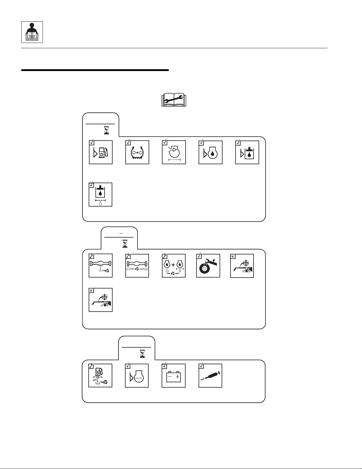
2.5 SERVICE AND MAINTENANCE SCHEDULES
2.5.1 10, 1st 50 & 50 Hour
EVERY
10
Check Fuel
Level
Check Hydraulic
Return Filter
Indicator
50
Change
Axle Oil
Check Boom
Chain Tension
(544D)
Check Tire
st
1
Change Wheel
Pressure
End Oil
Air Filter
Restriction
Indicator
Change Engine
Oil & Filter
Check Engine
Oil Level
L
B
/F
T
(
N
m
Check Wheel
Lug Nut
Torque
Check Hydraulic
Oil Level
)
Check Boom
Cable Tension
(534D-9 & 534D-10)
2.10
Drain Fuel/
Water
Separator
EVERY
50
Check Engine
Coolant Level
Check
Battery
Lubrication
Schedule
MX0080
534D-9, 534D-10 & 544D
Page 23
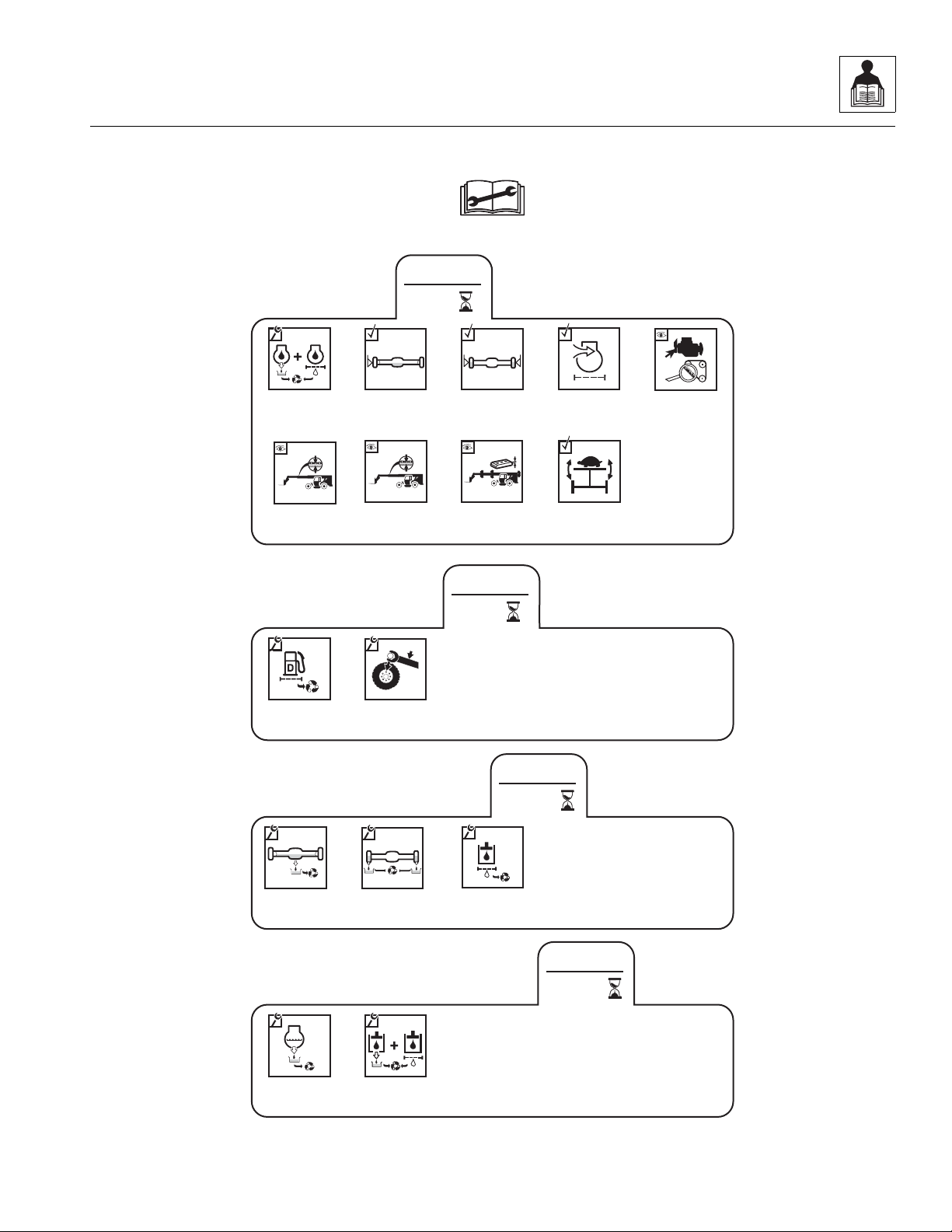
2.5.2 250, 500, 1000 & 1500 Hour
General Information and Specifications
EVERY
250
Change Engine
Oil and
Filter*
Check Boom
Cable Tension
(534D-9 & 534D-10)
Change Fuel
Filter
Check Front
Axle
Oil Level
Check Boom
Chain Tension
(544D)
L
B
/
F
T
(
N
m
)
Check Wheel
Lug Nut
Torque
Check Front &
Rear Wheel
End Oil Levels
Check Boom
Bearing
Pads
EVERY
500
EVERY
1000
Air Filter
Vacuator
Valve
Check
Rear Axle
Stabilization
Check
Fan Belt
534D-9, 534D-10 & 544D
Change Front
Axle Oil
Change
Engine Coolant
Change Front &
Rear Wheel
End Oil
Change
Hydraulic
Fluid & Filters
Change
Hydraulic Tank
Breather
EVERY
1500
MX0090
2.11
Page 24
General Information and Specifications
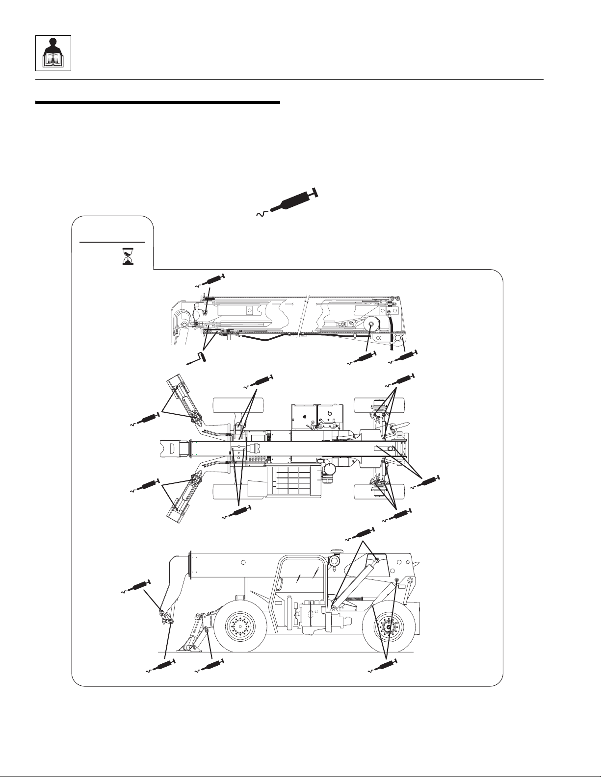
2.6 LUBRICATION SCHEDULES
2.6.1 534D-9, 534D-10
a. 50 Hour
EVERY
50
MYSTIK TETRIMOLY
(NLGI 2 GC-LB)
2.12
OX03412
534D-9, 534D-10 & 544D
Page 25
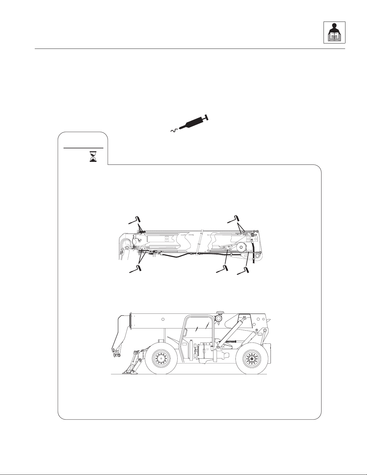
b. 250 Hour
General Information and Specifications
EVERY
250
MYSTIK TETRIMOLY
(NLGI 2 GC-LB)
534D-9, 534D-10 & 544D
OX03512
2.13
Page 26
General Information and Specifications
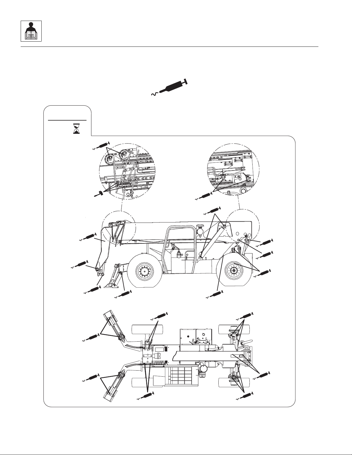
2.6.2 544D
a. 50 Hour
EVERY
50
MYSTIK TETRIMOLY
(NLGI 2 GC-LB)
2.14
MX00512
534D-9, 534D-10 & 544D
Page 27
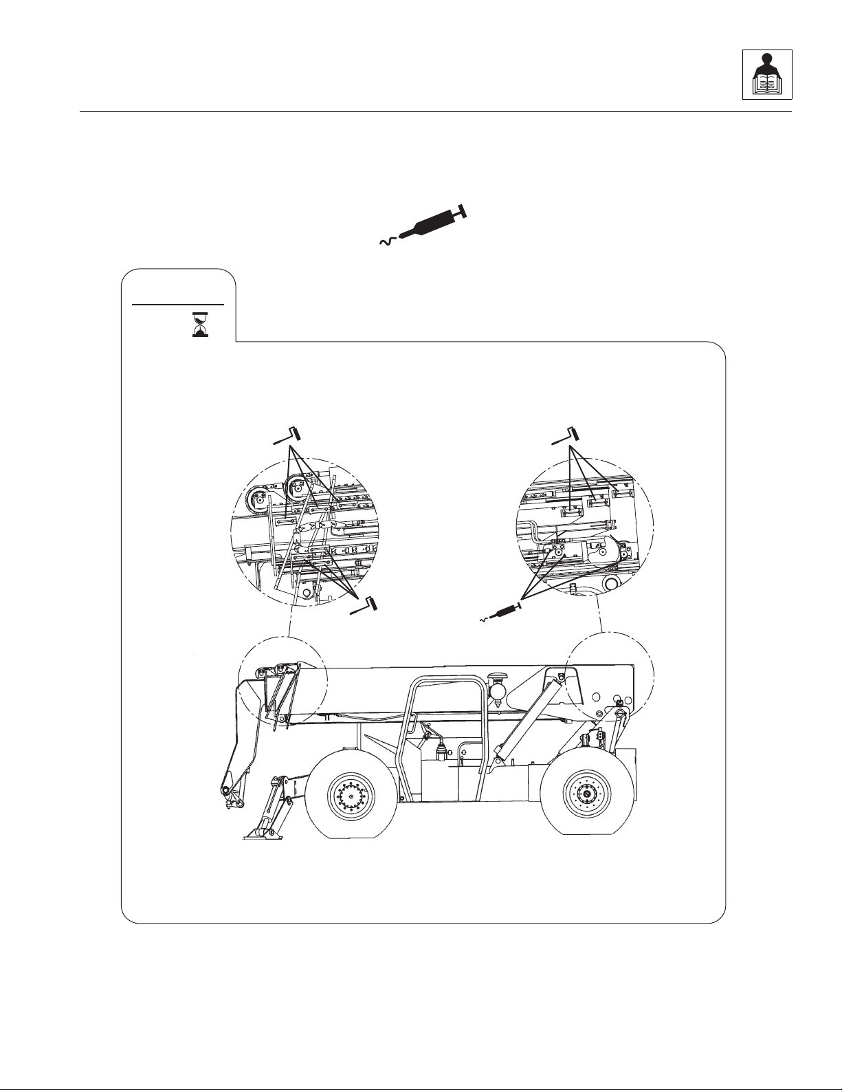
b. 250 Hour
EVERY
50
General Information and Specifications
MYSTIK TETRIMOLY
(NLGI 2 GC-LB)
534D-9, 534D-10 & 544D
MX00712
2.15
Page 28

General Information and Specifications
This Page Intentionally Left Blank
2.16
534D-9, 534D-10 & 544D
Page 29

Section 3
Boom
Contents
PARAGRAPH TITLE PAGE
3.1 Boom System Component Terminology 534D-9, 534D-10 . . . . . . . . . . . . . . . . . 3.3
3.2 Boom System - Three Section . . . . . . . . . . . . . . . . . . . . . . . . . . . . . . . . . . . . . . . . 3.4
3.2.1 Boom System Operation . . . . . . . . . . . . . . . . . . . . . . . . . . . . . . . . . . . . . . 3.4
3.3 Boom Maintenance - Three Section (Complete Removal). . . . . . . . . . . . . . . . . . 3.4
3.3.1 Boom Removal . . . . . . . . . . . . . . . . . . . . . . . . . . . . . . . . . . . . . . . . . . . . . 3.4
3.3.2 Second & Third Boom Section Removal. . . . . . . . . . . . . . . . . . . . . . . . . . 3.5
3.3.3 Third Boom Section & Push Beam Removal . . . . . . . . . . . . . . . . . . . . . . 3.5
3.3.4 Third Boom Section Installation . . . . . . . . . . . . . . . . . . . . . . . . . . . . . . . . 3.6
3.3.5 Extend/Retract Cylinder and Push Beam Assembly and Installation . . . . 3.7
3.3.6 Second & Third Boom Section Installation . . . . . . . . . . . . . . . . . . . . . . . . 3.7
3.4 Boom Maintenance - Three Section (Individual Section Removal) . . . . . . . . . . 3.9
3.4.1 Push Beam and Third Boom Section Removal. . . . . . . . . . . . . . . . . . . . . 3.9
3.4.2 Second Boom Section Removal . . . . . . . . . . . . . . . . . . . . . . . . . . . . . . . . 3.10
3.4.3 Second and Third Boom Section Removal . . . . . . . . . . . . . . . . . . . . . . . . 3.10
3.4.4 Second Boom Section Installation . . . . . . . . . . . . . . . . . . . . . . . . . . . . . . 3.11
3.4.5 Third Boom Section Installation . . . . . . . . . . . . . . . . . . . . . . . . . . . . . . . . 3.11
3.5 Boom Cables - Three Section . . . . . . . . . . . . . . . . . . . . . . . . . . . . . . . . . . . . . . . . 3.12
3.5.1 General Cable Information . . . . . . . . . . . . . . . . . . . . . . . . . . . . . . . . . . . . 3.12
3.5.2 Cable Adjustments . . . . . . . . . . . . . . . . . . . . . . . . . . . . . . . . . . . . . . . . . . 3.12
3.5.3 Retract Cable Removal . . . . . . . . . . . . . . . . . . . . . . . . . . . . . . . . . . . . . . . 3.13
3.5.4 Retract Cable Installation . . . . . . . . . . . . . . . . . . . . . . . . . . . . . . . . . . . . . 3.14
3.5.5 Extend Cable Removal . . . . . . . . . . . . . . . . . . . . . . . . . . . . . . . . . . . . . . . 3.14
3.5.6 Extend Cable Installation . . . . . . . . . . . . . . . . . . . . . . . . . . . . . . . . . . . . . 3.15
3.5.7 Tilt and Auxiliary Circuit Hose Removal/Installation . . . . . . . . . . . . . . . . . 3.16
3.5.8 Hose Removal. . . . . . . . . . . . . . . . . . . . . . . . . . . . . . . . . . . . . . . . . . . . . . 3.16
3.5.9 Hose Installation . . . . . . . . . . . . . . . . . . . . . . . . . . . . . . . . . . . . . . . . . . . . 3.16
3.6 Auxiliary Electric Cable - Three Section . . . . . . . . . . . . . . . . . . . . . . . . . . . . . . . . 3.17
3.6.1 Electrical Wire Data . . . . . . . . . . . . . . . . . . . . . . . . . . . . . . . . . . . . . . . . . 3.17
3.6.2 Electrical Cable Removal . . . . . . . . . . . . . . . . . . . . . . . . . . . . . . . . . . . . . 3.17
3.6.3 Electrical Cable Installation. . . . . . . . . . . . . . . . . . . . . . . . . . . . . . . . . . . . 3.17
3.7 Extend/Retract Cylinder Removal and Installation - Three Section . . . . . . . . . . 3.18
3.7.1 Extend/Retract Cylinder Removal . . . . . . . . . . . . . . . . . . . . . . . . . . . . . . . 3.18
3.7.2 Extend/Retract Cylinder Installation . . . . . . . . . . . . . . . . . . . . . . . . . . . . . 3.19
3.8 Boom System Component Terminology 544D . . . . . . . . . . . . . . . . . . . . . . . . . . . 3.20
3.9 Boom System - Four Section . . . . . . . . . . . . . . . . . . . . . . . . . . . . . . . . . . . . . . . . . 3.21
3.9.1 Boom System Operation . . . . . . . . . . . . . . . . . . . . . . . . . . . . . . . . . . . . . . 3.21
534D-9, 534D-10 & 544D
3.1
Page 30

Boom
3.10 Boom Maintenance - Four Section (Complete Removal). . . . . . . . . . . . . . . . . . . 3.21
3.10.1 Boom Removal . . . . . . . . . . . . . . . . . . . . . . . . . . . . . . . . . . . . . . . . . . . . . 3.21
3.10.2 Extend/Retract Cylinder Removal . . . . . . . . . . . . . . . . . . . . . . . . . . . . . . . 3.21
3.10.3 Tilt Cylinder Removal . . . . . . . . . . . . . . . . . . . . . . . . . . . . . . . . . . . . . . . . 3.22
3.10.4 Second, Third & Fourth Boom Section Removal. . . . . . . . . . . . . . . . . . . . 3.22
3.10.5 Third & Fourth Boom Section Removal. . . . . . . . . . . . . . . . . . . . . . . . . . . 3.23
3.10.6 Fourth Boom Section Removal . . . . . . . . . . . . . . . . . . . . . . . . . . . . . . . . . 3.23
3.10.7 Hydraulic Sub-Assembly . . . . . . . . . . . . . . . . . . . . . . . . . . . . . . . . . . . . . . 3.24
3.10.8 Fourth Boom Section Install . . . . . . . . . . . . . . . . . . . . . . . . . . . . . . . . . . . 3.25
3.10.9 Third Boom Section Install . . . . . . . . . . . . . . . . . . . . . . . . . . . . . . . . . . . . 3.25
3.10.10 Second Boom Section Install . . . . . . . . . . . . . . . . . . . . . . . . . . . . . . . . . . 3.26
3.10.11 First Boom Section Install . . . . . . . . . . . . . . . . . . . . . . . . . . . . . . . . . . . . . 3.27
3.10.12 Boom Assembly Installation . . . . . . . . . . . . . . . . . . . . . . . . . . . . . . . . . . . 3.28
3.11 Boom Maintenance - Four Section (Individual Section Removal) . . . . . . . . . . . 3.28
3.11.1 Fourth Boom Section Removal . . . . . . . . . . . . . . . . . . . . . . . . . . . . . . . . . 3.29
3.11.2 Third Boom Section Removal . . . . . . . . . . . . . . . . . . . . . . . . . . . . . . . . . . 3.30
3.11.3 Second Boom Section Removal . . . . . . . . . . . . . . . . . . . . . . . . . . . . . . . . 3.30
3.11.4 Second, Third and Fourth Boom Section Removal. . . . . . . . . . . . . . . . . . 3.31
3.11.5 Second Boom Section Installation . . . . . . . . . . . . . . . . . . . . . . . . . . . . . . 3.31
3.11.6 Third Boom Section Installation . . . . . . . . . . . . . . . . . . . . . . . . . . . . . . . . 3.31
3.11.7 Fourth Boom Section Installation . . . . . . . . . . . . . . . . . . . . . . . . . . . . . . . 3.32
3.12 Boom Extend and Retract Chains - Four Section . . . . . . . . . . . . . . . . . . . . . . . . 3.32
3.12.1 Boom Chain Inspection. . . . . . . . . . . . . . . . . . . . . . . . . . . . . . . . . . . . . . . 3.32
3.12.2 Inspection Guidelines . . . . . . . . . . . . . . . . . . . . . . . . . . . . . . . . . . . . . . . . 3.33
3.12.3 Adjusting Extend Chains. . . . . . . . . . . . . . . . . . . . . . . . . . . . . . . . . . . . . . 3.35
3.12.4 Adjusting Retract Chains. . . . . . . . . . . . . . . . . . . . . . . . . . . . . . . . . . . . . . 3.35
3.12.5 Retract Chain Removal . . . . . . . . . . . . . . . . . . . . . . . . . . . . . . . . . . . . . . . 3.36
3.12.6 Retract Chain Installation . . . . . . . . . . . . . . . . . . . . . . . . . . . . . . . . . . . . . 3.36
3.12.7 Extend Chain Removal . . . . . . . . . . . . . . . . . . . . . . . . . . . . . . . . . . . . . . . 3.37
3.12.8 Extend Chain Installation . . . . . . . . . . . . . . . . . . . . . . . . . . . . . . . . . . . . . 3.37
3.13 Boom Section Separation Adjustment - Four Section. . . . . . . . . . . . . . . . . . . . . 3.38
3.14 Hydraulic Sub-Assembly Removal/Installation - Four Section . . . . . . . . . . . . . . 3.38
3.14.1 Hydraulic Sub-Assembly Removal . . . . . . . . . . . . . . . . . . . . . . . . . . . . . . 3.38
3.14.2 Assembling the Hydraulic Sub-Assembly . . . . . . . . . . . . . . . . . . . . . . . . . 3.39
3.14.3 Hydraulic Sub-Assembly Installation. . . . . . . . . . . . . . . . . . . . . . . . . . . . . 3.39
3.15 Boom Wear Pads. . . . . . . . . . . . . . . . . . . . . . . . . . . . . . . . . . . . . . . . . . . . . . . . . . . 3.41
3.15.1 Wear Pad Inspection . . . . . . . . . . . . . . . . . . . . . . . . . . . . . . . . . . . . . . . . . 3.41
3.15.2 Boom Wear Pad Replacement . . . . . . . . . . . . . . . . . . . . . . . . . . . . . . . . . 3.41
3.15.3 Boom Wear Pad Lubrication . . . . . . . . . . . . . . . . . . . . . . . . . . . . . . . . . . . 3.41
3.16 Quick Switch Assembly . . . . . . . . . . . . . . . . . . . . . . . . . . . . . . . . . . . . . . . . . . . . . 3.42
3.16.1 Disconnecting from an Attachment . . . . . . . . . . . . . . . . . . . . . . . . . . . . . . 3.42
3.16.2 Connecting to an Attachment . . . . . . . . . . . . . . . . . . . . . . . . . . . . . . . . . . 3.42
3.16.3 Quick Switch Removal . . . . . . . . . . . . . . . . . . . . . . . . . . . . . . . . . . . . . . . 3.42
3.16.4 Quick Switch Installation . . . . . . . . . . . . . . . . . . . . . . . . . . . . . . . . . . . . . . 3.42
3.17 Forks. . . . . . . . . . . . . . . . . . . . . . . . . . . . . . . . . . . . . . . . . . . . . . . . . . . . . . . . . . . . . 3.43
3.18 Troubleshooting . . . . . . . . . . . . . . . . . . . . . . . . . . . . . . . . . . . . . . . . . . . . . . . . . . . 3.44
3.2
534D-9, 534D-10 & 544D
Page 31

3.1 BOOM SYSTEM COMPONENT TERMINOLOGY 534D-9, 534D-10
The following illustrations identify the components that
are referred to throughout this section.
SECOND
BOOM
THIRD
BOOM
SECTION
SECTION
ATTACHMENT
TILT
CYLINDER
EXTEND CABLES
(inside boom)
FIRST
BOOM
SECTION
Boom
ATTACHMENT
QUICK SWITCH
EXTEND/RETRACT
CYLINDER
(inside boom)
HOSE
SHEAVE
(inside boom)
RETRACT
CABLES
(inside boom)
MX0110
534D-9, 534D-10 & 544D
3.3
Page 32

Boom
3.2 BOOM SYSTEM - THREE SECTION
3.2.1 Boom System Operation
The three section boom consists of the first, second and
third assemblies with second and third section extend
cables, and a single second and third section retract
cable.
As the extend/retract cylinder, which is anchored at the
rear of the first boom section, and the front of the push
beam begins to extend, it forces the second and third
boom sections out of the first boom section.
The boom sections are connected by extend and retract
cables. These cables are routed around sheaves on the
front of the push beam and the rear of the second boom
section. As the extend/retract cylinder is forced out
hydraulically, the second and third boom sections are
pulled out by the extend cables.
As hydraulic pressure is applied to the retract port on the
extend/retract cylinder, the retract cable pulls the second
and third boom sections back into the first boom section.
This mechanical linkage formed by the cables and
supporting hardware, extends and retracts the second
and third boom sections at the same rate.
The boom section lifts and lowers via action of the lift
cylinder.
3.3 BOOM MAINTENANCE - THREE SECTION (COMPLETE REMOVAL)
These instructions must be completed in sequence. The
second and third boom sections are removed from the
first boom section.The third boom section is removed
from the second boom section.
Before beginning, conduct a visual inspection of the
machine and work area, and review the task about to be
undertaken. Read, understand and follow these
instructions.
WARNING
NEVER weld or drill the boom unless approved in
writing by JLG. The structural integrity of the boom
will be impaired if subjected to any repair involving
welding or drilling.
3.3.1 Boom Removal
While the boom sections can be separated from each
other on the machine, JLG recommends against this
procedure. It is much safer, more efficient and more costeffective to remove the complete boom assembly from
the machine and place it on suitable supports for
separation. Work can then progress at a normal working
height.
Note: When removing a complete boom assembly use
a hoist or crane with a minimum lift capacity of 6000 lbs.
1. Remove any attachment from the quick switch
assembly. Refer to Section 3.16.1, “Disconnecting
from an Attachment.”
2. Park the machine on a hard, level surface, fully
retract the boom, level the boom assembly, place the
transmission control lever in (N) NEUTRAL, engage
the park brake and shut the engine OFF.
3. Place a Do Not Operate Tag on both the ignition key
switch and the steering wheel, stating that the
machine should not be operated.
4. Open the engine cover. Allow the system fluids to
cool.
5. Remove the battery negative (-) cable from the
battery negative (-) terminal.
6. Place a sling around the first boom section at the
balance point.
7. Take the weight off the boom assembly.
8. Label. disconnect and cap all hydraulic hoses
attached to the boom. Cap all fittings and openings
to keep dirt & debris from entering the hydraulic
system.
9. Label, disconnect any electrical cables if equipped.
10. Remove the pin from the rod end of the
compensation cylinder being careful not to drop the
cylinder. Lower the cylinder to a secure position.
11. Remove the pin from the rod end of both lift cylinders
being careful not to drop the cylinder. Lower the
cylinder to a secure position.
12. Confirm that the boom assembly is balanced with
the sling and remove the boom assembly pivot pin.
13. Lift the boom assembly from the machine and lower
onto suitable supports
3.4
534D-9, 534D-10 & 544D
Page 33

3.3.2 Second & Third Boom Section Removal
1. Set the complete boom on level ground and by
repositioning the slings turn boom over on to the top
side. Set the complete boom on suitable stands to
begin tear down.
Note: With the complete boom setting upside down, the
removal and replacing of each boom section, tilt cylinder,
hoses, extend and retract cables and push beam are
made much easier.
2. Remove all wear pads, shims and backing plates
from the front inside of the first boom section. Label
and tag each set of wear pads being removed.
MX0120
3
3. Loosen the hose take-up brackets (1) on the bottom
front of the first boom section. Disconnect both tilt
hoses and both auxiliary hoses (2) inside the boom,
below the take-up brackets.Plug the hose ends and
cap the tube ends to prevent dirt and debris from
entering the hydraulic system.
Note: If the machine is equipped with auxiliary
hydraulics, separate the plug at the hose take-up area.
4. Loosen the lock-nut and jam-nut (3) on the retract
cable at the front of the first boom section. Loosen
and remove the bolts holding the retract cable
adjusting block.
1
2
Boom
4
5
MX0130
5. Remove the lock-nuts and jam-nuts (4) from the
extend cables at the rear of the boom assembly.
6. Label, disconnect and cap the extend/retract hoses
(5) from the cylinder. Cap all fittings and openings to
prevent dirt and debris from entering the hydraulic
system.
7. Remove the extend/retract cylinder mounting pin,
hose guards and strong back from the rear of the
boom assembly.
8. Place a sling around the second boom section, lift
and slowly pull the second and third boom section
approximately half way out of the first boom section.
Lower the second and third boom sections onto a
suitable support.
9. Relocate the sling or using two slings for better
stability, balance the two boom sections and slowly
pull them out of the first boom section being careful
not to damage the hydraulic hoses or cables. Lower
the second and third boom sections onto suitable
supports.
534D-9, 534D-10 & 544D
3.3.3 Third Boom Section & Push Beam Removal
1. Remove all wear pads, shims from the front inside of
the second boom section. Label and tag each set of
wear pads being removed
2. Label, disconnect and cap the tilt circuit hoses (6)
from the tilt cylinder at the front of the third boom
section. Label, disconnect and cap the auxiliary
circuit hoses from the quick disconnect fittings at the
front of the third boom section. Cap all fittings and
openings to prevent dirt and debris from entering the
hydraulic system.
3.5
Page 34

Boom
3. Loosen and remove all extend cable sheave
components from the front of the pivot beam.
4. Pull the extend cables free of the sheave brackets
and lay them on the boom.
6
8
7
MX0140
3.3.4 Third Boom Section Installation
Note: During reassembly use Loctite 242® on all bolt
threads and use Loctite 545
Note: Shim all wear pads to 1/16” of a tight fit. You may
have to final adjust the wear pads after the boom
assembly is installed on the machine and hydraulic
power is available.
Note: Coat the interior of all bushings and sheaves with
Mystik Tetrimoly Grease prior to the installation of pins
and bushings. Wear pads and slide areas must be
lubricated with Mystik Tetrimoly Grease or an equivalent.
1. Place the third boom section upside down on
suitable supports.
®
on all hydraulic fittings
10
9
5. At the rear of the boom, loosen and remove all
retract cable sheave components and the hydraulic
hose rollers and components (7).
6. Loosen and remove all push beam pins (8).
7. Pull the push beam free from the front of the third
boom section.
8. Place the hydraulic hoses inside the third boom
section.
9. Place a sling around the third boom section, lift and
slowly pull the third boom section approximately half
way out of the second boom section. Lower the third
boom section onto a suitable support.
10. Relocate the sling or using two slings for better
stability, balance the third boom section and slowly
pull the third boom section out of the second boom
section. Lower the third boom section onto suitable
supports.
Note: Before reassembly of the boom, check the bores,
pins and bushings for damage. Repair as needed. Also
check the diameters of the pins and bushings.
MX0150
2. Install the wear pads and spacers on the bottom and
both sides at the rear of the third boom section. For
ease of installation DO NOT install the top wear
pads at this time.
3. Install the single retract cable and the double extend
cables to the bracket (9) at the rear of the third boom
section.
4. Install the tilt circuit hoses, auxiliary circuit hoses
and if equipped, the electrical cables and brackets
inside protected areas.
5. Install the hose brackets (10) in place at the front of
the third boom section.
6. Lubricate wear pad paths and lay the tilt hoses,
auxiliary hoses, cables and if equipped, electrical
cable inside the third boom section to protect against
being damaged when installing the third boom
section into the second boom section.
3.6
534D-9, 534D-10 & 544D
Page 35

Boom
7. Connect the auxiliary hoses to the quick disconnects
on the side of the boom head. Connect the electrical
cable to the plug mounted below the auxiliary quick
disconnects if equipped.
8. Install the tilt cylinder in the boom head, install the
mounting pin and keeper bolt, locking the mounting
pin and tilt cylinder into position.
3.3.5 Extend/Retract Cylinder and Push Beam Assembly and Installation
1. Install the extend/retract cylinder (1) into the push
beam.
2. Install the mounting pin and hardware (2) at the
extend/retract cylinder rod eye.
3. Install the push beam assembly (3) through the front
of the third boom section leaving the sheave bracket
exposed for accessibility.
4. Guide the threaded end of the extend cables through
the sheave bracket.
Note: The extend cable will not feed through sheave
bracket with the sheave installed.
5. Lay the cables over the boom head and complete
the sheave assembly installation; i.e. sheaves, pins,
lube system and wear pad.
6. Guide the cable around the sheave and install the
cable guide and guide bar.
11. Set the third boom section onto a suitable support
and reset the sling under the boom head of the third
boom section. Carefully slide the third boom section
into the second boom section.
12. Install the push beam (3) fully into the second boom
section, lining up the mounting pin bores at the rear
of the second boom section.
13. Install the push beam mounting pins and locking
hardware (4).
14. Leave 6 in - 8 in (152 mm - 203 mm) of the third
boom section out to be able to install the wear pads
in the front of the second boom section.
15. With the sling still under boom head, install the wear
pads and spacers in the front of the second boom
section.
16. Install the top wear pads and spacers on the top rear
of the third boom section.
17. Install the wear pads and spacers on the bottom and
both sides at the rear of the second boom section.
For ease of installation DO NOT install the top wear
pads at this time.
18. Lubricate wear pads, inside sheaves, bores and pins
during assembly.
3
2
1
7. With the push beam installed in the third boom
section, the third boom section and push beam are
ready to be installed into the second boom section.
8. Place the second boom section upside down on
suitable supports.
9. Lubricate the inside second boom section on area’s
where the third boom section wear pads will slide.
10. Using a suitable sling, balance the third boom
section and carefully slide 3 ft - 4 ft (0,9 m - 1,22 m)
into the front of the second boom section.
534D-9, 534D-10 & 544D
MX0170
MX0160
3
4
3.3.6 Second & Third Boom Section Installation
1. Place the first boom section upside down on suitable
supports.
2. Lubricate the inside first boom section on area’s
where the second boom section wear pads will slide.
3. Using a suitable sling, balance the second and third
boom sections and carefully slide
3 ft - 4 ft (0,9 m - 1,22 m)into the front of the first
boom section.
3.7
Page 36

Boom
4. Set the second and third boom sections onto a
suitable support and reset the sling under the boom
head of the third boom section.
5. Carefully slide the two boom sections into the first
boom section. Leave 6 in - 8 in (152 mm - 203 mm)
in of the two boom sections out to be able to install
the wear pad block and the wear pads in the front of
the first boom section
6. Install the hose take-up assembly (5) components at
the front of the first boom section.
7. Install the retract cable adjusting block (6). Install the
retract cable. Do Not tighten the retract cable.
8. Install the wear pad block to the front inside of the
first boom section. Use Loctite 242
®
and torque the
wear pad block mounting bolts to 265-290 lb-ft
(359 - 393 Nm).
9. Install the wear pads, spacers and shims at the front
of the first boom section. Use Loctite 242
®
and
torque the wear pad mounting bolts to 68-78 lb-ft
(92 - 106 Nm).
17. On the bottom side of the first boom section install
the hose clamps for the tilt and auxiliary circuit
hoses.
Note: Do Not tighten clamps at this point.
18. At the area between the hose take-up bracket to the
first hose clamp, adjust the hoses to form a 4 in
(102 mm) partial loop between the bottom of the first
boom section to the bottom of the hoses (10).
19. Tighten all hose clamps.
8
9
7
8
5
6
10
MX0180
10. Place the strong back (7) in place at the rear of the
first boom section and install the extend/retract
cylinder mounting pin, spacers and retaining clips.
11. Measure the space between the top and bottom of
the strong back (8) and the inside of the first boom
section and shim as needed.
12. Install and torque the strong back mounting bolts.
13. Install the extend cables, springs, washers and lock
nuts into the strong back (9).
14. Tighten the extend cables adjusting nuts until the
gap between the cable flat washer and strong back
is 1/32 in to 1/16 in (0,79 mm - 1,57 mm). Gap for
both washers should be equal.
Note: When adjusting cables, make sure the cables are
not turning.
MX0190
15. Torque the cable jam nuts to 100 lb-ft (135 Nm).
16. Install the extend/retract hoses.
3.8
534D-9, 534D-10 & 544D
Page 37

3.4 BOOM MAINTENANCE - THREE SECTION (INDIVIDUAL SECTION REMOVAL)
These general instructions help with the removal of
individual boom sections with the boom still mounted on
the machine. Safe practices and common sense must be
followed when removing boom sections.
Before beginning, conduct a visual inspection of the
machine and work area, and review the task about to be
undertaken. Read, understand and follow these
instructions taking into consideration your particular
situation.
For more detailed instructions, see Section 3.3, “Boom
Maintenance - Three Section (Complete Removal).”
3.4.1 Push Beam and Third Boom Section
Removal
1. Park the machine on a firm, level surface, fully
retract the boom, lower the boom to a level position,
place the transmission control lever in (N)
NEUTRAL, engage the park brake and shut the
engine OFF.
2. Place a Do Not Operate Tag on both the ignition key
switch and the steering wheel, stating that the
machine should not be operated.
3. Open the engine cover. Allow the system fluids to
cool.
4. Remove the battery negative (-) cable from the
battery negative (-) terminal.
Note: When removing a boom section(s), use a lifting
device with a sufficient lift capacity. (A complete three
section boom assembly weighs approximately 5700 lbs.)
5. Label, disconnect and cap all hydraulic hoses
attached at the tilt cylinder. Cap all fittings and
openings to keep dirt and debris from entering the
hydraulic system.
6. Remove the tilt cylinder from the third boom section.
7. Disconnect and cap the tilt hoses attached at the
bulkhead bracket. Disconnect and cap the auxiliary
hoses attached at the bulkhead bracket if equipped.
8. Remove the bulkhead brackets (1).
9. Remove the guide plate and bar (2) from the top
front of the push beam.
Boom
2
1
10. Release tension from the hoses on the hose take-up
bracket (3).
11. Label, disconnect and cap all hydraulic hoses
attached at the take-up bracket (4). Cap all fittings
and openings to keep dirt and debris from entering
the hydraulic system.
12. If equipped, label, loosen and separate all electrical
cables at the take-up bracket.
13. Remove the take-up brackets (5).
14. Loosen and remove the jam nuts on the retract cable
(6) at the bottom of the first boom section.
15. Label, disconnect and cap both hydraulic hoses (7)
attached to the extend/retract cylinder. Cap all
fittings and openings to keep dirt and debris from
entering the hydraulic system.
16. Loosen and remove the jam nuts on the two extend
cables (8) at the strong back.
17. Remove the pin (9) holding the extend/retract
cylinder at the strong back.
18. Loosen and remove the bolts holding the strong
back to the rear of the first boom section. Remove
the strong back.
19. Remove the two pins (10) holding the push beam at
the rear of the second boom section.
20. Loosen and remove the wear pads from the front of
the second boom section. Note the location of the
wear pads, mounting bolts and number of shims
from each location.
21. Loosen and remove the wear pads from the top rear
and one side of the third boom section. Note the
location of the wear pads, mounting bolts and
number of shims from each location.
22. Remove hose guide (11) from the rear of the second
boom section.
6
MX1370
5
3
4
534D-9, 534D-10 & 544D
3.9
Page 38

Boom
10
11
8
9
7
MX1380
23. Slowly pull the push beam out of the front of the third
boom section. The extend cables will come out along
with the push beam.
24. When the head of the push beam is out of the third
boom section, stop and pull the extend cables the
remaining of the way out over the cable sheaves of
the push beam.
25. Slowly pull the push beam free of the machine and
place on the ground or suitable support.
Note: The extend/retract hydraulic cylinder can be
removed from the push beam if necessary.
26. Pull the retract cable from between the second and
first boom section at the rear of the boom.
27. Slowly pull the third boom section free of the
machine and place on the ground or suitable
support.
3.4.2 Second Boom Section Removal
1. Pull the tilt hoses, and if equipped, the auxiliary
hoses, from the bottom rear of the boom sheaves.
2. Remove the wear pads from the front of the first
boom section. Note the location of the wear pads,
mounting bolts and number of shims from each
location.
3. Remove the wear pads from the top rear and one
side of the second boom section. Note the location
of the wear pads, mounting bolts and number of
shims from each location.
4. Loosen and remove the retract cable adjustment
block (12) from the bottom front of the first boom
section.
Note: It may be necessary to pull the boom section(s)
out far enough to access the wear pads.
5. Slowly pull the second boom section out of the first
boom section.
MX1390
12
6. Lift the second boom section free of the machine
and place on the ground or suitable supports.
3.4.3 Second and Third Boom Section Removal
It is best to remove the boom sections in the order in
which they were assembled. If a section needs to be
separated, this presents an excellent opportunity to
check all sections for serviceability. The third and second
sections can be removed as a assembly. The push beam/
extend-retract cylinder can be either removed or left in
place during the third and second boom section removal.
1. Release tension from the hoses on the hose take-up
bracket (3).
2. Label, disconnect and cap all hydraulic hoses
attached at the take-up bracket (4). Cap all fittings
and openings to keep dirt and debris from entering
the hydraulic system.
3. If equipped, label, loosen and separate all electrical
cables at the take-up bracket.
4. Remove the take-up brackets (5).
5. Loosen and remove the jam nuts on the retract cable
(6) at the bottom of the first boom section.
6. Loosen and remove the retract cable adjustment
block (12) from the bottom front of the first boom
section.
7. Label, disconnect and cap both hydraulic hoses (7)
attached to the extend/retract cylinder. Cap all
fittings and openings to keep dirt and debris from
entering the hydraulic system.
8. Loosen and remove the jam nuts on the two extend
cables (8) at the strong back.
9. Remove the pin (9) holding the extend/retract
cylinder at the strong back.
3.10
534D-9, 534D-10 & 544D
Page 39

Boom
10. Loosen and remove the bolts holding the strong
back to the rear of the first boom section. Remove
the strong back.
11. Remove the wear pads from the front of the first
boom section. Note the location of the wear pads,
mounting bolts and number of shims from each
location.
12. Remove the wear pads from the top rear and one
side of the second boom section. Note the location
of the wear pads, mounting bolts and number of
shims from each location.
Note: It may be necessary to pull the boom section(s)
out far enough to access the wear pads.
13. Slowly pull the two boom sections out of the first
boom section. The extend cables, retract cable and
the tilt/aux hoses will come out along with the boom
sections.
Pay close attention to the retract cable and tilt/aux
hoses during the boom section removal as not to
allow the cable or hoses to become jammed
between the second and first boom sections.
14. Lift the two boom sections free of the machine and
place on the ground or suitable supports.
3.4.4 Second Boom Section Installation
1. Grease the inside wear pad paths of the first boom
section and the outside wear paths of the second
boom section.
2. Position the second boom section into the front of
the first boom section. Leave room at the bottom
front to install the retract cable adjustment block.
3. Install the retract cable adjustment block to the
inside front of the first boom section.
4. Install the wear pads and shims in the front of the
first boom section.
5. Install the wear pads and shims at the top rear and
one side of the second boom section.
6. Feed the tilt hoses (and auxiliary hoses if equipped)
through the bottom of the hose sheaves at the rear
of the second boom section.
Note: Make sure the tilt/aux hoses do not cross each
other between the first and second boom sections.
7. Install the hose take-up brackets and install the tilt/
aux hoses to the correct fittings on the take-up
brackets.
3.4.5 Third Boom Section Installation
1. Grease the inside wear pad paths of the second
boom section and the outside wear paths of the third
boom section.
2. With the retract cable fed through the front of the
second boom section, position the third boom
section into the front of the second boom section.
3. Feed the retract cable over the cable sheave at the
rear of the second boom section and out the rear of
the first boom section.
4. Install the wear pads and shims in the front of the
second boom section.
5. Install the wear pads and shims at the top rear and
one side of the third boom section.
6. Install the back of the push beam into the head of
the third boom section. With the push beam installed
50% into the third boom section, feed the extend
cables through the bottom and over the cable
sheaves.
7. Install the push beam into position and pin into place
at the rear of the second boom section. Pull the third
and second boom section out of the first section
together approximately 12 in.to allow slack in the tilt/
aux hoses.
8. Install the bulkhead brackets at the front of the third
boom section.
9. Feed the tilt/aux hoses through the trays at the
bottom corners of the third boom sections.
10. Uncap and reconnect the previously labeled tilt/aux
hoses to the fittings on the bulkhead brackets.
11. Push the third and second boom section back
against the first boom section.
12. Install the strong back and pin the extend/retract to
the strong back.
13. Uncap and reconnect the previously labeled extend/
retract hoses to the fittings on the extend/retract
cylinder.
14. Feed the extend cables through the strong back and
install the jam nuts on each cable.
15. Install the guide and cable cover on the front of the
push beam.
16. Install the tilt cylinder and hoses in the third boom
section boom head.
17. Install the hose and cable cover at the rear of the
second boom section.
18. Adjust the boom sections, cables and hoses to the
proper dimensions.
534D-9, 534D-10 & 544D
3.11
Page 40

Boom
3.5 BOOM CABLES - THREE SECTION
3.5.1 General Cable Information
The 534D-9 & 534D-10 Parts Manual covers part
numbers, length and key specifications. Please review
this manual to make certain that you are using the correct
cable for your machine. DO NOT use cable other than
that supplied by JLG for replacement. These cables are
specifically designed for JLG Material Handlers.
• Cables are pre-stretched; lengths cited below are
after pre-stretching.
• Threaded stud, Galvanized Plating.
• Safe Lock Closed Socket Terminal used on Extend
Cable.
• Safe Lock or Spelter Socket used on Retract Cable.
• Boom Cable length tolerance: +0.5 in / -1.0 in
(12,7 mm - 25 mm).
• Use two wrenches when torqueing adjusting jam
nuts. Use the flats on the threaded cable ends to
hold the cable straight, eliminating twist.
3.5.2 Cable Adjustments
The cables are adjusted by tightening and/or backing off
the adjusting nuts at the threaded end of the cable.
Tightening the retract cable adjusting nuts pulls the third
boom section in, to the rear. Tightening the extend cables
adjusting nuts pulls the third boom section out, to the
front. The opposite cable adjusting nut usually must be
loosened whenever this procedure is performed.
The cables are properly adjusted whenever the following
parameters are met.
534D-9, 534D-10:
The extend/retract cylinder rod eye pin (1) is centered in
the side access hole of the push beam and/or the
dimension (2) from the front of the third boom section to
the front of the second boom section is 17.5 in
(444,5 mm).
2
3.12
1
MX0200
534D-9, 534D-10 & 544D
Page 41

3.5.3 Retract Cable Removal
The removal of the retract cable is a difficult operation;
but it can be accomplished. You must be able to reach
into the rear of the boom assembly to unfasten the retract
cable socket from the cable anchor bracket weldment. If
you cannot reach this bracket, the boom sections must be
separated.
1. Remove any attachment from the quick switch
assembly. Refer to Section 3.16.1, “Disconnecting
from an Attachment.”
2. Park the machine on a hard, level surface, fully
retract the boom, level the boom assembly, place the
transmission control lever in (N) NEUTRAL, engage
the park brake and shut the engine OFF.
3. Place a Do Not Operate Tag on both the ignition key
switch and the steering wheel, stating that the
machine should not be operated.
4. Open the engine cover. Allow the system fluids to
cool.
5. Remove the battery negative (-) cable from the
battery negative (-) terminal.
6. Remove the hose guards from the rear of the first
boom section.
7. Label, disconnect and cap all extend/retract
hydraulic hoses. Cap all fittings and openings to
keep dirt and debris from entering the hydraulic
system.
8. Remove the extend/retract cylinder mounting pins
(3) from the strong back/cylinder bracket.
9. Remove the extend cable lock nuts, washers and
springs (4) from the strong back/cylinder bracket.
10. Pull the cable free of the strong back/cylinder
bracket. Fasten a rope to the cable end to aid in
reinstallation.
11. Remove the strong back/cylinder bracket mounting
bolts and remove the strong back bracket (5) from
the machine. Label and tag each set of shims being
removed from above and below the strong back.
Boom
4
3
MX0210
12. Remove the push beam mounting pins (6) and from
the front of the third boom section, pull the push
beam clear of third boom section.
13. Loosen the retract cable adjustment bolts (7) and
remove all the retract cable sheave components.
14. Reaching inside the rear of the boom at the cable
anchor bracket, remove the cotter pin from the
retract cable pin. Remove the retract cable. The
retract cable should now be free.
15. Pull the retract cable through the rear of the boom
assembly. Remove the ropes and leave them in
place to aid in reinstallation.
4
3
5
6
534D-9, 534D-10 & 544D
7
MX0220
3.13
Page 42

Boom
3.5.4 Retract Cable Installation
1. Fasten the rope left in the boom from the retract
cable removal to the new retract cable and pull the
cable through the boom sections to the approximate
final position. Remove the rope.
2. Install the retract cable socket end (7) to the cable
anchor bracket weldment.
7
MX0240
3. Install the retract cable threaded end through the
rear cable sheave bracket and cable adjusting block.
4. Feed the retract cable into the inside bottom front of
the first boom section to the retract cable adjustment
access hole.
5. At the front of the third boom section, install the push
beam and align the push beam mounting pins.
6. Install the push beam mounting pins and lock bolts.
7. Install the retract cable to the cable adjustment block
at the bottom front of the first boom section.
8. Install the retract cable sheave and all the related
components.
9. Install the cable guards.
10. Install the hose guards at the rear of the boom.
11. Place the strong back in place at the rear of the first
boom section and install the extend/retract cylinder
mounting pin, spacers and retaining clips.
12. Install the previously removed shims to the top and
bottom of the strong back/cylinder bracket.
13. Install and torque the strong back mounting bolts.
14. Uncap and reconnect the previously labeled
hydraulic hoses to the appropriate locations.
15. Install the extend cables, springs, washers and lock
nuts into the strong back.
1
MX0250
16. At the retract cable adjusting block (1) located at the
bottom front of the first boom section, tighten the
retract cable adjusting nut until the front of the
threaded end lines up with the front edge of the
access hole.
17. At the strong back, tighten the extend cable
adjusting nut (2) until the gap between the cable flat
washer and the strong back is 1/32 to 1/16 in
(0,79 - 1,57 mm). Gap for both washers should be
the same.
Note: When adjusting cables, make sure the cables are
not turning.
18. Install the jam nut to the adjusting nut and torque to
100 lb-ft (135 Nm).
19. Refer to Section 3.5.2, “Cable Adjustments,” for
boom section specifications.
2
MX0260
2
3.5.5 Extend Cable Removal
The removal of the extend cable is a difficult operation;
but it can be accomplished. You must be able to reach
into the rear of the boom assembly to unfasten the extend
cable socket from the cable anchor bracket weldment.
The bracket is welded to the rear bottom plate of the third
boom section. If you cannot reach this bracket, the boom
sections must be separated.
3.14
534D-9, 534D-10 & 544D
Page 43

Boom
1. Remove any attachment from the quick switch
assembly. Refer to Section 3.16.1, “Disconnecting
from an Attachment.”
2. Park the machine on a hard, level surface, fully
retract the boom, level the boom assembly, place the
transmission control lever in (N) NEUTRAL, engage
the park brake and shut the engine OFF.
3. Place a Do Not Operate Tag on both the ignition key
switch and the steering wheel, stating that the
machine should not be operated.
4. Open the engine cover. Allow the system fluids to
cool.
5. Remove the battery negative (-) cable from the
battery negative (-) terminal.
6. Remove the hose guards (3) from the rear of the first
boom section.
7. Label, disconnect and cap the extend/retract
cylinder hoses (4). Cap all fittings and openings to
keep dirt and debris from entering the hydraulic
system.
8. Remove the extend/retract cylinder mounting pins
(5) from the strong back/cylinder bracket.
9. Remove the extend cable lock nuts, washers and
springs (6) from the strong back/cylinder bracket.
10. Pull the cable free of the strong back/cylinder
bracket. Fasten a rope to the cable end to aid in
reinstallation.
11. Remove the strong back/cylinder bracket mounting
bolts and remove the strong back bracket (7) from
the machine. Label and tag each set of shims being
removed from above and below the strong back.
7
66
3
5
4
MX0260
3
4
12. Remove the push beam mounting bolts. Pull the
push beam extend cable sheave bracket free of the
third boom section.
13. Remove all the extend cable sheave bracket
components from the front of the push beam.
14. Pull the extend cable through the push beam extend
cable sheave bracket.
3.5.6 Extend Cable Installation
1. Tie a rope to the extend cable threaded end and pull
the cable to the anchor bracket weldment area.
2. Install the extend cable socket end (8) and the
mounting hardware to the extend cable anchor
bracket weldment (9).
8
3. Assemble all the extend cable sheave bracket
components to the front of the push beam.
Note: The extend cable threaded end must be inserted
through the sheave bracket before the sheave
components are installed.
4. Install the push beam fully into the second boom
section.
5. Install the push beam mounting hardware and the tilt
and auxiliary circuit hose guards at the rear of the
first boom section.
6. Place the strong back in place at the rear of the first
boom section and install the extend/retract cylinder
mounting pin, spacers and retaining clips.
7. Install the previously removed shims to the top and
bottom of the strong back/cylinder bracket.
8. Install and torque the strong back mounting bolts.
9. Uncap and reconnect the previously labeled
hydraulic hoses to the appropriate locations
10. Install the extend cables, springs, washers and lock
nuts into the strong back.
Note: Be certain that the extend cables are stress free
and not twisted.
11. Remove the rope and install the extend cable
springs, washers and lock nuts into the strong back.
12. Tighten the extend cables adjusting nuts (10) until
the gap between the cable flat washer and the
strong back (11) is 1/32 to 1/16 in
(0,79 mm - 1,57 mm). The gap for both washers
should be equal.
9
MX0270
534D-9, 534D-10 & 544D
3.15
Page 44

Boom
Note: When adjusting cables, make sure the cables are
not turning.
13. Install the jam nut (12) to the adjusting nut and
torque to 100 lb-ft (135 Nm).
14. Refer to Section 3.5.2, “Cable Adjustments,” for
boom section specifications.
12
11
10
MX0280
3.5.7 Tilt and Auxiliary Circuit Hose
Removal/Installation
Hoses that need replaced and are still in one piece can
be removed and replaced by simply connecting a union
to the fittings on the hoses being replaced and the new
hoses. Disconnect the hoses at the back of the boom and
pull them through the boom assembly until they are free.
You may have to remove the hose guard at the roller
assembly. Follow the procedure below if the above
procedure cannot be followed.
3.5.8 Hose Removal
1. Loosen the adjusting nuts (1) at the hose take-up
bracket to relieve the tension on the hose
assemblies.
2. Loosen the hose from the take-up bracket. Plug the
hose ends and cap the tube ends to prevent dirt and
debris from entering the hydraulic system.
4. Loosen the hose from the bulkhead at the front of
the boomhead. Plug the hose ends and cap the tube
ends to prevent dirt and debris from entering the
hydraulic system.
5. Tie a rope to the hose end and through the rear of
the boom, pull the separated hose free of the boom
assembly.
2
MX0260
2
3.5.9 Hose Installation
1. Tie a rope to the new hose end below the hose takeup bracket below the third boom section.
2. Slowly pull the rope from the rear of the boom and
feed the hose around the roller and pull the hose
through the protective channels in the third boom
section to the boom head.
3. At the boom head, apply Loctite 545
fittings at the bulk head, connect and torque the
hoses and install clamps.
4. Install the hose guard at the rear boom roller.
5. At the hose take-up bracket, apply Loctite 545
hose fittings, connect and torque the hoses.
3
®
to the hose
MX0290
®
to the
MX0120
1
3. From the rear of the boom, remove the hose guard
(2) for the hose being removed.
3.16
6. Tighten the hose take-up bracket adjusting nuts.
Ensure the 4 in. (101 mm) dimension (3) is held at
the hose area between the take-up bracket and the
first hose clamp.
534D-9, 534D-10 & 544D
Page 45

Boom
3.6 AUXILIARY ELECTRIC CABLE THREE SECTION
The electric cable is fed through the right side of the boom
assembly in a fashion similar to the auxiliary hydraulic
hoses. The electric cable lies adjacent to the hydraulic
hoses and moves in unison with them, whenever the
boom sections are extended and retracted. The
receptacle and socket connector are equipped with a
strain relief fitting to prevent the wires from pulling loose.
This strain relief is tie-wrapped to the cable.
DO NOT install a cable without the strain relief
connected.
The socket end of the electric cable is fastened to the
front boom head of the third boom section. It is secured
with a bracket at this location. A strain relief fitting is
installed at the cable take-up weldment and support.
These assemblies are located at the area adjacent to the
hydraulic hose take-up weldment.
The receptacle and socket are equipped with six contact
points. One contact point is usually extra and is plugged
using JLG part number 83481301. Refer to the following
chart for identification in the socket (as viewed from the
wire insertion end).
4. Open the engine cover. Allow the system fluids to
cool.
5. Remove the battery negative (-) cable from the
battery negative (-) terminal.
6. Unfasten the electrical socket and clamps at the
front of the third boom section.
7. Remove the socket from the electrical cable.
8. Tie a rope to the cable end; this will aid in
reinstallation.
9. Remove the hose guard from the right side roller at
the rear of the boom.
10. Pull the electric cable to the rear, free of the boom.
11. Remove the cable take-up weldment (4) and support
from the bottom front of the first boom section.
12. Pull the electric cable free of the boom through the
cable take-up weldment.
13. Remove the remaining cable clamps and unplug the
receptacle.
3.6.1 Electrical Wire Data
Socket Body
Letter
“TM” Orange Panel
“A” Blue Open/Extra
“S” Black Mast
“RT” Green Swing
“LT” Red Side Shift
“C” Green/Yellow Ground
Wire Color Wire Function
3.6.2 Electrical Cable Removal
1. Remove any attachment from the quick switch
assembly. Refer to Section 3.16.1, “Disconnecting
from an Attachment.”
2. Park the machine on a hard, level surface, fully
retract the boom, level the boom assembly, place the
transmission control lever in (N) NEUTRAL, engage
the park brake and shut the engine OFF.
3. Place a Do Not Operate Tag on both the ignition key
switch and the steering wheel, stating that the
machine should not be operated.
MX0300
4
3.6.3 Electrical Cable Installation
It is assumed that the electric cable has been removed
and the relating parts left off the boom assembly. The
electric socket must not be installed at this time. The
cable must be well tensioned in the area between the
strain reliefs at the boom head on the third boom section
and the boom cable take-up brackets.
1. Tie the rope to the cable and feed it through the
strain relief fitting and cable take-up weldment tube,
then feed to the rear trough the cable take-up
weldment located at the bottom front of the first
boom section. The cable lies in the bottom plate area
between the first and second boom sections.
2. Feed the electric cable around the right side hose
roller, through the top protection channel, then to the
boom head at the front of the third boom section.
3. Install the hose guard at the right side hose roller
located at the rear of the second boom section.
4. Feed the cable through the tube weldment at the
boom head at the third boom section and install the
534D-9, 534D-10 & 544D
3.17
Page 46

Boom
strain relief fittings on the cable. Do not tighten at
this time.
5. Pull the electric cable through the boom to the
correct position at the boom head.
6. Install the cable wires into the socket, See Section
3.6.1, “Electrical Wire Data,” for wire locations.
7. Install the socket into the bracket at the boom head.
Tighten the strain relief fitting at the socket and tube.
Install and tighten the cable clamps at the boom
head.
8. Install the cable take-up weldment and support at
the bottom front of the first boom section.
9. Tighten the strain relief fittings at the cable take-up
weldment area.
10. Install the cable clamps to the bottom front of the first
boom section.
11. Plug the receptacle connector into the frame cable
wiring harness.
“TM” Extra (Orange)
Ground (Yellow)
“A” Open
“S” Mast (Black
3.7.1 Extend/Retract Cylinder Removal
1. Remove any attachment from the quick switch
assembly. Refer to Section 3.16.1, “Disconnecting
from an Attachment.”
2. Park the machine on a hard, level surface, retract the
boom and line up the push beam extend/retract
cylinder rod eye access holes (1) in all three boom
sections, level the boom assembly, place the
transmission control lever in (N) NEUTRAL, engage
the park brake and shut the engine OFF.
3. Place a Do Not Operate Tag on both the ignition key
switch and the steering wheel, stating that the
machine should not be operated.
4. Open the engine cover. Allow the system fluids to
cool.
5. Remove the battery negative (-) cable from the
battery negative (-) terminal.
1
“RT” Swing (Blue)
MX0310
3.7 EXTEND/RETRACT CYLINDER
REMOVAL AND INSTALLATION THREE SECTION
The extend/retract cylinder hydraulically extends and
retracts the second boom section. A cable sheave
arrangement is designed into the system to extend and
retract the third boom section in proportion with the
second boom section.
The 534D-9 and 534D-10 extend/retract cylinder is
installed in a push beam. The base end of the cylinder
mounts into a structure at the rear of the first boom
section called a strong back. The rod eye end of the
cylinder mounts into the push beam. The push beam is
fastened to the rear of the second boom section. As the
cylinder rod extends or retracts, the push beam moves
the second boom section proportional.
Re-pack kits for the extend/retract cylinders are available
from your Authorized JLG Distributor.
MX0220
6. Remove the cylinder rod eye mounting pin.
7. Loosen and remove the extend/retract cylinder
hoses at the rear of the boom assembly. Plug the
hose ends to prevent dirt and debris from entering
the hydraulic system.
8. Loosen and remove the fittings from the rear of the
extend/retract cylinder barrel.
9. Attach a lifting tackle to the extend/retract cylinder,
remove the mounting pins and carefully pull the
extend/retract cylinder free of the machine through
the strong back.
10. Place the extend/retract cylinder in a designated
area for the next operation.
3.18
534D-9, 534D-10 & 544D
Page 47

3.7.2 Extend/Retract Cylinder Installation
1. Install the extend/retract cylinder into the push beam
and line up the rod eye to the access holes (2). Be
certain that the wear pad is installed at the rod end
of the cylinder.
2. Install the rod eye mounting pin and secure.
3
MX0320
2
3. Install the extend/retract cylinder base mounting pin
(3) into the strong back and secure.
4. Apply Loctite 545
fittings and install into the cylinder barrel.
5. Apply Loctite 545
hydraulic hoses.
®
to the extend/retract cylinder
®
to the fittings and reconnect the
Boom
534D-9, 534D-10 & 544D
3.19
Page 48

Boom
3.8 BOOM SYSTEM COMPONENT TERMINOLOGY 544D
The following illustrations identify the components that
are referred to throughout this section.
EXTEND
CHAINS
SECOND
BOOM
SECTION
FIRST
BOOM
SECTION
FOURTH
BOOM
SECTION
AUXILIARY
HYDRAULIC
CONNECTIONS
THIRD
BOOM
SECTION
ATTACHMENT
QUICK SWITCH
ATTACHMENT
TILT
CYLINDER
BOOM HYDRAULIC
ASSEMBLY
(inside boom)
(underside of boom)
EXTEND/RETRACT
CYLINDER
RETRACT
CHAINS
HOSE SHEAVE
MY0100
3.20
534D-9, 534D-10 & 544D
Page 49

Boom
3.9 BOOM SYSTEM - FOUR SECTION
3.9.1 Boom System Operation
The four section boom consists of the first, second, third
and fourth assemblies with double third and fourth
section extend chains, a double third section retract
chains and a single fourth section retract chain.
As the extend/retract cylinder, which is anchored at the
front of the second boom section, and the rear of the first
boom section begins to extend, it forces the second boom
section out of the first boom section.
The boom sections are connected by extend and retract
chains. These chains are routed around sheaves on the
second and third boom sections. As the second section is
forced out hydraulically, the third and fourth boom
sections are pulled out by the extend chains.
As hydraulic pressure is applied to the retract port on the
extend/retract cylinder, the second boom section is pulled
back into the first boom section, and the retract chain
pulls the third and fourth boom sections back into the
second boom section.
This mechanical linkage formed by the chains and
supporting hardware, extends and retracts the third and
fourth boom sections at the same rate.
The boom section lifts and lowers via action of the lift
cylinder.
3.10 BOOM MAINTENANCE - FOUR SECTION (COMPLETE REMOVAL)
These instructions must be completed in sequence. The
second, third and fourth boom sections are removed from
the first boom section.The third and fourth boom sections
are removed from the second boom section.The fourth
boom section is removed from the third boom section.
Before beginning, conduct a visual inspection of the
machine and work area, and review the task about to be
undertaken. Read, understand and follow these
instructions.
3.10.1 Boom Removal
1. Park the machine on a hard, level surface, fully
retract the boom, lower the boom to a level position,
place the transmission control lever in (N)
NEUTRAL, engage the park brake and shut the
engine OFF.
2. Place a Do Not Operate Tag on both the ignition key
switch and the steering wheel, stating that the
machine should not be operated.
3. Open the engine cover. Allow the system fluids to
cool.
4. Remove the battery negative (-) cable from the
battery negative (-) terminal.
Note: When removing a complete boom assembly use
a hoist or crane with a minimum lift capacity of 8500 lbs.
5. Fasten suitable slings to each end of the first boom
section making sure a balance point is achieved.
6. Take the weight off the complete boom assembly.
7. Identify and tag all hydraulic hoses and electrical
cables.
8. Loosen and separate all hydraulic hoses and
electrical cables. Plug the hose ends and tube ends
to prevent dirt and debris from entering the hydraulic
system.
9. With the cylinder hoses blocked off, the boom
sections will be locked in position, preventing run
out.
10. Remove the lock bolts and pins from the rod ends of
the compensation and lift cylinders.
11. Confirm that the crane has the weight of the boom.
12. Remove the lock bolt and boom pivot pin.
13. While lifting the boom assembly, make sure the
compensation and lift cylinders are properly
supported.
14. Lift the complete boom assembly free of the
machine and place on the ground or suitable
supports.
WARNING
NEVER weld or drill the boom unless approved in
writing by JLG. The structural integrity of the boom
will be impaired if subjected to any repair involving
welding or drilling.
534D-9, 534D-10 & 544D
3.10.2 Extend/Retract Cylinder Removal
With the boom assembly now turned upside down, the
extend/retract cylinder is easily removed.
1. Attach a suitable sling to the extend/retract cylinder
(1) and take the weight off the cylinder to aid in pin
removal.
2. Remove the extend/retract cylinder support (2) from
the front of the extend/retract cylinder.
3.21
Page 50

Boom
3. Remove the snap rings and pin from each end of the
extend/retract cylinder.
4. Remove the extend/retract cylinder and store in a
designated area.
6
3
4
2
1
MX0330
3.10.3 Tilt Cylinder Removal
See Section 8.9.1, “General Cylinder Instructions.”
3.10.4 Second, Third & Fourth Boom Section Removal
Note: Work on the boom assembly is performed with
the assembly up-side down.
It is best to remove the boom sections in the order in
which they were assembled. If a section needs to be
separated, this presents an excellent opportunity to
check all sections for serviceability. The fourth, third and
second sections should be removed as a package.
1. Loosen and remove the bottom rear wear pads and
rear side wear pads from the second boom section.
Leave all the top wear pads in place to aid sliding
during the section removal. Tag each pad, backing
plate, shim and bolts from each location
2. Release tension from the hoses on the hose take-up
weldment (3).
3. Loosen the tilt circuit hoses, auxiliary circuit hoses
and any electrical hoses (4) if equipped on the hose
take-up weldment. Plug the hose ends and tube
ends to prevent dirt and debris from entering the
hydraulic system.
5
5
MX0340
4. Disconnect the top front chains (5) from the chain
clevis on the first and second boom section.
5. Release the chain tension from the front top chains.
6. Remove the front top chain rollers from the second
and third boom sections.
7. Remove the chain adjustment block (6) from the first
boom section.
8. Remove all wear pads from the front of the first
boom section. Tag each pad, backing plate, shim
and bolts from each location
9. Carefully pull the second, third and fourth boom
sections together from the first boom section and
place on suitable supports for further separation.
3.22
534D-9, 534D-10 & 544D
Page 51

Boom
3.10.5 Third & Fourth Boom Section Removal
Note: Work on the boom assembly is performed with
the assembly up-side down.
1. Loosen and remove the bottom rear and side wear
pads from the third boom section. Tag each pad,
backing plate, shim and bolts from each location
2. Remove standard and optional hose sheaves (1)
from the rear of the second boom section.
3. Remove the chain and chain clevis (2) from the rear
of the second boom section.
4. Remove the hydraulic sub-assembly bracket (3) and
hardware from the rear of the third boom section.
2
1
3
6
7
MX0350
10. Carefully pull the third and fourth boom sections (6)
from the second boom section.
11. Remove the chain (7) from the second boom section
to the third boom section after the boom sections are
free from each other.
12. Place the third and fourth boom section on suitable
supports.
MX0360
5. Pull the Hydraulic sub-assembly (4) partially out
through the rear of the boom to access the hoses.
6. Loosen and remove the hoses (5) from the rear of
the hydraulic sub-assembly.
5
MX0370
4
7. Release the tension on the clevis before proceeding.
8. Loosen and remove the chain adjustment block from
the bottom of the boom.
9. Loosen and remove all the wear pads from the front
of the second boom section. Tag each pad, backing
plate, shim and bolts from each location.
3.10.6 Fourth Boom Section Removal
Note: Work on the boom assembly is performed with
the assembly up-side down.
1. Remove the bottom rear and side wear pads from
the fourth boom section. Tag each pad, backing
plate, shim and bolts from each location
2. Loosen and remove the 3/4 in (19 mm) chain (8)
through the rear of the fourth boom section.
9
8
MX0380
3. Loosen and remove the retract chain roller (9) at the
rear of the third boom section.
534D-9, 534D-10 & 544D
3.23
Page 52

Boom
4. Loosen and remove the front wear pads and
supports from the third boom section. Tag each pad,
backing plate, shim and bolts from each location.
5. Carefully pull the fourth boom section out of the third
boom section, taking care to protect the chains.
6. Disconnect the chains when the boom sections are
free from each other.
7. Place the fourth boom section on suitable supports.
Note: Before reassembly of the boom, check the bores,
pins and bushings for damage. Repair as needed. Also
check the diameters of the pins and bushings.
3.10.7 Hydraulic Sub-Assembly
The hydraulic sub-assembly locates primarily in the
fourth boom section. It is fastened to the bottom of the
fourth boom section and at the rear of the third boom
section. It’s function is to control hose (and optional
electric cable) movement as the boom sections extend
and retract.
Components on the left side of the assembly control the
tilt cylinder of the machine. Components on the right side
of the assembly control the auxiliary and electric options
on the machine.
As the boom extends or retracts, the hydraulic carrier
(fastened to the bottom of the fourth boom section moves
to the front or rear of the hydraulic carrier fastened to the
back of the third boom section. The moveable hose
carrier rolls forward or backward, protecting the looped
hoses as they extend and retract.
a. Hydraulic Sub-Assembly Removal
1. Remove the guide bracket from the front of the
hydraulic sub-assembly.
2. Install a sling on the hydraulic sub-assembly at the
rear of the boom. Slowly pull it loose from the bottom
bracket located on the bottom plate of the fourth
boom section.
3. When the sub-assembly is approximately 25% free
of the boom, fasten the two hose carriers together
(using nylon tie-wraps or nylon straps) to keep them
from separating.
Note: Do Not wrap the hose carrier since it will not
prevent the two hydraulic carriers from moving apart
sideways.
4. Continue to withdraw the sub-assembly, fastening
the hydraulic carriers together (using nylon tie-wraps
or nylon straps) to keep them from separating.
5. When the hydraulic carrier is 75% tied together, pull
the assembly free of the boom and set on suitable
supports.
Note: Hydraulic and Electrical Options
Hoses and electric cables for options are installed on the
right hand side of the sub-assembly per installation for
the standard machine.
The electrical cable for that option should be centered
between the hydraulic hoses as they pass through the
hose carrier. The electric tubing is mounted above the
hydraulic tubing. To prevent excessive cable movement,
the cable should be well tensioned at assembly.
b. Hydraulic Sub-Assembly Installation
1. Clean and lubricate the inside of the boom sections
where the hydraulic sub-assembly rides.
2. Install the guide bracket.
3. Collapse the hydraulic sub-assembly fully.
4. Fasten both hydraulic carriers together using nylon
tie-wraps or nylon straps.
5. Using a sling, lift the balanced hydraulic subassembly and slowly insert it into the fourth boom
section.
6. As the first tie-wrap nears the boom, remove the tiewrap and continue inserting the sub-assembly and
removing each tie-wrap until the sub-assembly is
fully inserted.
Note: Be certain the hydraulic sub-assembly locks in
place on the pin bracket at the bottom of the fourth boom
section.
7. Re-connect the hydraulic hoses and any optional
circuits.
8. Re-install the guide bracket.
Note: Use a long threaded rod and nuts (3/8x16) to aid
in pulling the guide bracket into place if it protrudes too
far from the back of the boom.
9. Reinstall the hose take-up compression spring.
Torque the jam nut to 100 lb-ft (135 Nm). There
should be 1 in. (25 mm) from the back of the jam nut
to the end of the threads on the hose take-up
weldment.
3.24
534D-9, 534D-10 & 544D
Page 53

Boom
10. Torque all fasteners and hydraulic fittings per Section
2.2, “Torque Charts.”
3.10.8 Fourth Boom Section Install
1. Place the clean and inspected fourth boom section
on suitable supports.
2. Grease the wear pad and hose carrier assembly
sliding path areas thoroughly.
3. Fasten the wear pad for the hose carrier to the inside
of the boom.
4. Attach the bracket (1) for the hose carrier to the
inside of the boom.
5. Make sure that the inside guide paths for the hose
carrier assembly guide bracket are greased.
1
3.10.9 Third Boom Section Install
1. Place the clean and inspected third boom section on
suitable supports.
2. Grease the inside wear pad paths.
3. Using a suitable sling, lift and position the fourth
boom section in front of the third boom section.
4. Slowly insert the fourth boom section into the third
boom section.
5. Install the top front wear pads to the third boom
section. DO NOT torque the pad bolts.
6. Install the wear pad support. DO NOT torque the
pad support bolts.
7. Install the bottom front wear pads. DO NOT torque
the pad bolts.
8. Install the front side wear pads.
9. Torque the bolts on the front wear pads and
supports.
10. Shim the rear wear pads on the fourth boom section if
needed and torque to 68 - 78 lb-ft (92 - 106 Nm).
11. Install the wear pads on the bottom rear of the third
boom section. Leave bolts loose for shimming.
12. Install the wear pads on the rear sides of the third
boom section. Leave bolts loose for shimming.
13. Install the wear pads on the top rear of the third
boom section. Leave bolts loose for shimming.
34
MX0400
6. Install all the rear wear pads. Leave one shim out of
each package to aid with the installation into the third
boom section.
7. Attach the chain clevis and the keeper plate to the
inside rear of the boom.
8. Assemble the grease fitting extensions for the
bottom rear wear pads.
9. Grease the outside wear pad paths.
10. Lubricate the 1 in (25 mm) extend chain completely.
Make sure the chain is inspected and is in good
working condition. See Section 3.12, “Boom Extend
and Retract Chains - Four Section.”
11. Attach the chain to the chain clevis.
12. Attach the chain clevis to the top of the fourth boom
section.
534D-9, 534D-10 & 544D
2
MX0410
5
14. Install the grease fittings for the wear pad and chain
roller assembly.
15. Install the chain clevis (2) to the rear of the third
boom section.
16. Install the chain roller (3) at the bottom rear of the
boom section.
17. Lay out and lubricate the 3/4 in (19mm) retract chain.
Make sure the chain has been inspected and meets
the adjustment parameters in Section 3.12, “Boom
Extend and Retract Chains - Four Section.”
3.25
Page 54

Boom
18. Connect the 3/4 in (19 mm) retract chain (4) to the
clevis at the rear of the fourth boom section.
19. Connect the chain to the chain clevis and the clevis
to the chain adjustment block.
20. The initial set-up from the jam nut to the back of the
clevis pin is 3/4 in (19 mm).
21. Adjust the nut until the gap between the nut and the
washer is 1/4 in (6,4 mm).
22. Torque the jam nut to 100 lb-ft (135 Nm). Lubricate
the clevis threads with Anti-Seize Compound.
23. Lay out and lubricate the two 1 in (25 mm) extend
chains. Make sure the chain has been inspected and
meets the adjustment parameters in Section 3.12,
“Boom Extend and Retract Chains - Four Section.”
24. Attach the rear chain clevis to the chains.
3.10.10 Second Boom Section Install
1. Place the clean and inspected second boom section
on suitable supports.
2. Grease the inside wear pad paths.
3. Using a suitable sling, lift and position the fourth and
third boom sections in front of the second boom
section.
4. Attach the chain clevis (5) to the top rear of the third
boom section.
6
9. Install the bottom front wear pads. DO NOT torque
the pad bolts.
10. Install the front side wear pads.
11. Torque all the front wear pads and supports.
12. Shim the rear wear pads on the third boom section if
needed and torque to 68-78 lb-ft (92 - 106 Nm).
13. Lay out and lubricate the 1 in (25 mm) chain on the
bottom of the second boom section.
14. Install the bottom rear wear pads. DO NOT torque
the pad bolts.
15. Install the top rear wear pads. DO NOT torque the
pad bolts.
16. Install the lube fittings to the wear pad and chain
roller assembly.
17. Connect the chain clevis (7) to the second boom
section.
8
7
MX0440
5. Slowly insert the fourth and third boom sections into
the second boom section.
6. Bolt the chain adjustment block (6) to the bottom of
the boom and torque the bolts to 340 - 365 lb-ft
(460 - 495 Nm).
7. Install the top front wear pads to the second boom
section. DO NOT torque the pad bolts.
8. Install the bottom front wear pad supports. DO NOT
torque the pad support bolts.
3.26
MX0450
18. Assemble the rear bottom chain roller (8) to the
second boom section.
19. Install the side rear wear pads on the second boom
section. DO NOT torque the pad bolts.
20. Install the optional hose sheave (9) if equipped, to
the right rear of the second boom section.
21. Install the standard hose sheave (9) to the left rear of
the second boom section.
22. Attach the hoses, and optional auxiliary hoses and
electrical cable if equipped to the hose carrier
assembly at the rear of the boom.
534D-9, 534D-10 & 544D
Page 55

Boom
9
12
10
MX0460
23. At the rear of the boom, bolt on the bracket to the
back of the hose carrier.
24. Install the hose guide bracket (10) for the electric
and hydraulic options at the rear of the boom.
25. Attach the chain clevis to the chain.
26. If not already completed, install the hoses to the
hose carrier at the rear of the boom.
27. Install the hose guide bracket to the rear of the
second boom section.
28. Install the optional hydraulics and electric cables if
equipped.
29. Install the male and female hydraulic couplers to the
boom head weldment of the fourth boom section.
3.10.11 First Boom Section Install
1. Place the clean and inspected first boom section on
suitable supports.
2. Install the hose take-up weldment (11) to the first
boom section
3. Grease the inside wear pad paths of the first boom
section and the outside wear pad paths of the
second boom section.
13
MX0470
11
4. Using a suitable sling, lift and position the fourth,
third and second boom sections into the front of the
first boom section.
5. Connect the hose assembly (12) to the take-up
weldment.
6. Install the chain adjustment block (13) to the first
boom section.
7. Install the top front wear pads on the first boom
section. DO NOT torque the pad bolts.
8. Install the front bottom wear pad support and wear
pads on the first boom section. DO NOT torque the
pad bolts.
9. Install the front side wear pads on the first boom
section.
10. Torque all front wear pads and supports to the
correct values.
Note: Shim ALL side wear pads as needed to maintain
a minimum gap (1/16 in - 1.6 mm) the horizontal
direction or a snug fit. The number of shims can vary at
each shim point.
11. Adjust the wear pad shims on the top rear and sides
of the second boom section.
534D-9, 534D-10 & 544D
3.27
Page 56

Boom
14
MX0480
12. Install the top front chain roller (14) to the second
and third boom sections.
13. Install the hoses (15) to the bulkhead fittings on the
hose take-up weldment.
14. Install the cushion clamps around the hoses on the
first boom section.
15. Install the extend/retract cylinder and support to the
first and second boom sections.
16. Attach the extend/retract cylinder hose assembly.
17. Connect the top front chain clevises to the chains,
then connect the chains to the first and second
boom sections.
18. Adjust the 1 in (25 mm) retract chain at the bottom
front of the first boom section (16) to 2 7/8 in
(73 mm) for the initial set-up.
16
15
MX0490
19. Install the tilt cylinder and connect the hose
assemblies to the hose carrier assembly and to the
tilt cylinder.
20. If the machine is equipped with auxiliary hydraulics,
install the auxiliary hoses and electrical cable to the
boomhead of the fourth boom section.
21. The boom is now complete and ready to be turned
over and installed on the machine.
3.10.12 Boom Assembly Installation
1. Re-check that the machine is safely secured.
2. Connect the lifting tackle, crane and re-lash the
boom assembly at the balance point.
3. Install the tackle between the extend/retract cylinder
and the boom.
Note: Make sure a tag line is installed.
4. Make a test lift to ensure that the rigging is hooked
up correctly to lift the boom assembly in a balanced
mode.
5. Lubricate all pins and bushings.
6. Lift the boom assembly into position on the machine.
7. Line up the base pin holes, insert pins and lock into
place.
8. Install the lift cylinder onto the boom, insert the pins
and lock into place.
9. Install the compensation cylinder onto the boom,
insert the pins and lock into place.
10. Uncap and reconnect the hydraulic hoses and
electrical cable. Torque the hose fittings per Section
2.2, “Torque Charts.”
11. Start the machine and slowly operate the boom
assembly full cycle at least 10 times.
12. Check for any hydraulic leaks and repair if
necessary.
13. Cycle the boom assembly 10 more times to be
certain that all air has been purged from the system.
14. Final adjust the boom wear pads, extend and retract
chains, hose take-up assembly and any other area
that needs to be serviced.
3.11 BOOM MAINTENANCE - FOUR
SECTION
(INDIVIDUAL SECTION REMOVAL)
These instructions help with the removal of individual
boom sections with the complete boom still mounted on
the machine. Safe practices and common sense must be
followed when removing boom sections.
Before beginning, conduct a visual inspection of the
machine and work area, and review the task about to be
undertaken. Read, understand and follow these
instructions taking into consideration your particular
situation.
For more detailed instructions, see Section 3.10, “Boom
Maintenance - Four Section (Complete Removal).”
3.28
534D-9, 534D-10 & 544D
Page 57

Boom
3.11.1 Fourth Boom Section Removal
5
3
1
MX0470
1. Park the machine on a firm, level surface, fully
retract the boom, lower the boom to a level position,
place the transmission control lever in (N)
NEUTRAL, engage the park brake and shut the
engine OFF.
2. Place a Do Not Operate Tag on both the ignition key
switch and the steering wheel, stating that the
machine should not be operated.
3. Open the engine cover. Allow the system fluids to
cool.
4. Remove the battery negative (-) cable from the
battery negative (-) terminal.
Note: When removing a boom section(s), use a lifting
device with a sufficient lift capacity. (A complete four
section boom assembly weighs approximately 8250 lbs.)
11. Loosen and remove the four bolts (4) holding the
hose carrier to the rear of the third boom section.
4
2
MX0460
12. Slowly pull the hose carrier assembly out of the front
of the fourth boom section.
13. When the hose carrier assembly is approximately
25% free of the boom, fasten the two hose carriers
together (using nylon tie-wraps or suitable straps) to
keep the hose carriers from separating.
14. Continue to withdraw the assembly, fastening the
hydraulic carriers together.
15. When the hose carrier is 75% tied together, pull the
assembly free of the boom and set on suitable
supports.
16. Loosen the jam nuts on the extend chain at the top
front of the second boom section. Disconnect the
extend chain (5) from the chain clevis.
17. Pull the fourth boom section out far enough to create
slack in the retract chain. Loosen and remove the
retract chain bracket (1) which will allow the chain
clevis to be lifted out of the mounting location.
5. Release tension from the hoses on the hose take-up
bracket (1).
6. Label, disconnect and cap all hydraulic hoses
attached at each end of the hose carrier assembly.
Cap all fittings and openings to keep dirt and debris
from entering the hydraulic system.
7. Remove the hose guide (2) at the rear of the second
boom section.
8. If equipped, label, loosen and separate all electrical
cables on each end of the hose carrier assembly.
9. Loosen and remove the guide bracket from the front
of the hose carrier assembly.
10. Loosen and remove the two bolts (3) holding the
hose carrier at the front of the fourth boom section.
534D-9, 534D-10 & 544D
1
MX1400
18. Loosen and remove the wear pads from the front of
the third boom section. Note the location of the wear
pads, mounting bolts and number of shims from
each location.
3.29
Page 58

Boom
19. Loosen and remove the wear pads from the top rear
and one side of the fourth boom section. Note the
location of the wear pads, mounting bolts and
number of shims from each location.
Note: It may be necessary to pull the boom section(s)
out far enough to access the wear pads.
20. Slowly pull the fourth boom section out of the third
boom section. The extend chain will come out along
with the boom section. The retract chain will stay
with the second boom section.
21. Lift the fourth boom section free of the machine and
place on the ground or suitable supports.
3.11.2 Third Boom Section Removal
1. Loosen the jam nuts on the extend chains at the top
front of the first boom section. Disconnect the extend
chains (2) from the chain clevises.
2. Loosen the jam nuts on the retract chain at the
bottom rear of the third boom section. Disconnect
the retract chain (3) from the chain clevis.
3. Loosen and remove the wear pads from the front of
the second boom section. Note the location of the
wear pads, mounting bolts and number of shims
from each location.
2
MX1410
MX1420
3
4. Loosen and remove the wear pads from the top rear
and one side of the third boom section. Note the
location of the wear pads, mounting bolts and
number of shims from each location.
5. Slowly pull the third boom section out of the second
boom section. The extend chains will come out
along with the boom section. The retract chain will
stay with the first boom section.
6. Lift the third boom section free of the machine and
place on the ground or suitable supports.
3.11.3 Second Boom Section Removal
1. Remove the pin (4) from the rod end of the extend/
retract cylinder.
2. Loosen and remove the wear pads from the front of
the first boom section. Note the location of the wear
pads, mounting bolts and number of shims from
each location.
3. Loosen and remove the wear pads from the top rear
and one side of the second boom section. Note the
location of the wear pads, mounting bolts and
number of shims from each location.
3.30
534D-9, 534D-10 & 544D
Page 59

4
6
MX1440
5
4. Loosen and remove the tilt/aux hose take-up bracket
(5) from the bottom of the first boom section.Pull the
tilt/aux hoses out from the rear of the boom.
5. Remove the bolts holding the chain adjustment block
(6) to the first boom section.
6. Slowly pull the second boom section out of the first
boom section. The third section retract chain will
stay with the first boom section.
7. Lift the second boom section free of the machine
and place on the ground or suitable supports.
3.11.4 Second, Third and Fourth Boom Section Removal
It is best to remove the boom sections in the order in
which they were assembled. If a section needs to be
separated, this presents an excellent opportunity to
check all sections for serviceability. The fourth, third and
second sections can be removed as a package.
1. Loosen and remove the wear pads from the top rear
and one side of the second boom section. Leave all
the bottom wear pads in place to aid sliding during
the section removal. Note the location of the wear
pads, mounting bolts and number of shims from
each location.
2. Release tension from the hoses on the hose take-up
bracket (5).
3. Loosen the tilt circuit hoses, auxiliary circuit hoses
and any electrical hoses if equipped on the hose
take-up bracket. Plug the hose ends and tube ends
to prevent dirt and debris from entering the hydraulic
system.
4. Disconnect the top front extend chains from the
chain clevises on the first boom section.
5. Disconnect the bottom rear retract chain from the
chain clevis on the third boom section.
6. Remove the chain adjustment block (6) from the first
boom section.
Boom
7. Remove all wear pads from the front of the first
boom section. Note the location of the wear pads,
mounting bolts and number of shims from each
location.
8. Carefully pull the second, third and fourth boom
sections together from the first boom section and
place on suitable supports for further separation.
3.11.5 Second Boom Section Installation
1. Grease the inside wear pad paths of the first boom
section and the outside wear paths of the second
boom section.
2. Position the second boom section into the front of
the first boom section. Leave room at the bottom
front to install the retract chain adjustment block and
wear pads.
3. Install the retract chain adjustment block and bolt
into place.
4. Install the wear pads and shims at the front of the
first boom section.
5. Install the wear pads and shims at the rear of the
second boom section.
6. From the rear of the boom, push the third boom
section retract chain in place between the first and
second boom sections. Place the chain clevis
through the adjustment block and install the jam
nuts. Do not tighten the jam nuts at this time.
7. From the rear of the boom, feed the tilt/aux hoses
between the first and second boom sections.
8. Install the hose take-up brackets and connect the tilt/
aux hoses to the proper fittings.
Note: Do Not install the rod end of the extend/retract
cylinder to the second boom section at this time as it
may be necessary to move the boom sections to access
hoses, wear pads or chains.
3.11.6 Third Boom Section Installation
1. Grease the inside wear pad paths of the second
boom section and the outside wear paths of the third
boom section.
2. Position the third boom section with the extend
chains connected at the rear and laying on the third
boom section into the front of the second boom
section. Leave room between the sections to install
the wear pads.
3. Install the wear pads and shims at the front of the
second boom section.
4. Install the wear pads and shims at the rear of the
third boom section.
534D-9, 534D-10 & 544D
3.31
Page 60

Boom
5. Wrap the two extend chains around the chain rollers
on the second boom section and connect to the
clevises on the front of the first boom section. Do not
tighten the jam nuts at this time.
6. Wrap the retract chain around the chain roller on the
second boom section and connect to the rear of the
third boom section. Do not tighten the jam nuts at
this time.
3.11.7 Fourth Boom Section Installation
1. Grease the inside wear pad paths of the third boom
section and the outside wear paths of the fourth
boom section.
2. Position the fourth boom section with the extend
chain connected at the rear and laying on the fourth
boom section into the front of the third boom section.
Leave room between the sections to install the wear
pads.
3. Install the wear pads and shims at the front of the
third boom section.
4. Install the wear pads and shims at the rear of the
fourth boom section.
5. Wrap the extend chain around the chain roller on the
third boom section and connect to the clevises on
the front of the second boom section. Do not tighten
the jam nuts at this time.
6. Wrap the retract chain around the chain roller on the
third boom section and connect to the rear of the
fourth boom section. Install the retract chain bracket.
7. Position the hose carrier into the opening at the
boom head of the fourth boom section.
8. Remove each nylon tie-wrap or suitable strap as the
hose carrier is slid into place inside the fourth boom
section.
9. Secure the hose carrier at the front of the fourth
boom section and at the rear of the third boom
section.
10. Wrap the tilt/aux hoses around the hose sheaves on
the second boom section and connect to the proper
fittings at the rear of the hose carrier.
11. Install the hose guide at the rear of the second boom
section.
12. Uncap and reconnect the tilt/aux hoses to the hose
carrier at the front of the fourth boom section.
13. Adjust the complete boom to the proper dimensions.
3.12 BOOM EXTEND AND RETRACT
CHAINS - FOUR SECTION
The extend and retract chains are used to move the third
and fourth boom sections in and out, proportional with the
movement of the boom extend/retract cylinder.
• Extend Chains
The 1 in (25 mm) extend chains are located at the top
of the boom assembly. The single fourth boom
section chain attaches to the top rear of the fourth
boom section, passes over a chain roller mounted on
the third boom section and is secured to the top front
of the second boom section.
The third boom section has two 1 in (25 mm) extend
chains located at the top of the boom assembly. They
attach to the top rear of the third boom section, pass
over two rollers mounted at the front of the second
boom section and are fastened to the top front of the
first boom section.
• Retract Chains
The 3/4 in (19 mm) retract chain is fastened at the
bottom inside rear of the fourth boom section. The
chain passes over a roller mounted to the third boom
section and is fastened to the bottom front of the first
boom section.
The 1 in (25 mm) retract chain is fastened to the
bottom inside rear of the third boom section. The
chain passes over a roller mounted to the second
boom section and is fastened to the front of the first
boom section.
3.12.1 Boom Chain Inspection
WARNING
Worn pins, stretched or cracked links or corrosive
environments can cause chain failure. A chain failure
could result in uncontrolled boom movement, loss of
load or machine instability.
Under normal operating conditions the boom chains will
need to be inspected every 250 hours of operation. The
retract chains need to be exposed and inspected every
1000 hours of operation. Environmental conditions and
dynamic impulse/shock loads can drastically affect
normal operating conditions and require more frequent
inspection intervals.
3.32
534D-9, 534D-10 & 544D
Page 61

Boom
Environments in which material handling vehicles
operate can vary widely from outdoor moisture to
temperature to mildly corrosive or highly corrosive
industrial atmospheres, in addition to abrasive
exposures such as sand and grit. Some effects can be
as follows:
• Moisture - Corrosive rusting reduces chain
strength by pitting and cracking.
• Temperature - Low temperature reduces chain
strength by embrittlement. Going in and out of
cold storage results in moisture from
condensation.
• Chemical Solutions or Vapors - Corrosive attack
on the chain components and/or the mechanical
connections between the chain components.
Cracking can be (and often is) microscopic.
Going from microscopic cracking to complete
failure can be either abrupt or may require an
extended period of time.
• Abrasives - Accelerated wearing and scoring of
the articulating members of the chain (pins and
plates), with a corresponding reduction in chain
strength. Due to the inaccessibility of the bearing
surfaces (pin surfaces and plate apertures),
wear and scoring are not readily noticeable to
the naked eye.
Following are some examples of dynamic shock loading
which can impose abnormal loads above the endurance
limit of a leaf chain.
• High velocity movement of load, followed by
sudden, abrupt stops.
• Carrying loads in suspension over irregular
surfaces such as railroad tracks, potholes, and
rough terrain.
• Attempting to “inch” loads which are beyond the
rated capacity of the vehicle.
The above load cycles and environmental conditions
make it impossible to predict chain life. It is therefore
necessary to conduct frequent inspections until
replacement life can be predicted.
The boom chain’s normal life expectancy can be
expressed as a maximum percent of elongation. This is
generally 3%. As the chain flexes back and forth over the
sheave, the bearing joints (pins and inside link plates)
gradually incur wear due to articulation.
3.12.2 Inspection Guidelines
2. Fully extend the boom until the extend chain is taut.
Shut the engine off.
3. The extend chains will be visible for inspection with
the vehicle in this state.
4. While doing the chain inspection, check all chain
clevis ends for distortion or cracking and sheaves for
bearing wear or grooving from the chain.
5. Inspect the retract chains every 1000 hours of
operation.
6. Inspect the chains for the following conditions:
Edge Wear
Check the chain for wear on the link plate edges
caused by running back and forth over the sheave.
The maximum reduction of material should not
exceed 5%. Measure and compare to a normal link
plate height by measuring a portion of chain that
does not run over the sheave. If the measured plate
height (1) is 5% less than the normal plate height
(2), discard and replace the chain.
2
1
MZ1463
Elongation
It is important to measure the chain in the section
that moves over the sheaves because it receives the
most frequent articulation. Measuring the chain near
its clevis terminals could give an inaccurate reading.
The ends of the chains, near the clevis terminal, will
not have flexed as frequently, if at all, as the middle
of the chains.
It is best to measure in 12 pin increments from pin
center to pin center. For example, if the links are one
inch from pin center to pin center, the distance
should be 12 in (305 mm). If the links are 3/4 in
(19 mm) apart, the distance after 12 pins should be
9 in (228 mm).
If the distance measured (3) is 3% greater than the
normal length (4), discard and replace the chain.
1. Park the machine on a firm, level surface, level the
boom, place the transmission control lever in (N)
NEUTRAL, engage the park brake switch.
534D-9, 534D-10 & 544D
3.33
Page 62

Boom
4
3
MY1360
Distorted or Battered Link Plates
Distorted or battered link plates (5) on a leaf chain can
cause tight joints and prevent flexing.
5
6
MZ1465
Cracked Plates
Inspect the chains very carefully, front and back as
well as side to side, for any evidence of cracked
plates. If any one crack is discovered, the chain
should be replaced in its entirety.
It is important, however to determine the cause of
the crack before installing a new chain so the
condition does not repeat itself.
The types of cracks are:
• Fatigue Cracking Fatigue cracks (9) are a
result of repeated
cyclic loading beyond
MZ1467
the chain’s endurance
limit.
7
8
9
MZ1466
Turning or Protruding Pins
Highly loaded chain, operating with inadequate
lubrication can generate abnormal frictional forces
between pin and link plates. When chain is allowed
to operate in this condition, a pin or series of pins,
can begin to twist out of a chain, resulting in failure.
Examine the pin head rivets to determine if the
“VEE” flats are still in correct alignment (6). Chain
with rotated/displaced heads (7) or abnormal pin
protrusion (8) should be replaced immediately.
DO NOT attempt to repair the chain by welding or
driving the pin(s) back into the chain. Once the press
fit integrity between outside plates and pins has
been altered, it cannot be restored.
Any wear pattern on the pin heads or the sides of the
link plates indicates misalignment in the system.
This condition damages the chain as well as
increases frictional loading and should be corrected.
• Stress Corrosion
Cracking - The
outside link plates
are particularly
susceptible to stress
corrosion cracking (10).
• Corrosion Fatigue Cracking - Corrosion
fatigue cracks are very similar to fatigue
cracks in appearance. Corrosion fatigue is the
combined action of an aggressive
environment and cyclic stress.
Other Modes of Failure
• Ultimate Strength Failure -
These types of failures are
caused by overloads far in
excess of the design load.
Either fractured plates (1) or
enlarged holes (2) can
occur. If either of these
failures occurs, the chain
should be replaced immediately.
• Tight Joints
- All joints in
the chain
should flex
freely. Tight
joints (3)
resist flexing.
10
MZ1468
1
MZ1469
2
MZ1470
3
MZ1471
3.34
534D-9, 534D-10 & 544D
Page 63

Boom
If the problem is caused by dirt or foreign substance
packed in the joints, clean and lubricate thoroughly
before re-installing the chain.
If the problem is caused by corrosion and rust or
bent pins, replace the chain.
c. Expose Retract Chains for Inspection
The three retract chains are only partially visible through
the rear of the boom with all the sections retracted. It is
possible to see a section of the retract chain as the boom
is slowly extended. If there is ANY question that one or all
the retract chains are damaged, the boom should be
removed and disassembled with the retract chains being
inspected and replaced if necessary.
Note: DO NOT attempt to repair a chain. Replace a
stretched or damaged chain with a new part. Always
replace both the chain and the clevis. It is recommended
that when any chain is replaced, that all chains and
clevis’ be replaced at the same time.
3.12.3 Adjusting Extend Chains
1. Raise the boom to a horizontal position and extend
the boom halfway. Place the transmission control
lever in (N) NEUTRAL, engage the park brake
switch. Shut off machine.
2. Measure the gaps (1) between the flat washers and
the rear face of the extend chain anchor at the top
front of the first boom section. The correct gap
measurement is 1/4 in (6 mm). If the gaps measure
more or less than a 1/4 in (6 mm), then the chains
must be adjusted.
3. Repeat the check for the single extend chain for the
fourth boom section (anchored at the top of the top
front of the second boom section).
1
1
4. If adjustment is needed, loosen the jam nuts on both
extend chains.
5. Tighten the extend chain adjusting nuts until the gap
between the chain flat washer and the boom anchor
is 1/4 in.
6. Torque the jam nuts to 100 lb-ft (135 Nm). DO NOT
use Loctite
®
on the nuts.
7. Repeat the above steps to adjust the single extend
chain (1) for the fourth boom section (anchored at
the top of the top front of the second boom section).
3.12.4 Adjusting Retract Chains
1. Fully retract the boom and raise the boom to a
horizontal position. Place the transmission control
lever in (N) NEUTRAL, engage the park brake
switch. Shut off machine.
2. Measure the distance between the second and third
boom sections (2) to determine the adjustment
required. The correct dimension is 1/2 in (13 mm).
6
3
MX0500
7
4
534D-9, 534D-10 & 544D
MX0500
5
2
3. If adjustment is needed, loosen both extend chain
adjusting nuts (3)(at the first boom section anchor)
sufficient to allow realignment.
4. Loosen the retract chain jam nut (4)(located inside
the bottom front of the first boom section).
5. Tighten the retract chain, adjusting the nut to obtain
the 1/2 in (13 mm) dimension required.
6. Torque the jam nuts to 100 lb-ft (135 Nm). DO NOT
use Loctite
®
on the nuts.
7. Measure the distance (5) between the third boom
section and the outer face of the boomhead on the
fourth boom section to determine the amount of
3.35
Page 64

Boom
adjustment required. The correct dimension is 17 in
(432 mm).
8. Loosen the adjusting nut (6) at the top front of the
second boom section enough to permit adjustment.
9. Loosen the retract chain jam nut (7) at the bottom
front of the second boom section.
10. Tighten the retract chain adjusting nut to obtain the
17 in (432 mm) dimension.
11. Torque the jam nuts to 100 lb-ft (135 Nm). DO NOT
use Loctite
®
on the nuts.
12. Readjust the extend chains as described in Section
3.12.3, “Adjusting Extend Chains.”
3.12.5 Retract Chain Removal
The following section explains the removal of the 1 in
(25 mm) retract chains from the third to first boom
sections without removing the boom assembles.
1. Fully retract the boom and raise the boom to a
horizontal position making sure that the chains are
accessible through the front access holes. Place the
transmission control lever in (N) NEUTRAL, engage
the park brake switch. Shut off machine.
2. Attach a suitable sling to the extend/retract cylinder
and take the weight off the extend/retract cylinder.
3. Remove the cylinder pin from the rod end of the
extend/retract cylinder and lower the cylinder free of
the boom. Lowering the extend/retract cylinder will
allow access to the chains.
4. Remove tension from the chain by backing off the
jam nut and adjusting nut (8).
9. Remove the chain from the clevis and drop it free
from the boom.
10. Holding the rope at the front adjustment block,
carefully pull the chain out through the back of the
boom until it’s free.
11. Untie the rope and leave it in place for reinstallation
of the chain.
The following section explains the removal of the 3/4 in
(19 mm) retract chains from the fourth to second boom
sections without removing the boom assembles.
1. Remove the jam nut (11) from the chain clevis
installed in the chain adjustment block.
2. Back off the adjusting nut fully on the chain clevis.
DO NOT remove the nut from the clevis.
MX0510
11
3. Remove the chain from the clevis, install a nylon tiewrap through the holes in the chain, making a loop
with the tie-wrap and tie a rope to the loop.
4. Move to the back of the boom and pull the chain to
the rear to allow slack for removal.
5. Remove the chain from the clevis and drop it free
from the boom.
6. Holding the rope at the front, carefully pull the chain
out through the back of the boom until it’s free.
7. Untie the rope and leave it in place for reinstallation
of the chain.
MX0510
8
9
10
5. Remove the four bolts (9) from the chain adjustment
block.
6. Remove the chain from the clevis (10) at the block.
7. Install a nylon tie-wrap through the in the removed
chain, making a loop with the tie-wrap and tie a rope
to the loop.
8. Move to the back of the boom and pull the chain to
the rear to allow slack for removal.
3.36
3.12.6 Retract Chain Installation
Inspect and lubricate chains thoroughly before
installation. Articulate the chains to make sure all working
surfaces are thoroughly lubricated.
Note: Install the 3/4 in (19 mm) chain first.
1. Fasten a rope to the end of the 3/4 in (19 mm) chain
in order to pull it back into the boom.
2. Attach the chain to the chain clevis at the rear of the
fourth boom section.
3. Carefully pull the chain into the boom until it can be
fastened to the chain clevis.
4. Remove the rope.
534D-9, 534D-10 & 544D
Page 65

Boom
5. Fasten the chain into the clevis by installing the pin
and cotter pin.
6. Torque the jam nuts to 100 lb-ft (135 Nm). DO NOT
®
use Loctite
on the nuts.
7. For the 1 in (25 mm) chain, fasten a rope to the end
of the 1 in (25 mm) chain in order to pull it back into
the boom.
8. Attach the chain to the chain clevis at the rear of the
fourth boom section.
9. Carefully pull the chain into the boom until it can be
fastened to the chain clevis.
10. Remove the rope.
11. Fasten the chain into the clevis by installing the pin
and cotter pin.
12. Install the chain adjustment block and mounting
bolts.
13. Torque the chain adjustment block mounting bolts to
340 - 365 lb-ft (461 - 495 Nm).
14. Adjust the retract chains. See Section 3.12.4,
“Adjusting Retract Chains.”
15. Torque the jam nuts to 100 lb-ft (135 Nm). DO NOT
use Loctite
®
on the nuts
9. Carefully pull the chain out of the boom.
3.12.8 Extend Chain Installation
Inspect and lubricate chains thoroughly before
installation. Articulate the chains to make sure all working
surfaces are thoroughly lubricated.
1. At the end of the chain(s) being inserted into the
boom, install a nylon tie-wrap through the chain
holes, forming a loop, and tie a rope to the loop.
2. Carefully pull the chain into the boom to the chain
clevis anchor.
3. Fasten the chain to the clevis with a pin and cotter
pin. Lock the cotter pin.
4. At the other end of the chain, connect the chain to
the clevis fastening the chain to the clevis with a pin
and cotter pin. Lock the cotter pin.
5. Install the chain clevis fastening and adjusting
hardware on both ends.
6. Remove any clamping devises being used to keep
the boom sections from runty.
7. Adjust the extend chains.See Section 3.12.3,
“Adjusting Extend Chains.”
3.12.7 Extend Chain Removal
The following section explains the removal of the 1 in.
retract chains without removing the boom assembles.
1. Extend the boom far enough to access the chain
anchor and the clevis through the top rear access
hole.
2. Secure the boom sections together to prevent
uncontrolled boom runout when the extend chains
are removed.
3. On the chain being removed, loosen and remove the
jam nut from the rear chain clevis and back off the
adjusting nut on the chain clevis to the end of the
threads. DO NOT completely remove the nut.
4. Remove the chain clevis pin and cotter pin to free
the chain.
5. Install a nylon tie-wrap through the holes in the
chain, making a loop with the tie-wrap and tie a rope
to the loop.
6. Pull the slack to the chain clevis at the front of the
boom.
7. Remove the clevis pin and the cotter pin from the
chain and chain clevis.
8. Install a nylon tie-wrap through the chain holes,
forming a loop and tie a rope to the loop.
d. Chain Lubrication
After inspection and before being returned to service,
chains must be lubricated with a quality chain lubricant.
The lubricant must penetrate the chain joint to prevent
wear. Applying lubricant to the external surfaces will
prevent rust, but the chains should be articulated to make
sure the lubricant penetrates to the working surfaces
between the pins and links.
To prepare the chain for lubrication, the chain plates
should be brushed with a stiff brush or wire brush to clear
the space between the plates so that the lubricant can
penetrate to the working surfaces.
Lubricant may be applied with a narrow paint brush or
directly poured on, but the chain should be well flooded
with lubricant, and the boom should be extended and
retracted to be sure that the lubricant penetrates to the
working surfaces. All surplus lubricant should be wiped
away from the external surfaces. DO NOT use a solvent
for this wiping operation.
Regular application of lubricant is necessary to make
sure that all working surfaces are adequately lubricated.
In extremely dusty conditions, it may be necessary to
lubricate the chains more often.
Lubrication of chains on machines working consistently in
extreme hot or cold conditions requires special
consideration.
534D-9, 534D-10 & 544D
3.37
Page 66

Boom
3.13 BOOM SECTION SEPARATION ADJUSTMENT - FOUR SECTION
The second, third and fourth boom sections are set to
dimensions between each section. The first and second
boom sections are connected by the extend/retract
cylinder which has no adjustment.
The third and fourth boom sections can be adjusted by
loosening or tightening the extend chains and the retract
chains.
a. To increase the separation distance: Loosen the
retract chains locknut on the rear of the third or fourth
boom sections one or two turns and tighten the
extend chain locknuts on the first and second boom
sections equally the same number of turns. A
minimum of one full thread on the clevis must
protrude beyond the locknut.
b. To decrease the separation distance: Loosen the
extend chain locknuts at the front of the first or
second boom sections equally one or two turns and
tighten the retract chains locknut the same number
of turns. A minimum of one full thread on the clevis
must protrude beyond the locknut.
See Section 3.11.7, 3.12. “Boom Extend and Retract
Chains - Four Section.”
Note: If the second boom section to the third boom
section separation distance cannot be achieved, contact
the local JLG distributor or the JLG Service Department.
2. Park the machine on a hard, level surface, level the
machine, fully retract the boom, level the boom,
place the transmission control lever in (N)
NEUTRAL, engage the park brake and shut the
engine OFF.
3. Place a Do Not Operate Tag on both the ignition key
switch and the steering wheel, stating that the
machine should not be operated.
4. Open the engine cover. Allow the system fluids to
cool.
5. Remove the battery negative (-) cable from the
battery negative (-) terminal.
6. Loosen and remove both compression springs (1)
from the hose take-up weldment at the bottom of the
first boom section.
1
MY2690
7. Label and disconnect the tilt and auxiliary hydraulic
hoses attached to the sub-assembly at the rear of
the boom and at the front of the boom head. Plug
and cap the hose ends to prevent dirt and debris
from entering the hydraulic system.
8. If equipped, label and disconnect any electrical
connections at the front and rear of the boom
assembly.
3.14 HYDRAULIC SUB-ASSEMBLY
REMOVAL/INSTALLATION FOUR SECTION
The hydraulic sub-assembly locates primarily in the
fourth boom section. It is fastened at the bottom front of
the fourth boom section and at the rear of the third boom
section.
3.14.1 Hydraulic Sub-Assembly Removal
1. Remove any attachment from the quick switch
assembly. Refer to Section 3.16.1, “Disconnecting
from an Attachment.”
Note: Allow adequate room in front of the machine
when removing and installing the hydraulic subassembly.
3.38
Note: Tag or identify each hose to the corresponding
fitting it was removed from.
9. Loosen and remove both cap screws and locknuts
(2) from the sub-assembly bracket at the front of the
fourth boom section.
3
1
MY2710
2
10. Loosen and remove the guide bracket (3) from the
front of the fourth boom section.
534D-9, 534D-10 & 544D
Page 67

Boom
11. Loosen and remove the sub-assembly bracket (4) at
the rear of the third boom section.
4
1
MY2720
12. Install a sling around the sub-assembly at the front of
the boom. With a suitable lifting device, slowly pull
the sub-assembly loose from the bottom bracket (5)
located approximately halfway in the fourth boom
section.
FRONT
MY2700
5
13. When the sub-assembly is pulled approximately
25% out of the boom, fasten the two hydraulic
carriers together using plastic tie wraps or nylon
straps to keep them from separating.
Note: Do Not wrap the hose carrier since it will not
prevent the two hydraulic carriers from moving apart
sideways.
14. Continue withdrawing the sub-assembly, fastening
the two hydraulic carriers together.
15. With the two hose carriers tied together, remove the
sub-assembly and set on the ground or proper
supports.
3.14.2 Assembling the Hydraulic SubAssembly
The following procedure is described with the assumption
that all components have been removed and assembly
proceeding from the beginning.
MY2730
1. Place both sections on a suitable stand or support.
2. Install the wear pad to the bottom of the upper
hydraulic carrier.
3. Install the bulkhead fittings to the each hydraulic
carrier.
4. Install the tube assemblies to the bulkhead fittings
on each hydraulic carrier.
5. Install the cushion clamps to the tube assemblies
and secure to each hydraulic carrier.
6. Install the hose carrier to each hydraulic carrier and
install each tilt hose and auxiliary hose to the proper
fitting or tube connection.
7. Tie wrap the hydraulic hoses together where they
extend from each end of the hose carrier.
8. Fasten the two hydraulic carriers together using
plastic tie wraps or nylon straps for stability.
3.14.3 Hydraulic Sub-Assembly Installation
1. Clean and lubricate the side surfaces where the
hydraulic sub-assembly rides.
2. Install the guide bracket (1) on the front of the
hydraulic sub-assembly.
534D-9, 534D-10 & 544D
1
MY2740
3.39
Page 68

Boom
3. Fully collapse the hose carriers and secure together
using plastic tie wraps or nylon straps to keep them
from separating.
4. Install a sling around the balance point of the subassembly. With a suitable lifting device, slowly insert
the sub-assembly into the front of the fourth boom
section.
5. Remove the first plastic tie wrap or nylon strap as the
hydraulic sub-assembly is being inserted into the
front of the fourth boom section.
6. Continue inserting the hydraulic sub-assembly and
removing the plastic tie wraps or nylon straps until
the sub-assembly is fully inserted into the boom.
7. Verify that the bottom bracket (2) on the subassembly is in place on the bottom plate (3) of the
fourth boom section.
FRONT
MY2690
5
4
6
7
13. Install the hose take-up compression springs (4) at
the bottom of the first boom section. Tighten the
adjusting nut (5) to measure 1 inch (25.0 mm)(6)
between the face of the jam nut (7) and the end of
the end of the threads on the hose take-up
weldment.
14. Torque the jam nut against the adjusting nut to
100 ft-lbs.
MY2700
2
3
8. Install the cap screws, washers and nuts to the subassembly bracket at the rear of the third boom
section.
9. Install both cap screws and locknuts to the subassembly bracket at the front of the fourth boom
section.
10. Uncap and reconnect the previously labeled tilt and
auxiliary hydraulic hoses to the proper fittings at the
rear of the hydraulic sub-assembly.
11. Uncap and reconnect the previously labeled tilt and
auxiliary hydraulic hoses to the proper fittings at the
front of the fourth boom section.
12. If equipped, reconnect any electrical connections at
the front and rear of the boom assembly.
3.40
534D-9, 534D-10 & 544D
Page 69

3.15 BOOM WEAR PADS
A total of 27 wear pads are installed on the boom sections
of the 534D-9 and 534D-10 machines.
A total of 43 wear pads are installed on the boom sections
of the 544D machines.
3.15.1 Wear Pad Inspection
Inspect all wear pads for wear. If the angle indicators (1)
on the ends of the wear pads are visible, the wear pads
can be reused. If the pads show uneven wear (front to
back), they should be replaced. Replace pads as a set if
worn or damaged.
Boom
2
3
1
1
Ma2070
3.15.2 Boom Wear Pad Replacement
When replacing a wear pad on the boom, replace both
wear pads on that side of the boom; e.g.: replace top front
left and top front right wear pads at the same time.
Usually, shimming will remain the same when installing
new wear pads. Some wear pads are secured to the
boom using different bolts and washers. Keep bolts and
washers with the same wear pad that is being replaced.
When installing new wear pads, apply Loctite
wear pad mounting bolts and torque to required
specifications.
Wear pad bolt torques are:
3/8 in bolt: 28 - 30lb-ft (38 - 41 Nm)
1/2 in bolt: 76 - 86 lb-ft (103 - 117 Nm)
Hollow 3/8 in bolt: 20 - 25 lb-ft (27 - 34 Nm)
Hollow 1/2 in bolt: 45 - 50 lb-ft (61 - 68 Nm)
Note: The first shim next to a wear pad always needs to
have the two hole configuration (2). The remaining shims
may have the large slot configuration.
Use shims (3) under the wear pads as required to
maintain a maximum gap of 1/16 in (1,6 mm) (4) between
the wear pad and the boom.
Shims are available in two thicknesses, 0.06 in (1.5 mm)
and 0.04 in (1 mm).
®
#242 to all
MY0630
4
3.15.3 Boom Wear Pad Lubrication
The boom has been factory lubricated for proper wear pad
break-in and will normally require minor further
lubrication. However, after replacing any wear pad(s), or
after prolonged periods of inoperation, light lubrication of
the boom wear surfaces with a factory authorized grease
is recommended to keep the boom wear surfaces
lubricated properly. Light lubrication of the boom wear
surfaces is also recommended when the machine is
stored, to help prevent rusting.
534D-9, 534D-10 & 544D
3.41
Page 70

Boom
3.16 QUICK SWITCH ASSEMBLY
This machine is equipped with a quick switch assembly
system for easy attachment changes.
3.16.1 Disconnecting from an Attachment
1. Park the machine on a hard, level surface.
2. Place the transmission control lever in the (N)
NEUTRAL position and engage the parking brake
switch
3. Level the boom and extend it out approximately
10 ft (3,05 m) and tilt the carriage backward.
4. Exit the machine using both hand holds.
Note: If removing a standard carriage with forks, spread
the forks apart on the carriage shaft. This will help give
the carriage better support to stand alone.
5. If equipped, label, disconnect the auxiliary electric
harness.
6. If equipped, label, disconnect and cap the auxiliary
hydraulic hoses.
7. If equipped, release the swing attachment saddles.
8. Remove the quick switch pin lock pin (1) and pull out
the retaining pin (2) at the bottom of the quick switch
assembly.
9. Return to the operator’s compartment, fasten the
seat belt and lower the attachment to the ground in a
level position. Tilt the attachment forward. This will
rotate the quick switch link back away from the
attachment.
10. Lower and then retract the boom until the
attachment pivot pins have disconnected from the
attachment.
3
4
3.16.2 Connecting to an Attachment
1. Retract quick switch to provide clearance. Check to
be sure lock pin (1) is secured in out position with
retainer pin.
2. Align attachment pivot pin with recess in
attachment (3). Raise boom slightly to engage
attachment pivot pin in recess.
3. Engage the quick switch (4).
4. Shut off engine. Exit cab and remove the lock pin (2)
and the slide retainer pin (1) in fully. Secure the
retainer pin in locked position using lock pin.
5. If equipped, swing attachment saddles down and pin
in place.
6. If equipped, uncap and reconnect auxiliary hydraulic
hoses.
7. If equipped, connect auxiliary electric harness.
3.16.3 Quick Switch Removal
1. Remove the lock bolt holding the tilt cylinder rod end
pin to the quick switch assembly. Remove the Tilt
Cylinder pin (5).
2. Support the quick switch assembly.Remove the
capscrew and locknut securing the head pin (6) to
the boom head.
3. Inspect the above pins for nicks or surface corrosion.
Use fine emery cloth to fix minor nicks or corrosion.
If damaged or if it cannot be repaired the pin must be
replaced.
3.16.4 Quick Switch Installation
1. Assemble the quick switch to the boom head. Line
up the quick switch between the mounts on the
boom head. The quick switch should be centered in
the boom head.
2. Coat the quick switch head pin with an anti-seize
compound. Insert the quick switch head pin (6)
through the quick switch and boom head. Secure
with the previous capscrew and locknut.
3. Align the quick switch with the tilt cylinder rod end
and insert the tilt cylinder pin (5). Align the tilt
cylinder pin and screw in the locking bolt. Torque as
required.
3.42
MX0550
6
1
5
2
534D-9, 534D-10 & 544D
Page 71

3.17 FORKS
Forks should be cleaned and inspected prior to being
attached to carriage. If the following criteria is not met,
forks must be removed from service immediately.
Daily Inspection
1. Inspect forks (4) for cracks, paying special attention
to heel (5) and mounting tubes (6).
2. Inspect forks for broken or bent tips (7) and twisted
blades (8) and shanks (9).
Yearly Inspection
1. Straightness of the upper face of blade (8) and the
front face of shank (9) should not exceed 0.5 percent
of the length of blade or height of shank.
2. Angle (10) between upper face of blade and front
face of shank should not exceed 93 degrees.
3. Thickness of blade (13) and shank (14) should not
be reduced to 90 percent of original thickness.
4. Ensure fork length (12) is adequate for intended
loads.
5. Fork markings should be legible, re-stamp if
required.
6. Compare fork tips (11) when mounted on a carriage.
Maximum difference in height of fork tips is 3 percent
of the length of the blade (13).
Boom
6
9
13
7
4
11
MH6460
10
5
8
14
12
534D-9, 534D-10 & 544D
3.43
Page 72

Boom
3.18 TROUBLESHOOTING
This section provides an easy reference guide covering
the most common problems that occur during operation
of the boom.
Boom Troubleshooting
Problem Cause Remedy
1. Boom will not extend or
retract.
2. Boom shifts to right or left
when extending.
3. Excessive boom pivot pin
noise and/or wear.
4. Excessive compensation
cylinder pivot pin noise and/
or wear.
1. Broken hydraulic hose(s) or
tube(s) and/or connections
leaking.
2. Extend/Retract hydraulic system
not operating properly.
3. Faulty extend/retract cylinder. 3. Repair cylinder, Refer to Section
4. Broken chains or anchors. 4. Replace chains as needed.
1. Boom side wear pads
improperly shimmed or worn.
1. Insufficient lubrication. 1. Lubricate at regular intervals.
2. Worn bushing(s). 2. Replace bushing(s) and
1. Insufficient lubrication. 1. Lubricate at regular intervals.
1. Locate break, replace hose(s)
or tube(s), tighten connections.
2. Refer to Section 8.4, “Hydraulic
Circuits.”
3.3.1, “Boom Removal.”
1. Shim wear pads to correct gap.
Replace wear pads as needed.
Refer to Section 3.15.2, “Boom
Wear Pad Replacement.”
(Refer to Section 2.6,
“Lubrication Schedules.”)
lubricate at regular intervals
(Refer to Section 2.6,
“Lubrication Schedules.”.)
Replace worn pins as needed.
3.44
2. Worn bushing(s). 2. Replace bushing(s) and
lubricate at regular intervals.
534D-9, 534D-10 & 544D
Page 73

Boom Troubleshooting (Continued)
Problem Cause Remedy
Boom
5. Drooping chain, or jerky
boom extend or retract
functions.
6. Boom will not raise or lower. 1. Broken hydraulic hoses or tubes
1. Chain(s) tension not properly
adjusted.
2. Chain(s) stretched or binding. 2. Replace chains as needed.
3. Wear pads loose, contaminated,
excessively worn or damaged.
4. Contaminated, corroded or
rusted wear pad sliding
surfaces.
5. Extend/Retract hydraulic system
not operating properly.
6. Damaged boom section. 6. Replace the damaged boom
and/or connection leaks.
1. Adjust chain(s).
Refer to Section 3.13, “Boom
Section Separation Adjustment Four Section.”
3. Replace wear pad. Refer to
Section 3.15.2, “Boom Wear
Pad Replacement.”
4. Remove contamination and/or
corrosion from wear pad sliding
surfaces and lubricate. If the
surfaces cannot be reconditioned,
replace the boom section(s).
5. Refer to Section 8.4, “Hydraulic
Circuits.”
section. Refer to Section 3.10,
“Boom Maintenance - Four
Section (Complete Removal).”
1. Locate break, replace hose(s)
or tube(s), tighten connections.
7. Excessive Lift/Lower cylinder
pivot pin noise and/or wear.
2. Lift/Lower hydraulic system not
operating properly.
3. Faulty Lift cylinder. 3. Repair cylinder. Refer to Section
4. Seized boom pivot pin bushing. 4. Replace bushing.
1. Insufficient lubrication. 1. Lubricate at regular intervals.
2. Worn self-aligning bushing(s). 2. Replace bushing(s) and
2. Refer to Section 8.4, “Hydraulic
Circuits.”
3.3.1, “Boom Removal.”
Refer to Section 2.6,
“Lubrication Schedules.”
Replace worn pins as needed.
Refer to Section 3.3.1, “Boom
Removal.”
lubricate at regular intervals.
Refer to Section 2.6,
“Lubrication Schedules.”
534D-9, 534D-10 & 544D
3.45
Page 74

Boom
Boom Troubleshooting (Continued)
Problem Cause Remedy
9. Rapid boom pad wear. 1. Incorrect wear pad gap. 1. Check wear pad gaps and
correct as needed. Refer to
Section 3.15.2, “Boom Wear
Pad Replacement.”
2. Rapid cycle times with heavy
loads.
3. Contaminated, corroded or
rusted wear pad sliding
surfaces.
4. Operating in extremely dusty/
abrasive conditions.
10. Auxiliary hydraulics will not
operate.
11. Excessive chain wear. 1. Improper chain adjustment. 1. Adjust to correct tension. Refer
1. Auxiliary hydraulic system not
operating properly.
2. Chain sheave(s) not properly
lubricated.
3. Chain sheave(s) not rotating
freely.
2. Reduce cycle times.
3. Remove contamination and/or
corrosion from wear pad sliding
surfaces and lubricate. If the
surfaces cannot be
reconditioned, replace the boom
section(s).
4. Clean equipment frequently.
1. Refer to Section 8.4, “Hydraulic
Circuits.”
to Section 3.12, “Boom Extend
and Retract Chains - Four
Section.”- Replace chains as
needed.
2. Lubricate chain sheave. (Refer
to Section 2.6, “Lubrication
Schedules.”
3. Lubricate chain sheave. Refer to
Section 2.5, “Service and
Maintenance Schedules.”
Repair or replace chain
sheave(s) as needed.
3.46
4. Improper chain lubrication. 4. Lubricate at regular intervals.
(Refer to Section 2.5, “Service
and Maintenance Schedules.”
Replace chains as needed.
534D-9, 534D-10 & 544D
Page 75

Section 4
Cab and Covers
Contents
PARAGRAPH TITLE PAGE
4.1 Operator’s Cab and Covers Component Terminology . . . . . . . . . . . . . . . . . . . . 4.2
4.2 Operator’s Cab . . . . . . . . . . . . . . . . . . . . . . . . . . . . . . . . . . . . . . . . . . . . . . . . . . . . 4.3
4.2.1 Cab Safety . . . . . . . . . . . . . . . . . . . . . . . . . . . . . . . . . . . . . . . . . . . . . . . . 4.3
4.2.2 Serial Number Decal . . . . . . . . . . . . . . . . . . . . . . . . . . . . . . . . . . . . . . . . 4.3
4.3 Cab Components . . . . . . . . . . . . . . . . . . . . . . . . . . . . . . . . . . . . . . . . . . . . . . . . . . 4.3
4.3.1 Steering Column and Orbitrol Valve. . . . . . . . . . . . . . . . . . . . . . . . . . . . . 4.3
4.3.2 Service Brake Pedal. . . . . . . . . . . . . . . . . . . . . . . . . . . . . . . . . . . . . . . . . 4.4
4.3.3 Throttle Pedal . . . . . . . . . . . . . . . . . . . . . . . . . . . . . . . . . . . . . . . . . . . . . . 4.5
4.3.4 Boom Joystick Assembly . . . . . . . . . . . . . . . . . . . . . . . . . . . . . . . . . . . . . 4.5
4.3.5 Frame Sway and Attachment Tilt Levers . . . . . . . . . . . . . . . . . . . . . . . . . 4.6
4.3.6 Left Hand Tilt and/or Left Hand Tilt/Sway Lever (If Equipped) . . . . . . . . . 4.6
4.3.7 Windshield Wiper Assembly. . . . . . . . . . . . . . . . . . . . . . . . . . . . . . . . . . . 4.7
4.3.8 Heater System (If Equipped) . . . . . . . . . . . . . . . . . . . . . . . . . . . . . . . . . . 4.7
4.4 Cab Removal. . . . . . . . . . . . . . . . . . . . . . . . . . . . . . . . . . . . . . . . . . . . . . . . . . . . . . 4.8
4.5 Cab Installation. . . . . . . . . . . . . . . . . . . . . . . . . . . . . . . . . . . . . . . . . . . . . . . . . . . . 4.9
534D-9, 534D-10 & 544D
4.1
Page 76

Cab and Covers
4.1 OPERATOR’S CAB AND COVERS COMPONENT TERMINOLOGY
To understand the safety, operation and maintenance
information presented in this section, it is necessary that
the operator/mechanic be familiar with the names and
locations of the major assemblies of the machine cab and
covers. The following illustration identifies the
components that are referred to throughout this section.
FRAME LEVEL INDICATOR
LIFTING LUG
STEERING WHEEL
TRANSMISSIOM
CONTROL LEVER
INSTRUMENT PANEL
IGNITION SWITCH
JOYSTICK (BOOM CONTROL)
FRAME SWAY and
ATTACH ME NT TI LT
LEVERS
4.2
SERVICE BRAKE PEDAL
MX0850
ACCELERATOR PEDAL
534D-9, 534D-10 & 544D
Page 77

WARNING
DO NOT service the machine without following all
safety precautions as outlined in the “Safety
Practices” section of this manual.
4.2 OPERATOR’S CAB
4.2.1 Cab Safety
Cab and Covers
2. Place a Do Not Operate Tag on both the ignition key
switch and the steering wheel, stating that the
machine should not be operated.
3. Open the engine cover. Allow the system fluids to
cool.
4. Remove the battery negative (-) cable at the battery
negative (-) terminal.
5. Label, disconnect and cap the four hoses from the
side of the steering valve (1). Cap the fittings on the
steering valve. Label, disconnect and plug the load
sense hose at the front of the steering valve. Cap the
fitting on the steering valve.
CAUTION
The protection offered by this ROPS/FOPS will be
impaired if subjected to any modification or structural
damage, at which time replacement is necessary.
ROPS/FOPS must be properly installed using
fasteners of correct size and grade, and torqued to
their specified value.
WARNING
DO NOT weld, grind, drill, repair or modify the cab in
any way. Any modification or damage to cab structural
components requires cab replacement.
To help ensure optimum safety, protection and
performance, replace the cab if it is damaged. Refer
to the appropriate parts manual for ordering
information.
4.2.2 Serial Number Decal
The cab serial number decal is located on the left side of
the cab, behind the seat. Information specified on the
serial number plate includes the cab model number, the
cab serial number and other data. Write this information
down in a convenient location to use in cab
correspondence.
4.3 CAB COMPONENTS
4.3.1 Steering Column and Orbitrol Valve
a. Orbitrol Valve Removal
1. Park the machine on a firm, level surface, level the
machine, fully retract the boom, lower the boom,
place the travel select lever in the (N) NEUTRAL
position, engage the parking brake and turn the
engine OFF.
2
3
4
1
MY0120
6. Remove the steering wheel (2), disconnect and
remove the travel select lever (3), disconnect the
instrument panel harness connector (4).
7. Remove the steering assembly through the dash
panel opening.
8. Support the steering valve, and remov0e the four hexhead capscrews and four lockwashers.
Note: DO NOT disassemble the orbitrol valve. The
orbitrol valve is not serviceable and must be replaced in
its entirety, if defective.
534D-9, 534D-10 & 544D
4.3
Page 78

Cab and Covers
b. Orbitrol Valve Installation
1. Secure the steering valve to the steering column
with four hex-flange capscrews and four
lockwashers.
2. Install the steering column through the dash panel
opening. Position steering valve to its original
orientation in the cab.
3. Install the travel select lever, connect the instrument
panel harness connector, install the steering wheel
assembly. Torque the steering wheel nut to 29-34 lb-ft
(39-46 Nm).
4. Install new o-rings into the steering valve fittings.
Lubricate the o-rings with clean hydraulic oil.
5. Uncap and connect the previously labeled load
sense hose to the steering valve.
6. Uncap and connect the remaining previously labeled
four hoses to the steering valve.
7. Connect the battery negative (-) cable at the battery
negative (-) terminal.
8. Start the engine and check the operation of steering
system. Check for hydraulic fluid leaks. Check the
hydraulic fluid level in the tank and add fluid as
required.
9. Close and secure the engine cover.
2. Place a Do Not Operate Tag on both the ignition key
switch and steering wheel, stating that the machine
should not be operated.
3. Open the engine cover. Allow the system fluids to
cool.
4. Disconnect the battery negative (-) cable at the
battery negative (-) terminal.
5. Disconnect the return spring (5), inching brake
linkage (6) and brake master cylinder push rod (7)
from the brake pedal weldment.
8
7
9
5
6
MX0780
c. Steering Test
Conduct a pressure check of the steering hydraulic
circuits at the main control valve. Refer to Section 8.3.1,
“Pressure Checks and Adjustments.”
4.3.2 Service Brake Pedal
a. Brake Valve Removal
Refer to Section 8.8.2, “Service Brake Valve,” for removal
information.
b. Brake Valve Installation
Refer to Section 8.8.2, “Service Brake Valve,” for
installation information.
c. Service Brake Pedal Removal
1. Park the machine on a firm, level surface, level the
machine, fully retract the boom, lower the boom,
place the travel select lever in the (N) NEUTRAL
position, engage the parking brake and turn the
engine OFF.
6. Remove the bolt, nut and lockwasher (8) securing
the brake pedal to the brake pedal weldment and
remove the brake pedal.
7. Remove the bolt and lockwasher from the pivot pin,
remove the pivot pin from the brake pedal bracket
(9).
8. Remove the brake pedal weldment from the cab.
d. Service Brake Pedal Installation
1. Position the brake pedal weldment in its mounting
location within the cab.
2. Secure the brake pedal weldment into position with the
pivot pin (9).
3. Install the brake pedal (8) to the brake pedal weldment.
4. Be sure the brake pedal has the correct range of motion.
Secure pivot pin with bolt and lockwasher.
5. Reconnect the return spring (5), inching brake linkage
(6) and the brake master cylinder push rod (7).
6. Connect the battery negative (-) cable to the battery
negative (-) terminal.
7. Close and secure the engine cover.
4.4
534D-9, 534D-10 & 544D
Page 79

Cab and Covers
4.3.3 Throttle Pedal
a. Throttle Pedal Removal
1. Park the machine on a firm, level surface, level the
machine, fully retract the boom, lower the boom,
place the travel select lever in the (N) NEUTRAL
position, engage the parking brake and turn the
engine OFF.
2. Place a Do Not Operate Tag on both the ignition key
switch and steering wheel, stating that the machine
should not be operated.
3. Disconnect the battery negative (-) cable at the
battery negative (-) terminal.
4. Remove belly pan from under cab and unplug
throttle electrical connection (1) under cab floor.
5. Remove the four bolts holding the throttle pedal
assembly to the cab floor.
6. Remove the throttle pedal assembly from the cab.
b. Throttle Pedal Installation
4.3.4 Boom Joystick Assembly
a. Boom Joystick Assembly Removal
1. Park the machine on a firm, level surface, level the
machine, fully retract the boom, lower the boom,
place the travel select lever in the (N) NEUTRAL
position, engage the parking brake and turn the
engine OFF.
2. Place a Do Not Operate Tag on both the ignition key
switch and steering wheel, stating that the machine
should not be operated.
3. Disconnect the battery negative (-) cable at the
battery negative (-) terminal.
4. Remove the four bolts holding the cover (2) below
the joystick and remove the cover.
5. Lift the joysticks rubber sleeve, remove the bolts
securing the boom joystick to the cab (3).
6. Lift the boom joystick from its mounting position.
7. Label, disconnect and cap all hydraulic hoses
attached to the boom joystick. Cap all fittings and
openings to keep dirt & debris from entering the
hydraulic system.
1
MX0790
1. Position and secure the throttle pedal in its mounting
location on the cab floor.
2. Reconnect the throttle cable connection.
3. Replace the belly pan under the cab.
4. Connect the battery negative (-) cable to the battery
negative (-) terminal.
5. Check the engine rpm at high idle. If the rpm is not
2400 +/- 50 rpm (534D-9), 2500 +/- 50 rpm (534D-
10) or 2200 +/- 50 rpm (544D) contact your JLG
dealer.
Note: During the full throttle check:
• DO NOT operate any hydraulic function.
• DO NOT steer or apply any pressure to the
steering wheel.
• Keep the transmission in (N) NEUTRAL.
6. Close and secure the engine cover.
Note: If equipped with the optional on joystick tilt
feature, disconnect the electrical connector along with
the hydraulic hoses.
8. Remove the boom joystick assembly.
3
2
MX0800
b. Boom Joystick Assembly Installation
1. Uncap and connect the previously labeled hydraulic
hoses to their appropriate locations.
Note: If equipped with the optional on joystick tilt
feature, connect the electrical connector to its proper
location at this time.
534D-9, 534D-10 & 544D
4.5
Page 80

Cab and Covers
2. Install the bolts securing the boom joystick to the
cab.
3. Connect the battery negative (-) cable to the battery
negative (-) terminal.
4. Test the boom extend/retract and boom lift/lower
joystick function:
a. Move the joystick handle rearward, activating the
boom lift function. The boom should RISE.
b. Move the joystick handle forward, activating the
boom lower function. The boom should LOWER.
c. Move the joystick handle to the right, activating
the boom extend function. The boom should
EXTEND.
d. Move the joystick handle to the left, activating the
boom retract function. The boom should
RETRACT.
e. Depress the left side of the switch (optional) to
activate the tilt up function. The attachment
should TILT UP.
f. Depress the right side of the switch (optional) to
activate the tilt down function. The attachment
should TILT DOWN.
5. Close and secure engine cover.
4.3.5 Frame Sway and Attachment Tilt Levers
5
2. Place a Do Not Operate Tag on both the ignition key
switch and steering wheel, stating that the machine
should not be operated.
3. Disconnect the battery negative (-) cable at the
battery negative (-) terminal.
4. Disconnect the link (4) between the lever and the
main control valve.
5. Remove the cotterpins and pull the shaft (5) out of
the lever mounting brackets. Note the location of the
spacers between the levers.
6. Remove the lever from the cab.
b. Lever Installation
1. Install the lever at the mounting bracket on the cab
floor.
2. Install the shaft, spacers and cotter pins.
3. Install the link between the lever and the main
control valve.
4. Install the lever knob.
5. Connect the battery negative (-) cable to the battery
negative (-) terminal.
6. Test the lever functions:
Frame Sway and Attachment Tilt Levers
a. Move the lever rearward, activating the
attachment up function. The attachment should
TILT UP.
b. Move the lever forward, activating the attachment
down function. The attachment should TILT
DOWN.
c. Move the Tilt lever rearward, activating the right
frame sway function. The frame should SWAY to
the RIGHT.
d. Move the Tilt lever forward, activating the left
frame sway function. The frame should SWAY to
the LEFT.
4
MX0810
a. Lever Removal
1. Park the machine on a firm, level surface, level the
machine, fully retract the boom, lower the boom,
place the travel select lever in the (N) NEUTRAL
position, engage the parking brake and turn the
engine OFF.
4.6
4.3.6 Left Hand Tilt and/or Left Hand Tilt/ Sway Lever (If Equipped)
a. Lever Removal
1. Park the machine on a firm, level surface, level the
machine, fully retract the boom, lower the boom,
place the travel select lever in the (N) NEUTRAL
position, engage the parking brake and turn the
engine OFF.
2. Place a Do Not Operate Tag on both the ignition key
switch and steering wheel, stating that the machine
should not be operated.
534D-9, 534D-10 & 544D
Page 81

Cab and Covers
3. Disconnect the battery negative (-) cable at the
battery negative (-) terminal.
4. Remove the four bolts holding the lever assembly (1)
to the dash.
5. Remove the belly pad from under the cab.
6. Disconnect the cable assembly (2) at the main
control valve.
7. Remove the assembly from the cab.
1
MX0820
2
b. Lever Installation
1. Install the lever assembly in the cab dash.
2. Reconnect the cable end to the main control valve.
3. Install the belly pan.
4. Connect the battery negative (-) cable to the battery
negative (-) terminal.
5. Test the lever function and adjust cable if needed.
4.3.7 Windshield Wiper Assembly
Refer to Section 9.8, “Windshield Wiper Motor (If
Equipped),” for removal and installation information.
4.3.8 Heater System (If Equipped)
a. Heater Assembly Removal
1. Park the machine on a firm, level surface, level the
machine, fully retract the boom, lower the boom,
place the travel select lever in the (N) NEUTRAL
position, engage the parking brake and turn the
engine OFF.
2. Place a Do Not Operate Tag on both the ignition key
switch and the steering wheel, stating that the
machine should not be operated.
3. Open the engine cover. Allow the system fluids to
cool.
4. Disconnect the battery negative (-) cable at the
battery negative (-) terminal.
5. Remove the belly pan, rear cover and access cover
(beside heater) from the cab
6. Place a suitable container beneath the heater core.
Slowly turn the radiator cap to the first stop, and
allow any pressure to escape. Remove the radiator
cap.
7. Shut both coolant valves located on the engine.
8. Loosen, label and remove both heater hoses
attached at the heater and drain the coolant to a
container with a cover, and label as “Used
Antifreeze.” Dispose of the used coolant at an
approved recycling facility.
9. Label and disconnect any electrical connections.
10. Loosen and remove the heater.
534D-9, 534D-10 & 544D
HEATER HOSE-RETURN
HEATER HOSE-SOURCE
MX0830
4.7
Page 82

Cab and Covers
b. Heater Assembly Installation
1. Position the heater assembly to its original orientation
in the cab. Secure with the previous hardware.
2. Connect the previously labeled electrical
connections.
3. Connect the previously labeled heater hoses to their
appropriate locations.
4. Install the belly pan, rear cover and access cover.
5. Open both coolant valves on the engine. Open the
radiator cap and check the coolant level. Fill if
necessary. The cooling system capacity is listed in
Section 2.4, “Fluid and Lubricant Capacities.”
6. Connect the battery negative (-) cable to the battery
negative (-) terminal.
Note: When the engine is initially started, run it briefly at
low idle and check the machine for any visual sign of
fluid leakage. STOP the engine immediately if any
leakage is noted, and make any necessary repairs
before continuing.
7. Wait for the engine to cool and check the coolant
level. Add coolant as required to bring the coolant to
the proper level.
4.4 CAB REMOVAL
WARNING
1. Park the machine on a firm, level surface. Allow
sufficient overhead and side clearance for cab
removal. Level the machine, ground the attachment,
place the travel select lever in the (N) NEUTRAL
position, engage the parking brake and shut the
engine OFF.
2. Open the engine cover. Allow the system fluids to
cool.
3. Disconnect the battery negative (-) cable at the
battery negative (-) terminal.
4. Shut both coolant valves located on the engine.
5. Plug and label both coolant hoses.
6. Remove the air cleaner tubing from the side of the
cab. Cover the intake opening on the engine to
prevent dirt or debris from entering the engine.
7. Disconnect the wiring harness between the cab and
frame.
Note: Record the location, and label all hoses to ensure
correct installation.
8. Working under the cab, label, disconnect all
hydraulic hoses. Cap all fittings and openings to
keep dirt & debris from entering the hydraulic
system.
9. Disconnect the throttle electrical cable from under
the cab.
Sling Routing
The protection offered by this ROPS/FOPS will be
impaired if subjected to any modification or structural
damage. Any modification to this machine must be
approved by JLG to assure compliance with ROPS/
FOPS certification for this cab/machine configuration.
If damaged, the CAB CANNOT BE REPAIRED. It
must be REPLACED.
Inspect the cab, its welds and mounts. If modification,
damage, a cracked weld and/or fatigued metal is
discovered, replace the cab. Contact the JLG distributor or
the JLG Service Department with any questions about
the suitability or condition of a cab.
Note: Remove and label cab components as needed
before removing the cab from the machine. Label,
disconnect and cap hydraulic hoses. Transfer cab parts
to the replacement cab after the replacement cab is
securely mounted on the machine.
4.8
MX0840
10. Install eyebolts and route a sling with a suitable
lifting capacity.
11. Remove the four cab-to-frame bolts, flat washers and
nuts.
534D-9, 534D-10 & 544D
Page 83

Cab and Covers
12. Remove the mirrors and all other cab components
as needed, if not previously removed.
13. Carefully begin to lift the cab. Stop and check that all
wiring, hydraulic hoses and fasteners are
disconnected or removed.
14. When all wiring, hydraulic hoses and fasteners are
disconnected or removed, carefully and slowly lift the
cab and remove it from the frame. Readjust the
position of the sling as needed to help balance the
cab during removal.
15. When the cab is completely clear of the machine,
carefully lower it to the ground. Block up or support
the cab so that it does not move or fall. Assure that
no personnel enter the cab while it is being removed
from the machine.
16. Inspect the condition of the fittings, clamps, hydraulic
hoses, etc. Replace parts as indicated by their
condition.
17. Inspect and replace other machine parts that are
exposed with the cab removed. Repair or replace as
required.
4.5 CAB INSTALLATION
1. Block all four wheels to help prevent the machine
from moving. Assure that there is sufficient overhead
and side clearance for cab installation.
2. Install eyebolts and route a sling with a suitable
lifting capacity.
3. Use a hoist or overhead crane and sling attached to
the cab. Carefully begin to align the cab with the
mounting holes in the frame. Stop and check that
wiring, hydraulic hoses, cables, etc., will not be
pinched or damaged as the cab is positioned.
Readjust the position of the sling as needed to help
balance the cab during installation.
4. Install the four bolts, washers and nuts and torque to
480 lb-ft (651 Nm).
5. Connect the throttle electrical cable from under the
cab.
6. Route any hoses through the opening at the right
rear corner of the cab.
7. Working under the cab, uncap and reconnect the
previously labeled hydraulic hoses to the appropriate
locations.
8. Connect the wire harness at the right front side of
the cab.
9. Connect the heater hoses to the engine. Secure with
two hose clamps. Open both coolant valves on the
engine.
10. Fill the cooling system completely with a 50/50 mixture
of ethylene glycol and water. The cooling system
capacity is listed in Section 2.4, “Fluid and Lubricant
Capacities.”
11. Connect the battery negative (-) cable or cables to
the battery negative (-) terminal.
12. Carefully examine all cab components, fasteners,
etc., one last time before engine start-up. Rectify any
faulty conditions.
13. Start the engine and check the operation of all controls.
Check for hydraulic fluid leaks. Check the hydraulic
fluid level in the tank and add fluid as required.
Note: When the engine is initially started, run it briefly at
low idle and check the machine for any visual sign of
fluid leakage. STOP the engine immediately if any
leakage is noted, and make any necessary repairs
before continuing.
14. Wait for the engine to cool and check the coolant
level. Add coolant to the overflow bottle as required
to bring the coolant to the proper level.
534D-9, 534D-10 & 544D
4.9
Page 84

Cab and Covers
This Page Intentionally Left Blank
4.10
534D-9, 534D-10 & 544D
Page 85

Section 5
Axles, Wheels and Tires
Contents
PARAGRAPH TITLE PAGE
5.1 Axles, Wheel and Tire Component Terminology . . . . . . . . . . . . . . . . . . . . . . . . . 5.2
5.2 General Information . . . . . . . . . . . . . . . . . . . . . . . . . . . . . . . . . . . . . . . . . . . . . . . . 5.3
5.3 Axle Assemblies . . . . . . . . . . . . . . . . . . . . . . . . . . . . . . . . . . . . . . . . . . . . . . . . . . . 5.3
5.3.1 Axle Serial Number Plate . . . . . . . . . . . . . . . . . . . . . . . . . . . . . . . . . . . . . 5.3
5.3.2 Axle Specifications . . . . . . . . . . . . . . . . . . . . . . . . . . . . . . . . . . . . . . . . . . 5.3
5.3.3 Axle Internal Service . . . . . . . . . . . . . . . . . . . . . . . . . . . . . . . . . . . . . . . . 5.3
5.3.4 Axle Maintenance . . . . . . . . . . . . . . . . . . . . . . . . . . . . . . . . . . . . . . . . . . . 5.3
5.3.5 Axle Removal . . . . . . . . . . . . . . . . . . . . . . . . . . . . . . . . . . . . . . . . . . . . . . 5.4
5.3.6 Axle Installation . . . . . . . . . . . . . . . . . . . . . . . . . . . . . . . . . . . . . . . . . . . . 5.5
5.3.7 Axle Assembly Troubleshooting . . . . . . . . . . . . . . . . . . . . . . . . . . . . . . . . 5.6
5.4 Rear Drive Hubs . . . . . . . . . . . . . . . . . . . . . . . . . . . . . . . . . . . . . . . . . . . . . . . . . . . 5.9
5.4.1 Rear Drive Hub Service . . . . . . . . . . . . . . . . . . . . . . . . . . . . . . . . . . . . . . 5.9
5.5 Rear Steer Axle . . . . . . . . . . . . . . . . . . . . . . . . . . . . . . . . . . . . . . . . . . . . . . . . . . . . 5.10
5.5.1 Rear Axle Removal. . . . . . . . . . . . . . . . . . . . . . . . . . . . . . . . . . . . . . . . . . 5.10
5.5.2 Rear Axle Installation . . . . . . . . . . . . . . . . . . . . . . . . . . . . . . . . . . . . . . . . 5.10
5.6 Wheels and Tires . . . . . . . . . . . . . . . . . . . . . . . . . . . . . . . . . . . . . . . . . . . . . . . . . . 5.11
5.6.1 Removing Wheel and Tire Assembly from Machine. . . . . . . . . . . . . . . . . 5.12
5.6.2 Installing Wheel and Tire Assembly onto Machine . . . . . . . . . . . . . . . . . . 5.12
5.7 Brakes . . . . . . . . . . . . . . . . . . . . . . . . . . . . . . . . . . . . . . . . . . . . . . . . . . . . . . . . . . . 5.13
5.7.1 Brake Disk Inspection. . . . . . . . . . . . . . . . . . . . . . . . . . . . . . . . . . . . . . . . 5.13
5.8 Towing a Disabled Machine . . . . . . . . . . . . . . . . . . . . . . . . . . . . . . . . . . . . . . . . . . 5.13
534D-9, 534D-10 & 544D
5.1
Page 86

Axles, Wheels and Tires
5.1 AXLES, WHEEL AND TIRE COMPONENT TERMINOLOGY
To understand the safety, operation and maintenance
information presented in this section, it is necessary that
the operator/mechanic be familiar with the names and
locations of the major assemblies of the axles, wheels and
tires. The following illustration identifies the components
that are referred to throughout this section.
5.2
FRONT DRIVE AXLE
REAR STEERING AXLE /
DRIVE HUBS
534D-9, 534D-10 & 544D
Page 87

Axles, Wheels and Tires
5.2 GENERAL INFORMATION
WARNING
DO NOT service the machine without following all
safety precautions as outlined in Section 1, “Safety
Practices,” of this manual.
Before performing any inspection, maintenance or
service operation, thoroughly clean the unit. The axles
should be checked and repaired only by experienced
service technicians who are aware of all safety
instructions and particular component features.
Use suitable products to thoroughly clean all
disassembled mechanical parts to help prevent personal
injury to the worker and prevent damage to the parts.
Carefully inspect the integrity of all moving parts
(bearings, yokes, gears, shafts, etc.) and fasteners (nuts,
bolts, washers, etc.) as they are subject to major stress
and wear. Always replace elastic locknuts and any
damaged, worn, cracked, seized or otherwise improper
parts that could affect the safe and proper functioning of
the machine and axles.
5.3 AXLE ASSEMBLIES
5.3.1 Axle Serial Number Plate
The front axle serial number plate is located on a
mounting pad on the front side of the center section of the
axle. Information on the serial number plate is required in
correspondence regarding the axle.
Supply information from the axle serial number plate
when communicating about an axle assembly or axle
components.
5.3.2 Axle Specifications
General axle specifications are found in Section 2.4,
“Fluid and Lubricant Capacities.”
5.3.3 Axle Internal Service
Detailed axle service instructions (covering the axle,
differential, brakes and wheel-end safety, repair,
disassembly, reassembly, adjustment and
troubleshooting information) are provided in the
CA357248 Carraro Axle Service Manual
(JLG P/N 31200372).
5.3.4 Axle Maintenance
CLEANING: Clean parts with machined or ground
surfaces (such as gears, bearings and shafts) with
emulsion cleaners or petroleum-based cleaners. DO
NOT steam clean internal components and the interior of
the planetary hub and axle housing. Water can cause
corrosion of critical parts. Rust contamination in the
lubricant can cause gear and bearing failure. Remove old
gasket material from all surfaces.
DRYING: Use clean, lintless towels to dry components
after cleaning. DO NOT dry bearings by spinning them
with compressed air; this can damage mating surfaces
due to lack of lubrication. After drying, lightly coat
components with oil or a rust-preventive chemical to help
protect them from corrosion. If storing components for a
prolonged period, wrap them in wax paper.
PERIODIC OPERATION REQUIREMENT: Every two
weeks, drive the machine far enough to cause the drivetrain components to make several complete revolutions.
This will help ensure that internal components receive
lubrication to minimize deterioration caused by
environmental factors such as high humidity.
SUBMERSION: If the machine has been exposed to
water deep enough to cover the hubs, disassemble the
wheel ends and inspect for water damage and
contamination. If the carrier housing was submerged in
water, especially if the water level was above the vent
tube (breather), drain the axle and inspect internal parts
for water damage and contamination. Before assembling
and refilling the unit with the specified lubricant(s), clean,
examine and replace damaged parts as necessary.
534D-9, 534D-10 & 544D
Note: Use a suitable puller for bearing removal. Clean,
inspect and lubricate all bearings just prior to
reassembly. If replacement of a damaged bearing cup or
cone is necessary, replace the cup and cone as a set.
5.3
Page 88

Axles, Wheels and Tires
5.3.5 Axle Removal
The front axle assembly is equipped with a parking brake
mechanism and a limited-slip feature. The following steps
outline a typical axle removal procedure.
Cleanliness is extremely important. Before attempting to
remove the axle, thoroughly clean the machine. Avoid
spraying water or cleaning solution on the stabilizer
solenoids and other electrical components. If using a
steam cleaner, seal all openings before steam cleaning.
Note: Clear the work area of all debris, unnecessary
personnel, etc. Allow sufficient space to raise the
machine and to remove the axle.
1. Park the machine on a firm, level surface, level the
machine, fully retract the boom, raise the boom to
access the front axle, place the travel select lever in
the (N) NEUTRAL position, engage the parking
brake, straighten all wheels and shut the engine
OFF.
2. Place a Do Not Operate Tag on both the ignition key
switch and steering wheel, stating that the machine
should not be operated.
3. Open the engine cover. Allow the system fluids to
cool.
4. Remove the deck cover and disconnect the battery
negative (-) cable from the battery negative (-)
terminal.
5. If the axle will be disassembled after removal, place
a suitable receptacle under the axle (1) and wheel
hubs (2) drain plugs.
6. Use the breather (3) to relieve any pressure in the
axle before removing the drain plug.
7. Remove the drain plugs and allow the axle oil to
drain into the receptacle. Transfer the used axle oil
into a suitable covered container, and label the
container as “Used Oil.” Dispose of used oil at an
approved recycling facility.
3
MX0590
1
2
MX0570
8. Label, disconnect and cap the brake lines at the
axle. Cap all fittings and openings to prevent dirt &
debris from entering the hydraulic system.
9. Block the front and rear of both tires on the rear axle.
Ensure that the machine will remain in place during
axle removal before proceeding.
10. Raise the machine using a suitable jack or hoist.
Place suitable supports under both sides of the
frame and lower the machine onto the supports.
Ensure that the machine will remain in place during
axle removal.
11. Support the axle that is being removed with a suitable
jack, hoist or overhead crane and sling. DO NOT
raise the axle or the machine.
12. Mark and remove both wheel and tire assemblies
from the axle that is being removed. (Refer to
Section 5.6.1, “Removing Wheel and Tire Assembly
from Machine.”)
Note: The wheel and tire assemblies must be re-installed
later with the directional tread pattern “arrows” facing in
the direction of forward travel.
13. Remove the four bolts holding the drive motor assembly
to the carrier assembly. Pull the drive motor back from
the carrier assembly and support.
14. On the front axle remove the retaining ring securing
the sway cylinder pin to the frame. Tap the pin out,
and move the cylinder to prevent it from interfering
with axle removal.
15. Remove the bolts and locknut securing the axle pivot
pin to the frame. Tap the pivot pin out and note the
location of the shims on each side of the axle.
16. Remove the axle from the machine using the jack,
hoist or overhead crane and sling supporting the
axle. DO NOT raise or otherwise disturb the machine
while removing the axle. Balance the axle and
prevent it from tipping, turning or falling while
removing it from beneath the machine. Place the
axle on a suitable support or holding stand.
5.4
534D-9, 534D-10 & 544D
Page 89

5.3.6 Axle Installation
Axles, Wheels and Tires
1. Before proceeding, ensure that the machine will
remain in place during axle installation. Block the
front and rear of both tires on the rear axle.
2. If applicable, raise the machine using a suitable jack
or hoist. Place suitable supports beneath the frame
and lower the machine onto the supports, allowing
enough room for axle installation. Ensure that the
machine will remain in place during axle installation.
3. Using a suitable jack, hoist or overhead crane and
sling, remove the axle from its support or holding
stand. Balance the axle and prevent it from tipping,
turning or falling while positioning it beneath the
machine. DO NOT raise or otherwise disturb the
machine while installing the axle. Keep the axle
supported and balanced on the jack, hoist or
overhead crane and sling throughout the installation
procedure.
4. Position the axle under the frame, and align the axle
housing with the holes in the frame.
5. Install the pivot pin and replace the shims on each
end of the axle. Install the pivot pin lockbolt and nut.
6. Move the sway cylinder into position on the axle
cylinder anchor. Insert the pin through the cylinder
and cylinder anchor. Secure the cylinder-mount pin
with the retaining clip.
7. Tighten the axle oil drain plug, loosen and remove
the axle oil fill plug (3). (Refer to Section 2.4, “Fluid
and Lubricant Capacities,” for proper oil and
capacities.
3
MX0600
8. Rotate wheel hubs 90 degrees so the drain plug (4)
becomes the fill plug. Refer to Section 2.4, “Fluid
and Lubricant Capacities,” for proper oil and
capacities.
4
LEVEL
MX0580
9. Install the wheel and tire assemblies. Refer to
Section 5.6.2, “Installing Wheel and Tire Assembly
onto Machine.”
10. Carefully remove the jack, hoist or overhead crane
and sling supporting the axle.
11. Carefully raise the machine using a suitable jack or
hoist. Remove the supports from beneath the frame
and lower the machine to the ground.
12. Remove the blocks from the front and rear of both
tires on the other axle.
Note: ALWAYS use new o-rings when servicing the
machine.
13. Install new o-rings into the fittings. Lubricate the
o-rings with clean hydraulic oil.
14. Uncap and connect the brake lines at their axle
fittings.
15. Install the drive motor assembly.
16. Check the hydraulic reservoir oil level.
17. Connect the battery negative (-) cable from the
battery negative (-) terminal and install the deck
cover.
18. Close and secure the engine cover.
19. Start the engine. Operate the frame sway function
several times in both directions and check the
function of the brakes. Check for hydraulic leaks, and
tighten or repair as necessary.
Note: The service brake circuit will need to bled after
axle installation. Refer to Section 8.8.3, “Brake Test.”
534D-9, 534D-10 & 544D
5.5
Page 90

Axles, Wheels and Tires
5.3.7 Axle Assembly Troubleshooting
Problem Cause Remedy
1. Excessive axle noise while
driving.
1. Oil level too low. 1. Fill oil to correct level. Refer to
Section 2.4, “Fluid and
Lubricant Capacities.”
2. Axle and/or wheel end housings
filled with incorrect oil or oil level
low.
2. Drain axle and/or wheel end
housings and fill to correct level
with Mobilfluid 424
®
(ISO 46). Refer to Section 2.4,
“Fluid and Lubricant Capacities.”
3. Incorrect alignment of ring and
pinion gears.
4. Incorrect pinion (input) shaft
bearing preload.
3. Correct alignment by adding or
removing shims as needed.
4. Correct bearing preload by
adding or removing shims as
needed.
5. Worn or damaged bearings. 5. Replace bearings as needed.
6. Worn or broken gear teeth. 6. Replace gears as needed.
7. Contamination in the axle. 7. Drain axle and/or wheel end
housings and fill to correct level
with Mobilfluid 424
®
(ISO 46).
Refer to Section 2.4, “Fluid and
Lubricant Capacities.”
2. Intermittent noise when
traveling.
8. Axle housing damaged. 8. Replace damaged parts.
1. Differential ring and/or pinion
gears damaged.
1. Determine cause and repair as
needed.
5.6
534D-9, 534D-10 & 544D
Page 91

Axles, Wheels and Tires
Problem Cause Remedy
3. Oil leaking from axle
(differential housing and/or
axle housings).
1. Drain and/or inspection plugs
loose and/or o-rings damaged
or missing.
2. Hose fittings loose. 2. Tighten fittings.
3. Axle shaft seal damaged or
missing and/or worn or
damaged shaft sealing
surfaces.
4. Input shaft multi-seal ring
damaged or missing and/or
worn or damaged pinion (input)
shaft sealing surfaces.
5. Axle casing to brake housing
and/or brake housing to
differential assembly o-rings
and/or seals worn or damaged.
6. Axle housing mounting nuts and
capscrews loose.
7. Differential and/or axle
housing(s) damaged.
1. Replace o-rings as needed and
tighten plugs to 96 lb-ft
(130 Nm).
3. Replace seal and/or joint
coupling fork shaft (axle shaft).
4. Replace multi-seal ring and/or
input shaft. Adjust ring and
pinion alignment and bearing
preload as described in the
Carraro Repair Manuals.
5. Replace o-rings and seals.
6. Tighten housing nuts and
capscrews to 288 lb-ft
(390 Nm).
7. Replace housing(s) as needed.
4. Oil leaking from wheel end
housing (planet carrier).
5. Oil leaking from steering
cylinder.
1. Oil level plugs loose and/or
o-rings damaged or missing.
2. O-ring between hub and
housing (planet carrier)
damaged or missing.
3. Shaft seal damaged or missing
and/or worn or damaged shaft
sealing surfaces.
4. Housing capscrews loose. 4. Tighten housing capscrews to
5. Housing (planet carrier) damaged. 5. Replace housing (planet carrier).
1. Hose fittings loose. 1. Tighten fittings.
2. Steering cylinder o-rings and/or
seals worn or damaged.
3. Piston rod seal worn or
damaged.
4. Cylinder tube damaged. 4. Replace cylinder tube.
1. Replace o-rings as needed and
tighten plugs to 96 lb-ft
(130 Nm).
2. Replace o-ring.
3. Replace seal and/or fork joint
shaft.
41 lb-ft (55 Nm).
2. Replace o-rings and seals.
3. Replace piston rod seal.
534D-9, 534D-10 & 544D
5.7
Page 92

Axles, Wheels and Tires
Problem Cause Remedy
6. Axle overheating. 1. Oil level too high. 1. Fill oil to correct level with
®
Mobilfluid 424
(ISO 46). Refer
to Section 2.4, “Fluid and
Lubricant Capacities.”
2. Axle and/or wheel end housings
filled with incorrect oil or oil
contaminated or oil level low.
2. Drain axle and fill to correct level
®
with Mobilfluid 424
(ISO 46).
Refer to Section 2.4, “Fluid and
Lubricant Capacities.”
7. High steering effort required. 1. Steering (hydraulic) system not
operating properly.
2. Excessive joint housing swivel
bearing preload.
1. Refer to Section 8.4, “Hydraulic
Circuits.”
2. Correct bearing preload by
adding or removing shims as
needed.
3. Worn or damaged swivel
bearings.
8. Slow steering response. 1. Steering (hydraulic) system not
operating properly.
2. Steering cylinder leaking
internally.
9. Excessive noise when brakes
1. Brake discs worn. 1. Check brake discs for wear.
are engaged.
3. Replace swivel bearings as
needed.
1. Refer to Section 8.4, “Hydraulic
Circuits.”
2. Repair or replace steering
cylinder as needed.
Refer to Section 2.4, “Fluid and
Lubricant Capacities.”
2. Brake discs damaged. 2. Replace brake discs.
10. Brakes will not engage. 1. Brake (hydraulic) system not
operating properly.
2. Brake piston o-rings and seals
damaged (leaking).
11. Brakes will not hold the
1. Brake discs worn. 1. Check brake discs for wear.
machine or braking power
reduced.
2. Brake (hydraulic) system not
operating properly.
3. Brake piston o-rings and seals
damaged (leaking).
5.8
1. Refer to Section 8.4, “Hydraulic
Circuits.”
2. Replace o-rings and seals.
Refer to Section 2.4, “Fluid and
Lubricant Capacities.”
2. Refer to Section 8.4, “Hydraulic
Circuits.”
3. Replace o-rings and seals.
534D-9, 534D-10 & 544D
Page 93

Axles, Wheels and Tires
5.4 REAR DRIVE HUBS
5.4.1 Rear Drive Hub Service
Detailed drive hub service instructions (covering repair,
disassembly, reassembly and adjustment) are provided
in the MH439-0695 Auburn Power Wheel Service Manual
(JLG P/N 31200374).
Note: The removal, disassembly and installation of the
rear drive hub applies for either side.
a. Rear Drive Hub Removal
1. Park the machine on a firm, level surface, level the
machine, fully retract the boom, lower the boom,
place the travel select lever in the (N) NEUTRAL
position, engage the parking brake, straighten all
wheels and shut the engine OFF.
2. Place a Do Not Operate Tag on both the ignition key
switch and steering wheel, stating that the machine
should not be operated.
3. Open the engine cover. Allow the system fluids to
cool.
4. Remove the battery negative (-) cable from the
battery negative (-) terminal.
5. Block the front and rear of both tires on the front
axle.
6. Raise the machine using a suitable jack or hoist.
Place suitable supports under both sides of the
frame and lower the machine onto the supports.
Ensure that the machine will remain in place during
hub removal.
7. Mark and remove the wheel and tire assembly from
the hub that is being removed. Refer to Section
5.6.1, “Removing Wheel and Tire Assembly from
Machine.”
R
O
Q
T
U
E
2
R
H
U
B
1
MX0650
8. Remove the drain plug (1) and allow the wheel hub
oil to drain into the receptacle. Transfer the used axle
oil into a suitable covered container, and label the
container as “Used Oil.” Dispose of used oil at an
approved recycling facility.
9. Refer to Section 8.7.2, “Rear Drive Motors,” for drive
motor removal.
10. Support the drive hub using a suitable jack, hoist or
overhead crane and sling.
11. Remove the eight bolts holding the drive hub to the
steering knuckle.
Note: Mark the location of the two 12 point hub
mounting bolts.
12. Set the drive hub on a suitable support or table.
b. Rear Drive Hub Installation
1. Before proceeding, ensure that the machine will
remain in place during drive hub installation. Block
the front and rear of both tires on the front axle.
2. Using a suitable jack, hoist or overhead crane and
sling, balance the hub and prevent it from tipping,
turning or falling while positioning it at the steering
knuckle. Keep the hub supported and balanced on
the jack, hoist or overhead crane and sling
throughout the installation procedure.
3. Position the hub at the steering knuckle and align the
hub housing with the holes in the knuckle.
4. Install the eight bolts and torque to
280 lb-ft +/- 10 lb-ft (380 Nm +/- 13,5 Nm).
5. Refer to Section 8.7.2, “Rear Drive Motors,” for drive
motor installation.
6. Refer to Section 5.6.2, “Installing Wheel and Tire
Assembly onto Machine.”
7. Align the fill mark (2) on the hub and fill to the proper
level with Mobilfluid 424
®
(ISO 46).
8. Connect the battery negative (-) cable from the
battery negative (-) terminal.
9. Close and secure the engine cover.
10. Remove the blocks from the front and rear of both
tires on the front axle.
11. Start the machine and check proper operation.
Check for fluid leaks. Check the hydraulic fluid level
in the tank and add fluid as required.
534D-9, 534D-10 & 544D
5.9
Page 94

Axles, Wheels and Tires
5.5 REAR STEER AXLE
5.5.1 Rear Axle Removal
The rear steer axle assembly is equipped with two steer
cylinders, two drive hubs and two motors and can be
removed as a complete assembly. The following steps
outline a typical axle removal procedure.
Cleanliness is extremely important. Before attempting to
remove the axle, thoroughly clean the machine. Avoid
spraying water or cleaning solution on the stabilizer
solenoids and other electrical components. If using a
steam cleaner, seal all openings before steam cleaning.
Note: Clear the work area of all debris, unnecessary
personnel, etc. Allow sufficient space to raise the
machine and to remove the axle.
1. Park the machine on a firm, level surface, level the
machine, fully retract the boom, lower the boom,
place the travel select lever in the (N) NEUTRAL
position, engage the parking brake, straighten all
wheels and shut the engine OFF.
2. Place a Do Not Operate Tag on both the ignition key
switch and steering wheel, stating that the machine
should not be operated.
3. Open the engine cover. Allow the system fluids to
cool.
4. Remove the battery negative (-) cable from the
battery negative (-) terminal.
Note: If removing rear drive motors, refer to Section
8.7.2, “Rear Drive Motors.” If removing rear drive hubs,
refer to Section 5.4.1, “Rear Drive Hub Service.”
Note: The wheel and tire assemblies must be re-installed
later with the directional tread pattern “arrows” facing in
the direction of forward travel.
10. On the rear axle, remove the retaining pin (2)
securing the stabilizer cylinder pin to the frame. Tap
the pin out, and move the cylinder to prevent it from
interfering with axle removal.
Note: The stabilizer cylinder is standard equipment on
the 544D and optional equipment on the 535D-9 &
534D-10.
5
2
3
5
4
MX0660
11. Remove the bolt and locknut (3) securing the axle
pivot pin to the frame. Tap the pivot pin (4) out and
note the location of the shims (5) on each side of the
axle.
12. Remove the axles from the machine using the jack,
hoist or overhead crane and sling supporting the
axle. DO NOT raise or otherwise disturb the machine
while removing the axle. Balance the axle and
prevent it from tipping, turning or falling while
removing it from beneath the machine. Place the
axle on a suitable support or holding stand.
5. Label, disconnect and cap the hoses on both drive
motors and on both steer cylinders. Wipe up any
spilled oil.
6. Block the front and rear of both tires on the front
axle. Ensure that the machine will remain in place
during axle removal before proceeding.
7. Raise the machine using a suitable jack or hoist.
Place suitable supports under both sides of the
frame and lower the machine onto the supports.
Ensure that the machine will remain in place during
axle removal.
8. Support the rear axle with a suitable jack, hoist or
overhead crane and sling. DO NOT raise the axle or
the machine.
9. Mark and remove both wheel and tire assemblies
from the axle that is being removed. (Refer to
Section 5.6.1, “Removing Wheel and Tire Assembly
from Machine.”)
5.10
5.5.2 Rear Axle Installation
1. Before proceeding, ensure that the machine will
remain in place during axle installation. Block the
front and rear of both tires on the front axle.
2. If applicable, raise the machine using a suitable jack
or hoist. Place suitable supports beneath the frame
and lower the machine onto the supports, allowing
enough room for axle installation. Ensure that the
machine will remain in place during axle installation.
3. Using a suitable jack, hoist or overhead crane and
sling, remove the axle from its support or holding
stand. Balance the axle and prevent it from tipping,
turning or falling while positioning it beneath the
machine. DO NOT raise or otherwise disturb the
machine while installing the axle. Keep the axle
supported and balanced on the jack, hoist or
overhead crane and sling throughout the installation
procedure.
534D-9, 534D-10 & 544D
Page 95

Axles, Wheels and Tires
4. Position the axle under the frame, and align the axle
housing with the holes in the frame.
5. Install the pivot pin (6) and replace the shims (7) on
each end of the axle. Install the pivot pin lockbolt and
nut (8).
6. Move the stabilizer cylinder into position on the axle
cylinder anchor. Insert the pin through the cylinder
and cylinder anchor (9). Secure the cylinder-mount
pin with the retaining pin.
7. Uncap and connect the hoses on both drive motors
and on both steer cylinders. Wipe up any spilled oil.
Note: ALWAYS use new o-rings when servicing the
machine.
8. Install new o-rings into the fittings. Lubricate the
o-rings with clean hydraulic oil.
6
9
7
6
8
9. Install the wheel and tire assemblies. Refer to
Section 5.6.2, “Installing Wheel and Tire Assembly
onto Machine.”
10. Carefully remove the jack, hoist or overhead crane
and sling supporting the axle.
11. Carefully raise the machine using a suitable jack or
hoist. Remove the supports from beneath the frame
and lower the machine to the ground.
12. Remove the blocks from the front and rear of both
tires on the front axle.
13. Check the hydraulic reservoir oil level.
14. Start the engine. Operate the steering function
several times in both directions. Check for hydraulic
leaks, and tighten or repair as necessary.
MX0660
5.6 WHEELS AND TIRES
WARNING
Mismatched tire sizes, ply ratings or mixing of tire
types (radial tires with bias-ply tires) may compromise
machine stability and may cause machine to tip over.
JLG recommends a replacement tire to be the same size,
ply and brand as originally installed. Refer to the
appropriate parts manual for ordering information. If not
using a JLG approved replacement tire, JLG
recommends that replacement tires have the following
characteristics:
• Equal or greater ply/load rating and size of original.
• Tire tread contact width equal or greater than
original.
• Wheel diameter, width and offset dimensions equal
to the original.
• Approved for the application by the tire manufacturer
(including inflation pressure and maximum tire load).
The rims installed have been designed for stability
requirements which consist of track width, tire pressure
and load capacity. Size changes such as rim width,
center piece location, larger or smaller diameter, etc.,
without written factory recommendations, may result in
unsafe condition regarding stability.
Foam filled tires have a positive effect on the weight,
stability and handling characteristics of the machine,
especially under load. JLG does not recommend the use
of hydrofill as a tire-fill substance because of possible
environmental impact.
Large-bore valve stems are used to help expedite tire
inflation and deflation. An inner tube may be used if a tire
does not provide an airtight seal. Check tire inflation
pressures when the tires are cold. When mounting a tire
on the wheel, the tire must be mounted on the wheel
respective of the directional tread pattern of the tire; this
produces a left or right tire and wheel assembly.
The wheel and tire assemblies must be installed with the
directional tread pattern “arrows” (4) facing in the
direction of forward travel.
534D-9, 534D-10 & 544D
5.11
Page 96

Axles, Wheels and Tires
4
5.6.2 Installing Wheel and Tire Assembly onto Machine
IMPORTANT: The wheel and tire assemblies must be
installed with the directional tread pattern “arrows” facing
in the direction of forward travel.
Tread “arrows” must
point forward
Install tires onto wheels to
MAH0890
rotate in proper direction
5.6.1 Removing Wheel and Tire Assembly from Machine
1. Park the machine on a firm, level surface, fully
retract the boom, lower the boom, place the
transmission control lever in (N) NEUTRAL, engage
the park brake and shut the engine OFF.
2. Place a Do Not Operate Tag on both the ignition key
switch and steering wheel, stating that the machine
should not be operated.
3. Loosen but DO NOT remove the lug nuts on the
wheel and tire assembly to be removed.
4. Place a suitable jack under the axle pad closest to
the wheel being removed. Raise the machine and
position a suitable support beneath the axle. Allow
sufficient room to lower the machine onto the
support and to remove the wheel and tire assembly.
5. Lower the machine onto the support.
6. Remove lug nuts and lug washers in an alternating
pattern.
7. Remove the wheel and tire assembly from the
machine.
MX0620
1. Position wheel onto studs on wheel end of axle.
2. Install wheel lug washers.
3. Start all nuts by hand to prevent cross threading. DO
NOT use a lubricant on threads or nuts.
4. Tighten lug nuts in an alternating pattern as
indicated in figure. Torque to 350-400 lb-ft
(475-542 Nm).
5
3
1
10
8
6
7
9
2
4
OY1220
5. Remove machine from supports.
5.12
534D-9, 534D-10 & 544D
Page 97

5.7 BRAKES
Check the brake disks for wear every 1,000 hours of
operation or yearly.For more information on brake disk
inspection, refer to the appropriate axle repair manual.
5.7.1 Brake Disk Inspection.
Axles, Wheels and Tires
®
6. Fill the axle with Mobilfluid 424
axle fill hole (3) until the oil level is even with both
axle level holes (1).
7. See chart of approved fluids. The axle capacity is
19.6 qt (18,5 Liters) for the front axle. Fill axle slowly,
the oil has to run across the differential. Allow time
for the oil to run across the differential. Axle level is
correct when oil is up to both level plugs.
(ISO 46) through the
WARNING
ALL WHEELS must be blocked to prevent machine
from moving or rolling away.
1. Securely block all four wheels.
2. Remove the oil-level plug (1) on each side of the
axle.
3. Have an assistant sit in the cab and apply the
brakes, keeping pressure applied.
4. Using a feeler gauge, check the gap (2) between the
brake disks. if the gap is less than 0.18 in (4,5 mm),
replace the brake disks.
3
1
Note: If the brake disks are worn beyond their tolerance,
the brake disk must be replaced on both sides of the axle
at the same time.
1
MX0600
5.8 TOWING A DISABLED MACHINE
Towing a disabled machine should only be attempted as
a last resort, after exhausting all other options. Make
every effort to repair the machine, and move it under its
own power.
Towing is only possible by using the "towing" feature built
into the hydrostatic pump and disengaging the park brake
on the front axle.
1. Securely block all four wheels.
WARNING
ALL WHEELS must be blocked to prevent machine
from moving or rolling away.
2. Locate the six brake release bolts (1) at the base of
the front axle. Mark a line on the socket so you can
accurately count the number of turns each bolt
makes as you perform the procedure.
3. Alternately screw the release bolts clockwise in 1/2
turn increments. Turn until resistance is felt.
4. Alternately screw the bolts clockwise 5 to 5 1/2 turns
in 1/2 turn increments.
5. Hold the base of the reverse relief valve (2) using a
32mm (1-1/4”) wrench. Use a 22mm (7/8”) wrench to
turn the second section of the reverse relief valve (3)
two complete turns out. Repeat the procedure on the
forward relief valve (4).
6. Carefully remove the blocking from each tire and tow
the machine to a secure location.
2
5. Repeat steps 3 and 4 for the other side of the axle.
534D-9, 534D-10 & 544D
MX0610
Note: This procedure does not alter any relief settings.
5.13
Page 98

Axles, Wheels and Tires
2. Hold the base of the reverse relief valve using a
32mm (1-1/4”) wrench. Use a 22mm (7/8”) wrench to
1
1
1
turn the second section of the reverse relief valve
two complete turns in. Repeat the procedure on the
forward relief valve.
3. Using a torque wrench, alternately unscrew the
brake release bolts (1) outward in 1/2 turn
increments until the torque drops off sharply.
4. Again, alternately unscrew the bolts outward until
you feel the bolts flange begin to contact against the
special screw.
5. Screw the bolts inward (clockwise) 1/4 turn.
6. The parking brake should now be reactivated and
the front wheels locked.
7. Remove the blocks from the four tires.
8. Verify that the parking brake works.
Note: If the parking brake does not work, check all
activation operations step by step.
MX1040
After the machine has been towed to a secure location,
reactivate the parking brake.
1. Block all four wheels.
WARNING
ALL WHEELS must be blocked to prevent machine
from moving or rolling away.
3
2
4
MX1050
5.14
534D-9, 534D-10 & 544D
Page 99

Section 6
Hydrostatic Drive Pump
Contents
PARAGRAPH TITLE PAGE
6.1 Drive Pump Assembly Component Terminology. . . . . . . . . . . . . . . . . . . . . . . . . 6.2
6.2 Drive Pump Description . . . . . . . . . . . . . . . . . . . . . . . . . . . . . . . . . . . . . . . . . . . . . 6.3
6.3 Drive Pump Serial Number . . . . . . . . . . . . . . . . . . . . . . . . . . . . . . . . . . . . . . . . . . . 6.3
6.4 Drive Pump Specifications . . . . . . . . . . . . . . . . . . . . . . . . . . . . . . . . . . . . . . . . . . . 6.3
6.4.1 Drive Pump Maintenance . . . . . . . . . . . . . . . . . . . . . . . . . . . . . . . . . . . . . 6.3
6.4.2 Drive Pump Maintenance Schedule . . . . . . . . . . . . . . . . . . . . . . . . . . . . . 6.3
6.5 Drive Pump Replacement . . . . . . . . . . . . . . . . . . . . . . . . . . . . . . . . . . . . . . . . . . . . 6.3
6.5.1 Drive Pump Removal . . . . . . . . . . . . . . . . . . . . . . . . . . . . . . . . . . . . . . . . 6.3
6.5.2 Drive Pump Inspection and Internal Repair . . . . . . . . . . . . . . . . . . . . . . . 6.4
6.5.3 Drive Pump Installation . . . . . . . . . . . . . . . . . . . . . . . . . . . . . . . . . . . . . . . 6.4
6.6 Hydrostatic Drive Performance Checks . . . . . . . . . . . . . . . . . . . . . . . . . . . . . . . . 6.5
6.6.1 Hydraulic Oil Reservoir . . . . . . . . . . . . . . . . . . . . . . . . . . . . . . . . . . . . . . . 6.5
6.6.2 Hydraulic Filter Condition . . . . . . . . . . . . . . . . . . . . . . . . . . . . . . . . . . . . . 6.5
6.6.3 Engine Speed . . . . . . . . . . . . . . . . . . . . . . . . . . . . . . . . . . . . . . . . . . . . . . 6.5
6.6.4 Park Brake. . . . . . . . . . . . . . . . . . . . . . . . . . . . . . . . . . . . . . . . . . . . . . . . . 6.6
6.6.5 Charge Pressure . . . . . . . . . . . . . . . . . . . . . . . . . . . . . . . . . . . . . . . . . . . . 6.6
6.6.6 Control Pressure . . . . . . . . . . . . . . . . . . . . . . . . . . . . . . . . . . . . . . . . . . . . 6.8
6.6.7 Inching . . . . . . . . . . . . . . . . . . . . . . . . . . . . . . . . . . . . . . . . . . . . . . . . . . . 6.8
6.6.8 Front Motor Begin Point . . . . . . . . . . . . . . . . . . . . . . . . . . . . . . . . . . . . . . 6.9
6.6.9 Drive Pump Pressure . . . . . . . . . . . . . . . . . . . . . . . . . . . . . . . . . . . . . . . . 6.10
6.6.10 Machine Operation . . . . . . . . . . . . . . . . . . . . . . . . . . . . . . . . . . . . . . . . . . 6.10
534D-9, 534D-10 & 544D
6.1
Page 100

Hydrostatic Drive Pump
6.1 DRIVE PUMP ASSEMBLY COMPONENT TERMINOLOGY
To understand the safety, operation and maintenance
information presented in this section, it is necessary that
the operator/mechanic be familiar with the names and
locations of the major assemblies of the drive pump. The
following illustration identifies the components that are
referred to throughout this section.
PORT BLOCK
DRIVE SHAFT
TOP VIEW
STROKING PISTON
ADJUSTMENT
SIDE VIEW
R
PUMP HOUSING
P O R VALVE
1
X
1
T
S
P
2
X
P
A
F
DA CARTRIDGE
DIRECTIONAL VALVE
REVERSE HIGH PRESSURE RELIEF VALVE
S
B
M
TEST PORT (REVERSE)
6.2
CHARGE PUMP
OUTPUT PORT
CHARGE PUMP
RELIEF VALVE
A
2
T
M
TEST PORT (FORWARD)
G
FORWARD HIGH PRESSURE RELIEF VALVE
MX0870
534D-9, 534D-10 & 544D
 Loading...