

Page 1
Service and Maintenance Manual
Model
530LRT
SN E200000676 to Present,
Including 1200030223
AS/NZS
3121781
September 03, 2018 - Rev A
Page 2

Page 3
INTRODUCTION - MAINTENANCE SAFETY PRECAUTIONS
INTRODUCTION
GENERAL
This section contains the general safety precautions
which must be observed during maintenance of the
Mobile Elevating Work Platform (MEWP). It is of utmost
importance that maintenance personnel pay strict
attention to these warnings and precautions to avoid
possible injury to themselves or others, or damage to
the equipment. A maintenance program must be followed to ensure that the machine is safe to operate.
MODIFICATION OF THE MACHINE WITHOUT APPROVAL BY JLG INDUSTRIES, INC. IS A SAFETY VIOLATION.
The specific precautions to be observed during maintenance are inserted at the appropriate point in the manual. These precautions are, for the most part, those that
apply when servicing hydraulic and larger machine
component parts.
Your safety, and that of others, is the first consideration
when engaging in the maintenance of equipment.
Always be conscious of weight. Never attempt to move
heavy parts without the aid of a mechanical device. Do
not allow heavy objects to rest in an unstable position.
When raising a portion of the equipment, ensure that
adequate support is provided.
SINCE THE MACHINE MANUFACTURER HAS NO DIRECT CONTROL OVER
THE FIELD INSPECTION AND MAINTENANCE, SAFETY IN THIS AREA
RESPONSIBILITY OF THE OWNER/OPERATOR.
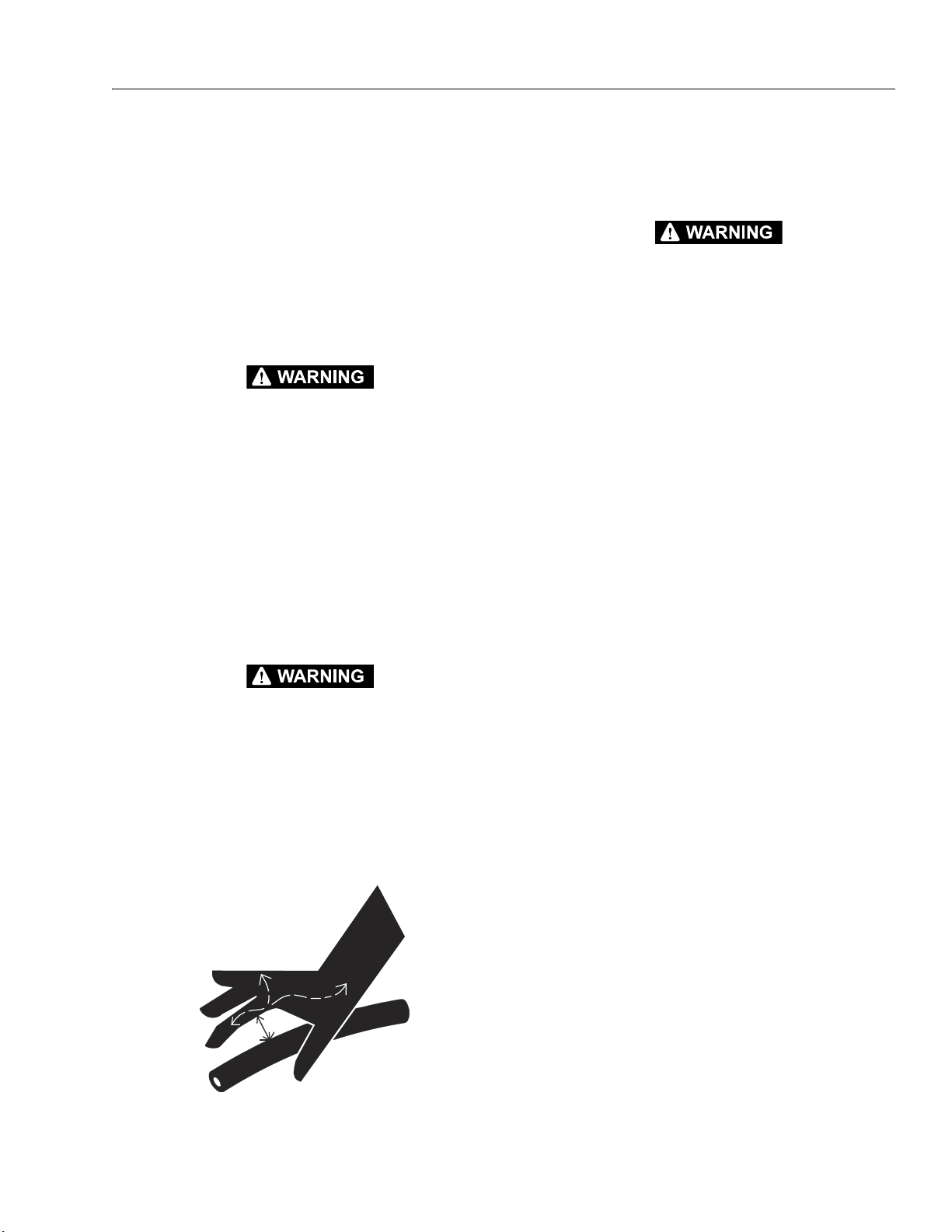
HYDRAULIC SYSTEM SAFETY
It should be noted that the machines hydraulic systems
operate at extremely high potentially dangerous pressures. Every effort should be made to relieve any system
pressure prior to disconnecting or removing any portion of the system.
MAINTENANCE
FAILURE TO COMPLY WITH SAFETY PRECAUTIONS LISTED IN THIS SECTION COULD RESULT IN MACHINE DAMAGE, PERSONNEL INJURY OR
DEATH AND IS A SAFETY VIOLATION.
• No smoking is mandatory. Never refuel during electrical storms. Ensure that fuel cap is closed and secure at
all other times.
• Remove all rings, watches and jewelry when performing any maintenance.
• Do not wear long hair unrestrained, or loose-fitting
clothing and neckties which are apt to become caught
on or entangled in equipment.
• Observe and obey all warnings and cautions on
machine and in service manual.
• Keep oil, grease, water, etc. wiped from standing surfaces and hand holds.
• Use caution when checking a hot, pressurized coolant
system.
• Never work under an elevated platform until it has
been safely restrained from any movement by blocking or overhead sling, or the safety prop has been
engaged.
• Before making adjustments, lubricating or performing
any other maintenance, shut off all power controls.
• Battery should always be disconnected during
replacement of electrical components.
• Keep all support equipment and attachments stowed
in their proper place.
• Use only approved, nonflammable cleaning solvents.
3121781 a
Page 4

INTRODUCTION
REVISION LOG
Original Issue A - September 03, 2018
b 3121781
Page 5

TABLE OF CONTENTS
TABLE OF CONTENTS
SUBJECT - SECTION, PARAGRAPH PAGE NO.
SECTION - INTRODUCTION - MAINTENANCE SAFETY PRECAUTIONS
General . . . . . . . . . . . . . . . . . . . . . . . . . . . . . . . . . . . . . . . . . . . . . . . . . . . . . . . . . . . . . . . . . . . . . . . . . . . . . . . . . . a
Hydraulic System Safety . . . . . . . . . . . . . . . . . . . . . . . . . . . . . . . . . . . . . . . . . . . . . . . . . . . . . . . . . . . . . . . . . . a
Maintenance . . . . . . . . . . . . . . . . . . . . . . . . . . . . . . . . . . . . . . . . . . . . . . . . . . . . . . . . . . . . . . . . . . . . . . . . . . . . . a
SECTION 1 - SPECIFICATIONS
1.1 Specifications . . . . . . . . . . . . . . . . . . . . . . . . . . . . . . . . . . . . . . . . . . . . . . . . . . . . . . . . . . . . . . . . . . . . . . . . . . . . 1-1
Operating Specifications . . . . . . . . . . . . . . . . . . . . . . . . . . . . . . . . . . . . . . . . . . . . . . . . . . . . . . . . . . . . 1-1
Generator Specifications (If Equipped) . . . . . . . . . . . . . . . . . . . . . . . . . . . . . . . . . . . . . . . . . . . . . . . 1-1
Dimensional Data . . . . . . . . . . . . . . . . . . . . . . . . . . . . . . . . . . . . . . . . . . . . . . . . . . . . . . . . . . . . . . . . . . . 1-2
Capacities . . . . . . . . . . . . . . . . . . . . . . . . . . . . . . . . . . . . . . . . . . . . . . . . . . . . . . . . . . . . . . . . . . . . . . . . . . 1-2
Drive Information . . . . . . . . . . . . . . . . . . . . . . . . . . . . . . . . . . . . . . . . . . . . . . . . . . . . . . . . . . . . . . . . . . . 1-2
Steering Information . . . . . . . . . . . . . . . . . . . . . . . . . . . . . . . . . . . . . . . . . . . . . . . . . . . . . . . . . . . . . . . . 1-2
Tires . . . . . . . . . . . . . . . . . . . . . . . . . . . . . . . . . . . . . . . . . . . . . . . . . . . . . . . . . . . . . . . . . . . . . . . . . . . . . . . . 1-2
Critical Stability Weights . . . . . . . . . . . . . . . . . . . . . . . . . . . . . . . . . . . . . . . . . . . . . . . . . . . . . . . . . . . . 1-2
Major Component Weights . . . . . . . . . . . . . . . . . . . . . . . . . . . . . . . . . . . . . . . . . . . . . . . . . . . . . . . . . 1-2
1.2 Serial Number Locations . . . . . . . . . . . . . . . . . . . . . . . . . . . . . . . . . . . . . . . . . . . . . . . . . . . . . . . . . . . . . . . . . . 1-3
1.3 Lubrication. . . . . . . . . . . . . . . . . . . . . . . . . . . . . . . . . . . . . . . . . . . . . . . . . . . . . . . . . . . . . . . . . . . . . . . . . . . . . . . 1-3
Hydraulic Oil Specifications. . . . . . . . . . . . . . . . . . . . . . . . . . . . . . . . . . . . . . . . . . . . . . . . . . . . . . . . . . 1-3
1.4 Hydraulic Pressure Settings . . . . . . . . . . . . . . . . . . . . . . . . . . . . . . . . . . . . . . . . . . . . . . . . . . . . . . . . . . . . . . 1-4
1.5 Hydraulic Cylinder Specifications . . . . . . . . . . . . . . . . . . . . . . . . . . . . . . . . . . . . . . . . . . . . . . . . . . . . . . . . . 1-4
1.6 Engine SPecifications . . . . . . . . . . . . . . . . . . . . . . . . . . . . . . . . . . . . . . . . . . . . . . . . . . . . . . . . . . . . . . . . . . . . . 1-5
1.7 Platform Height/Tilt Limit Settings . . . . . . . . . . . . . . . . . . . . . . . . . . . . . . . . . . . . . . . . . . . . . . . . . . . . . . . . 1-6
1.8 Torque Charts . . . . . . . . . . . . . . . . . . . . . . . . . . . . . . . . . . . . . . . . . . . . . . . . . . . . . . . . . . . . . . . . . . . . . . . . . . . . 1-9
SECTION 2 - GENERAL
2.1 Machine Preparation, Inspection, and Maintenance . . . . . . . . . . . . . . . . . . . . . . . . . . . . . . . . . . . . . . .2-1
General . . . . . . . . . . . . . . . . . . . . . . . . . . . . . . . . . . . . . . . . . . . . . . . . . . . . . . . . . . . . . . . . . . . . . . . . . . . . . 2-1
Preparation, Inspection, and Maintenance . . . . . . . . . . . . . . . . . . . . . . . . . . . . . . . . . . . . . . . . . . . 2-1
Pre-Start Inspection . . . . . . . . . . . . . . . . . . . . . . . . . . . . . . . . . . . . . . . . . . . . . . . . . . . . . . . . . . . . . . . . . 2-1
Pre-Delivery Inspection and Frequent Inspection. . . . . . . . . . . . . . . . . . . . . . . . . . . . . . . . . . . . . 2-1
Annual Machine Inspection . . . . . . . . . . . . . . . . . . . . . . . . . . . . . . . . . . . . . . . . . . . . . . . . . . . . . . . . . 2-1
Preventative Maintenance . . . . . . . . . . . . . . . . . . . . . . . . . . . . . . . . . . . . . . . . . . . . . . . . . . . . . . . . . . 2-1
2.2 Preventive Maintenance and Inspection Schedule . . . . . . . . . . . . . . . . . . . . . . . . . . . . . . . . . . . . . . . . . 2-2
Maintenance and Inspection Schedule Codes . . . . . . . . . . . . . . . . . . . . . . . . . . . . . . . . . . . . . . . . 2-2
Footnotes . . . . . . . . . . . . . . . . . . . . . . . . . . . . . . . . . . . . . . . . . . . . . . . . . . . . . . . . . . . . . . . . . . . . . . . . . . 2-4
2.3 Service and Guidelines . . . . . . . . . . . . . . . . . . . . . . . . . . . . . . . . . . . . . . . . . . . . . . . . . . . . . . . . . . . . . . . . . . . 2-5
General . . . . . . . . . . . . . . . . . . . . . . . . . . . . . . . . . . . . . . . . . . . . . . . . . . . . . . . . . . . . . . . . . . . . . . . . . . . . . 2-5
Safety and Workmanship . . . . . . . . . . . . . . . . . . . . . . . . . . . . . . . . . . . . . . . . . . . . . . . . . . . . . . . . . . . . 2-5
Cleanliness . . . . . . . . . . . . . . . . . . . . . . . . . . . . . . . . . . . . . . . . . . . . . . . . . . . . . . . . . . . . . . . . . . . . . . . . . 2-5
Components Removal and Installation. . . . . . . . . . . . . . . . . . . . . . . . . . . . . . . . . . . . . . . . . . . . . . . 2-5
Component Disassembly and Reassembly . . . . . . . . . . . . . . . . . . . . . . . . . . . . . . . . . . . . . . . . . . . 2-5
Pressure-Fit Parts . . . . . . . . . . . . . . . . . . . . . . . . . . . . . . . . . . . . . . . . . . . . . . . . . . . . . . . . . . . . . . . . . . . 2-5
Bearings . . . . . . . . . . . . . . . . . . . . . . . . . . . . . . . . . . . . . . . . . . . . . . . . . . . . . . . . . . . . . . . . . . . . . . . . . . . . 2-5
Gaskets . . . . . . . . . . . . . . . . . . . . . . . . . . . . . . . . . . . . . . . . . . . . . . . . . . . . . . . . . . . . . . . . . . . . . . . . . . . . . 2-5
Bolt Usage and Torque Application . . . . . . . . . . . . . . . . . . . . . . . . . . . . . . . . . . . . . . . . . . . . . . . . . . 2-5
Hydraulic Lines and Electrical Wiring. . . . . . . . . . . . . . . . . . . . . . . . . . . . . . . . . . . . . . . . . . . . . . . . . 2-6
Hydraulic System . . . . . . . . . . . . . . . . . . . . . . . . . . . . . . . . . . . . . . . . . . . . . . . . . . . . . . . . . . . . . . . . . . . 2-6
Lubrication . . . . . . . . . . . . . . . . . . . . . . . . . . . . . . . . . . . . . . . . . . . . . . . . . . . . . . . . . . . . . . . . . . . . . . . . . 2-6
Battery . . . . . . . . . . . . . . . . . . . . . . . . . . . . . . . . . . . . . . . . . . . . . . . . . . . . . . . . . . . . . . . . . . . . . . . . . . . . . 2-6
3121781 i
Page 6

TABLE OF CONTENTS
Lubrication and Servicing . . . . . . . . . . . . . . . . . . . . . . . . . . . . . . . . . . . . . . . . . . . . . . . . . . . . . . . . . . . . 2-6
2.4 Lubrication and Information . . . . . . . . . . . . . . . . . . . . . . . . . . . . . . . . . . . . . . . . . . . . . . . . . . . . . . . . . . . . . . 2-6
Hydraulic System . . . . . . . . . . . . . . . . . . . . . . . . . . . . . . . . . . . . . . . . . . . . . . . . . . . . . . . . . . . . . . . . . . . . 2-6
Changing Hydraulic Oil . . . . . . . . . . . . . . . . . . . . . . . . . . . . . . . . . . . . . . . . . . . . . . . . . . . . . . . . . . . . . . 2-7
Lubrication Specifications . . . . . . . . . . . . . . . . . . . . . . . . . . . . . . . . . . . . . . . . . . . . . . . . . . . . . . . . . . . . 2-7
2.5 Service Maintenance components . . . . . . . . . . . . . . . . . . . . . . . . . . . . . . . . . . . . . . . . . . . . . . . . . . . . . . . . 2-7
Setting Scissor Arm Safety Prop . . . . . . . . . . . . . . . . . . . . . . . . . . . . . . . . . . . . . . . . . . . . . . . . . . . . . . 2-7
General Maintenance Tips. . . . . . . . . . . . . . . . . . . . . . . . . . . . . . . . . . . . . . . . . . . . . . . . . . . . . . . . . . . . 2-8
Fuel Tank . . . . . . . . . . . . . . . . . . . . . . . . . . . . . . . . . . . . . . . . . . . . . . . . . . . . . . . . . . . . . . . . . . . . . . . . . . . . 2-9
Drive Hub . . . . . . . . . . . . . . . . . . . . . . . . . . . . . . . . . . . . . . . . . . . . . . . . . . . . . . . . . . . . . . . . . . . . . . . . . . . 2-9
Scissor Arms - Sliding Wear Pads . . . . . . . . . . . . . . . . . . . . . . . . . . . . . . . . . . . . . . . . . . . . . . . . . . . . . 2-9
Hydraulic Oil Tank . . . . . . . . . . . . . . . . . . . . . . . . . . . . . . . . . . . . . . . . . . . . . . . . . . . . . . . . . . . . . . . . . . . 2-9
Hydraulic Charge Filter . . . . . . . . . . . . . . . . . . . . . . . . . . . . . . . . . . . . . . . . . . . . . . . . . . . . . . . . . . . . . . . 2-9
Oil Change with Filter . . . . . . . . . . . . . . . . . . . . . . . . . . . . . . . . . . . . . . . . . . . . . . . . . . . . . . . . . . . . . . . . 2-10
Fuel/Water Separator Filter (Diesel) - Kubota . . . . . . . . . . . . . . . . . . . . . . . . . . . . . . . . . . . . . . . . . . 2-10
Fuel Strainer (Diesel) - Kubota . . . . . . . . . . . . . . . . . . . . . . . . . . . . . . . . . . . . . . . . . . . . . . . . . . . . . . . . 2-10
Fuel Filter (Gas) - Kubota . . . . . . . . . . . . . . . . . . . . . . . . . . . . . . . . . . . . . . . . . . . . . . . . . . . . . . . . . . . . . 2-11
Air Filter . . . . . . . . . . . . . . . . . . . . . . . . . . . . . . . . . . . . . . . . . . . . . . . . . . . . . . . . . . . . . . . . . . . . . . . . . . . . . 2-11
Engine Coolant . . . . . . . . . . . . . . . . . . . . . . . . . . . . . . . . . . . . . . . . . . . . . . . . . . . . . . . . . . . . . . . . . . . . . . 2-11
2.6 Cylinder Drift Test . . . . . . . . . . . . . . . . . . . . . . . . . . . . . . . . . . . . . . . . . . . . . . . . . . . . . . . . . . . . . . . . . . . . . . . . 2-12
Platform Drift . . . . . . . . . . . . . . . . . . . . . . . . . . . . . . . . . . . . . . . . . . . . . . . . . . . . . . . . . . . . . . . . . . . . . . . . 2-12
Cylinder Drift . . . . . . . . . . . . . . . . . . . . . . . . . . . . . . . . . . . . . . . . . . . . . . . . . . . . . . . . . . . . . . . . . . . . . . . . 2-12
2.7 Pins and Composite Bearing Repair Guidelines . . . . . . . . . . . . . . . . . . . . . . . . . . . . . . . . . . . . . . . . . . . . 2-12
SECTION 3 - CHASSIS, PLATFORM & SCISSOR ARMS
3.1 Operating Characteristics . . . . . . . . . . . . . . . . . . . . . . . . . . . . . . . . . . . . . . . . . . . . . . . . . . . . . . . . . . . . . . . . . 3-1
Leveling Jacks . . . . . . . . . . . . . . . . . . . . . . . . . . . . . . . . . . . . . . . . . . . . . . . . . . . . . . . . . . . . . . . . . . . . . . . 3-1
Generator . . . . . . . . . . . . . . . . . . . . . . . . . . . . . . . . . . . . . . . . . . . . . . . . . . . . . . . . . . . . . . . . . . . . . . . . . . . 3-1
Lift . . . . . . . . . . . . . . . . . . . . . . . . . . . . . . . . . . . . . . . . . . . . . . . . . . . . . . . . . . . . . . . . . . . . . . . . . . . . . . . . . . 3-1
Drive . . . . . . . . . . . . . . . . . . . . . . . . . . . . . . . . . . . . . . . . . . . . . . . . . . . . . . . . . . . . . . . . . . . . . . . . . . . . . . . . 3-1
3.2 Tires, Wheels & Drive Assembly . . . . . . . . . . . . . . . . . . . . . . . . . . . . . . . . . . . . . . . . . . . . . . . . . . . . . . . . . . . 3-1
Tire Inflation . . . . . . . . . . . . . . . . . . . . . . . . . . . . . . . . . . . . . . . . . . . . . . . . . . . . . . . . . . . . . . . . . . . . . . . . . 3-1
Tire Damage . . . . . . . . . . . . . . . . . . . . . . . . . . . . . . . . . . . . . . . . . . . . . . . . . . . . . . . . . . . . . . . . . . . . . . . . . 3-1
Tire Replacement . . . . . . . . . . . . . . . . . . . . . . . . . . . . . . . . . . . . . . . . . . . . . . . . . . . . . . . . . . . . . . . . . . . . 3-1
Wheel Replacement . . . . . . . . . . . . . . . . . . . . . . . . . . . . . . . . . . . . . . . . . . . . . . . . . . . . . . . . . . . . . . . . . 3-2
Wheel Installation. . . . . . . . . . . . . . . . . . . . . . . . . . . . . . . . . . . . . . . . . . . . . . . . . . . . . . . . . . . . . . . . . . . . 3-2
Drive Assembly . . . . . . . . . . . . . . . . . . . . . . . . . . . . . . . . . . . . . . . . . . . . . . . . . . . . . . . . . . . . . . . . . . . . . . 3-3
3.3 Drive Hub (Fairfield) . . . . . . . . . . . . . . . . . . . . . . . . . . . . . . . . . . . . . . . . . . . . . . . . . . . . . . . . . . . . . . . . . . . . . . 3-4
Roll and Leak Testing . . . . . . . . . . . . . . . . . . . . . . . . . . . . . . . . . . . . . . . . . . . . . . . . . . . . . . . . . . . . . . . . 3-4
Tightening and Torquing Bolts . . . . . . . . . . . . . . . . . . . . . . . . . . . . . . . . . . . . . . . . . . . . . . . . . . . . . . . 3-4
Oil Information . . . . . . . . . . . . . . . . . . . . . . . . . . . . . . . . . . . . . . . . . . . . . . . . . . . . . . . . . . . . . . . . . . . . . . 3-4
Main Disassembly for Drive Hub . . . . . . . . . . . . . . . . . . . . . . . . . . . . . . . . . . . . . . . . . . . . . . . . . . . . . . 3-8
Hub-Spindle Disassembly . . . . . . . . . . . . . . . . . . . . . . . . . . . . . . . . . . . . . . . . . . . . . . . . . . . . . . . . . . . . 3-8
Cover Disassembly . . . . . . . . . . . . . . . . . . . . . . . . . . . . . . . . . . . . . . . . . . . . . . . . . . . . . . . . . . . . . . . . . . . 3-9
Carrier Disassembly . . . . . . . . . . . . . . . . . . . . . . . . . . . . . . . . . . . . . . . . . . . . . . . . . . . . . . . . . . . . . . . . . . 3-9
Carrier Assembly. . . . . . . . . . . . . . . . . . . . . . . . . . . . . . . . . . . . . . . . . . . . . . . . . . . . . . . . . . . . . . . . . . . . . 3-9
Cover Sub-Assembly . . . . . . . . . . . . . . . . . . . . . . . . . . . . . . . . . . . . . . . . . . . . . . . . . . . . . . . . . . . . . . . . . 3-11
Hub-Spindle Sub-Assembly . . . . . . . . . . . . . . . . . . . . . . . . . . . . . . . . . . . . . . . . . . . . . . . . . . . . . . . . . . 3-12
Main Assembly . . . . . . . . . . . . . . . . . . . . . . . . . . . . . . . . . . . . . . . . . . . . . . . . . . . . . . . . . . . . . . . . . . . . . . 3-14
Tool List . . . . . . . . . . . . . . . . . . . . . . . . . . . . . . . . . . . . . . . . . . . . . . . . . . . . . . . . . . . . . . . . . . . . . . . . . . . . . 3-19
Re-Aligning Torque Hub Input Coupling . . . . . . . . . . . . . . . . . . . . . . . . . . . . . . . . . . . . . . . . . . . . . . 3-19
ii 3121781
Page 7

TABLE OF CONTENTS
3.4 Drive Motor (Sauer). . . . . . . . . . . . . . . . . . . . . . . . . . . . . . . . . . . . . . . . . . . . . . . . . . . . . . . . . . . . . . . . . . . . . . . 3-20
Description . . . . . . . . . . . . . . . . . . . . . . . . . . . . . . . . . . . . . . . . . . . . . . . . . . . . . . . . . . . . . . . . . . . . . . . . . 3-20
Shaft Seal Replacement . . . . . . . . . . . . . . . . . . . . . . . . . . . . . . . . . . . . . . . . . . . . . . . . . . . . . . . . . . . . . 3-20
Loop Flushing Valve . . . . . . . . . . . . . . . . . . . . . . . . . . . . . . . . . . . . . . . . . . . . . . . . . . . . . . . . . . . . . . . . 3-21
Troubleshooting . . . . . . . . . . . . . . . . . . . . . . . . . . . . . . . . . . . . . . . . . . . . . . . . . . . . . . . . . . . . . . . . . . . 3-22
Disassembly . . . . . . . . . . . . . . . . . . . . . . . . . . . . . . . . . . . . . . . . . . . . . . . . . . . . . . . . . . . . . . . . . . . . . . . . 3-23
Inspection . . . . . . . . . . . . . . . . . . . . . . . . . . . . . . . . . . . . . . . . . . . . . . . . . . . . . . . . . . . . . . . . . . . . . . . . . . 3-27
Assembly . . . . . . . . . . . . . . . . . . . . . . . . . . . . . . . . . . . . . . . . . . . . . . . . . . . . . . . . . . . . . . . . . . . . . . . . . . . 3-29
Initial Start-Up Procedures . . . . . . . . . . . . . . . . . . . . . . . . . . . . . . . . . . . . . . . . . . . . . . . . . . . . . . . . . . 3-34
3.5 Axle Installation . . . . . . . . . . . . . . . . . . . . . . . . . . . . . . . . . . . . . . . . . . . . . . . . . . . . . . . . . . . . . . . . . . . . . . . . . . 3-35
Front Axle Assembly (Fixed) . . . . . . . . . . . . . . . . . . . . . . . . . . . . . . . . . . . . . . . . . . . . . . . . . . . . . . . . . 3-35
Front Axle Assembly (Oscillating) . . . . . . . . . . . . . . . . . . . . . . . . . . . . . . . . . . . . . . . . . . . . . . . . . . . . 3-36
Steering Assembly . . . . . . . . . . . . . . . . . . . . . . . . . . . . . . . . . . . . . . . . . . . . . . . . . . . . . . . . . . . . . . . . . . 3-37
Axle Lockout Cylinder . . . . . . . . . . . . . . . . . . . . . . . . . . . . . . . . . . . . . . . . . . . . . . . . . . . . . . . . . . . . . . . 3-38
3.6 Leveling Jacks . . . . . . . . . . . . . . . . . . . . . . . . . . . . . . . . . . . . . . . . . . . . . . . . . . . . . . . . . . . . . . . . . . . . . . . . . . . . 3-39
Cylinder Removal . . . . . . . . . . . . . . . . . . . . . . . . . . . . . . . . . . . . . . . . . . . . . . . . . . . . . . . . . . . . . . . . . . . 3-39
Assembly Removal . . . . . . . . . . . . . . . . . . . . . . . . . . . . . . . . . . . . . . . . . . . . . . . . . . . . . . . . . . . . . . . . . . 3-40
3.7 Platform . . . . . . . . . . . . . . . . . . . . . . . . . . . . . . . . . . . . . . . . . . . . . . . . . . . . . . . . . . . . . . . . . . . . . . . . . . . . . . . . . 3-41
Platform Control Station . . . . . . . . . . . . . . . . . . . . . . . . . . . . . . . . . . . . . . . . . . . . . . . . . . . . . . . . . . . . 3-42
Joystick Controller . . . . . . . . . . . . . . . . . . . . . . . . . . . . . . . . . . . . . . . . . . . . . . . . . . . . . . . . . . . . . . . . . . 3-43
3.8 Scissor Arms. . . . . . . . . . . . . . . . . . . . . . . . . . . . . . . . . . . . . . . . . . . . . . . . . . . . . . . . . . . . . . . . . . . . . . . . . . . . . . 3-44
Lift Cylinder Removal . . . . . . . . . . . . . . . . . . . . . . . . . . . . . . . . . . . . . . . . . . . . . . . . . . . . . . . . . . . . . . . 3-44
Scissor Arms Removal . . . . . . . . . . . . . . . . . . . . . . . . . . . . . . . . . . . . . . . . . . . . . . . . . . . . . . . . . . . . . . . 3-44
Scissor Arm Assembly Removal . . . . . . . . . . . . . . . . . . . . . . . . . . . . . . . . . . . . . . . . . . . . . . . . . . . . . . 3-44
3.9 Side Compartment Covers . . . . . . . . . . . . . . . . . . . . . . . . . . . . . . . . . . . . . . . . . . . . . . . . . . . . . . . . . . . . . . . . 3-48
Cover Removal. . . . . . . . . . . . . . . . . . . . . . . . . . . . . . . . . . . . . . . . . . . . . . . . . . . . . . . . . . . . . . . . . . . . . . 3-50
Cover installation . . . . . . . . . . . . . . . . . . . . . . . . . . . . . . . . . . . . . . . . . . . . . . . . . . . . . . . . . . . . . . . . . . . 3-50
3.10 Ground Control Station . . . . . . . . . . . . . . . . . . . . . . . . . . . . . . . . . . . . . . . . . . . . . . . . . . . . . . . . . . . . . . . . . . . 3-50
Control Station Removal . . . . . . . . . . . . . . . . . . . . . . . . . . . . . . . . . . . . . . . . . . . . . . . . . . . . . . . . . . . . 3-50
Ground Control Station Components . . . . . . . . . . . . . . . . . . . . . . . . . . . . . . . . . . . . . . . . . . . . . . . 3-51
Options Control Module . . . . . . . . . . . . . . . . . . . . . . . . . . . . . . . . . . . . . . . . . . . . . . . . . . . . . . . . . . . . 3-52
3.11 Battery . . . . . . . . . . . . . . . . . . . . . . . . . . . . . . . . . . . . . . . . . . . . . . . . . . . . . . . . . . . . . . . . . . . . . . . . . . . . . . . . . . . 3-53
3.12 Fuel Tank . . . . . . . . . . . . . . . . . . . . . . . . . . . . . . . . . . . . . . . . . . . . . . . . . . . . . . . . . . . . . . . . . . . . . . . . . . . . . . . . 3-54
3.13 Hydraulic Tank . . . . . . . . . . . . . . . . . . . . . . . . . . . . . . . . . . . . . . . . . . . . . . . . . . . . . . . . . . . . . . . . . . . . . . . . . . . 3-55
3.14 Kubota Engine . . . . . . . . . . . . . . . . . . . . . . . . . . . . . . . . . . . . . . . . . . . . . . . . . . . . . . . . . . . . . . . . . . . . . . . . . . . 3-56
Engine Tray - Swing Out . . . . . . . . . . . . . . . . . . . . . . . . . . . . . . . . . . . . . . . . . . . . . . . . . . . . . . . . . . . . . 3-56
Dual Fuel/LPG System . . . . . . . . . . . . . . . . . . . . . . . . . . . . . . . . . . . . . . . . . . . . . . . . . . . . . . . . . . . . . . . 3-57
Changing From Gasoline to LP Gas . . . . . . . . . . . . . . . . . . . . . . . . . . . . . . . . . . . . . . . . . . . . . . . . . . 3-57
Changing From LP Gas to Gasoline . . . . . . . . . . . . . . . . . . . . . . . . . . . . . . . . . . . . . . . . . . . . . . . . . . 3-57
Using Liquid Petroleum (LP) Gas. . . . . . . . . . . . . . . . . . . . . . . . . . . . . . . . . . . . . . . . . . . . . . . . . . . . . 3-57
3.15 Propane Fuel System Pressure Relief . . . . . . . . . . . . . . . . . . . . . . . . . . . . . . . . . . . . . . . . . . . . . . . . . . . . . . 3-57
3.16 Propane Fuel System Leak Test . . . . . . . . . . . . . . . . . . . . . . . . . . . . . . . . . . . . . . . . . . . . . . . . . . . . . . . . . . . 3-57
Generator (if equipped) . . . . . . . . . . . . . . . . . . . . . . . . . . . . . . . . . . . . . . . . . . . . . . . . . . . . . . . . . . . . . 3-58
Exhaust System . . . . . . . . . . . . . . . . . . . . . . . . . . . . . . . . . . . . . . . . . . . . . . . . . . . . . . . . . . . . . . . . . . . . . 3-59
DUAL FUEL - GAS/LPG. . . . . . . . . . . . . . . . . . . . . . . . . . . . . . . . . . . . . . . . . . . . . . . . . . . . . . . . . . . . . . . 3-59
DIESEL. . . . . . . . . . . . . . . . . . . . . . . . . . . . . . . . . . . . . . . . . . . . . . . . . . . . . . . . . . . . . . . . . . . . . . . . . . . . . . 3-59
Air Cleaner System . . . . . . . . . . . . . . . . . . . . . . . . . . . . . . . . . . . . . . . . . . . . . . . . . . . . . . . . . . . . . . . . . . 3-60
Radiator . . . . . . . . . . . . . . . . . . . . . . . . . . . . . . . . . . . . . . . . . . . . . . . . . . . . . . . . . . . . . . . . . . . . . . . . . . . . 3-61
Engine Electrical Component Locations. . . . . . . . . . . . . . . . . . . . . . . . . . . . . . . . . . . . . . . . . . . . . . 3-62
Hydraulic Pump Installation . . . . . . . . . . . . . . . . . . . . . . . . . . . . . . . . . . . . . . . . . . . . . . . . . . . . . . . . . 3-64
Pump Coupling Assembly . . . . . . . . . . . . . . . . . . . . . . . . . . . . . . . . . . . . . . . . . . . . . . . . . . . . .
Engine Removal . . . . . . . . . . . . . . . . . . . . . . . . . . . . . . . . . . . . . . . . . . . . . . . . . . . . . . . . . . . . . . . . . . . . 3-66
. . . . . . 3-65
3121781 iii
Page 8

TABLE OF CONTENTS
SECTION 4 - BASIC HYDRAULIC INFORMATION & SCHEMATICS
4.1 Cylinders - Theory of Operation . . . . . . . . . . . . . . . . . . . . . . . . . . . . . . . . . . . . . . . . . . . . . . . . . . . . . . . . . . . 4-1
4.2 Valves - Theory of Operation . . . . . . . . . . . . . . . . . . . . . . . . . . . . . . . . . . . . . . . . . . . . . . . . . . . . . . . . . . . . . . 4-1
Solenoid Control Valves (Bang-Bang) . . . . . . . . . . . . . . . . . . . . . . . . . . . . . . . . . . . . . . . . . . . . . . . . . 4-1
Relief Valves . . . . . . . . . . . . . . . . . . . . . . . . . . . . . . . . . . . . . . . . . . . . . . . . . . . . . . . . . . . . . . . . . . . . . . . . . 4-1
Crossover Relief Valves . . . . . . . . . . . . . . . . . . . . . . . . . . . . . . . . . . . . . . . . . . . . . . . . . . . . . . . . . . . . . . . 4-1
4.3 Cylinder Checking Procedure . . . . . . . . . . . . . . . . . . . . . . . . . . . . . . . . . . . . . . . . . . . . . . . . . . . . . . . . . . . . . 4-1
Cylinders Without Counterbalance Valves . . . . . . . . . . . . . . . . . . . . . . . . . . . . . . . . . . . . . . . . . . . . 4-1
Cylinders With Single Counterbalance Valve . . . . . . . . . . . . . . . . . . . . . . . . . . . . . . . . . . . . . . . . . . 4-2
4.4 Oscillating AXLE - Lockout Cylinder Test (if equipped) . . . . . . . . . . . . . . . . . . . . . . . . . . . . . . . . . . . . . 4-2
Left Side Wheel Test . . . . . . . . . . . . . . . . . . . . . . . . . . . . . . . . . . . . . . . . . . . . . . . . . . . . . . . . . . . . . . . . . 4-2
Right Side Wheel Test . . . . . . . . . . . . . . . . . . . . . . . . . . . . . . . . . . . . . . . . . . . . . . . . . . . . . . . . . . . . . . . . 4-3
4.5 Drive Pump Pre-fill Procedure. . . . . . . . . . . . . . . . . . . . . . . . . . . . . . . . . . . . . . . . . . . . . . . . . . . . . . . . . . . . . 4-3
Pre-Fill of the Drive Pump Housing Without HOC . . . . . . . . . . . . . . . . . . . . . . . . . . . . . . . . . . . . . 4-3
Pre-Fill of the Drive Pump Housing With HOC . . . . . . . . . . . . . . . . . . . . . . . . . . . . . . . . . . . . . . . . . 4-3
Priming the Gear Pump . . . . . . . . . . . . . . . . . . . . . . . . . . . . . . . . . . . . . . . . . . . . . . . . . . . . . . . . . . . . . . 4-3
4.6 Drive Pump Start-up Procedure . . . . . . . . . . . . . . . . . . . . . . . . . . . . . . . . . . . . . . . . . . . . . . . . . . . . . . . . . . . 4-4
4.7 Hydraulic Component Start-Up Procedures & Recommendations . . . . . . . . . . . . . . . . . . . . . . . . . . 4-5
4.8 Hydraulic Connection Assembly and Torque Specification . . . . . . . . . . . . . . . . . . . . . . . . . . . . . . . . . 4-7
Tapered Thread Types . . . . . . . . . . . . . . . . . . . . . . . . . . . . . . . . . . . . . . . . . . . . . . . . . . . . . . . . . . . . . . . 4-7
Straight Thread Types, Tube and Hose Connections . . . . . . . . . . . . . . . . . . . . . . . . . . . . . . . . . . . 4-7
Straight Thread Types, Port Connections. . . . . . . . . . . . . . . . . . . . . . . . . . . . . . . . . . . . . . . . . . . . . . 4-8
Flange Connection Types . . . . . . . . . . . . . . . . . . . . . . . . . . . . . . . . . . . . . . . . . . . . . . . . . . . . . . . . . . . . 4-8
Tightening Methods . . . . . . . . . . . . . . . . . . . . . . . . . . . . . . . . . . . . . . . . . . . . . . . . . . . . . . . . . . . . . . . . . 4-8
Assembly And Torque Specifications . . . . . . . . . . . . . . . . . . . . . . . . . . . . . . . . . . . . . . . . . . . . . . . . . 4-9
Assembly Instructions for American Standard Pipe Thread Tapered (NPTF)
Connections. . . . . . . . . . . . . . . . . . . . . . . . . . . . . . . . . . . . . . . . . . . . . . . . . . . . . . . . . . . . . . . . . . . . . . . . . 4-10
Assembly Instructions for British Standard Pipe Thread Tapered (BSPT) Connections . . . 4-11
Assembly Instructions for 37° (JIC) Flare Fittings. . . . . . . . . . . . . . . . . . . . . . . . . . . . . . . . . . . . . . . 4-12
Assembly Instructions for 45° SAE Flare Fittings . . . . . . . . . . . . . . . . . . . . . . . . . . . . . . . . . . . . . . . 4-15
Assembly Instructions for O-ring Face Seal (ORFS) Fittings. . . . . . . . . . . . . . . . . . . . . . . . . . . . . 4-17
Assembly Instructions for DIN 24° Flare Bite Type Fittings (MBTL and MBTS). . . . . . . . . . . . 4-19
Assembly Instructions for Bulkhead (BH) Fittings . . . . . . . . . . . . . . . . . . . . . . . . . . . . . . . . . . . . . . 4-21
Assembly Instructions for O-ring Boss (ORB) Fittings . . . . . . . . . . . . . . . . . . . . . . . . . . . . . . . . . . 4-24
Assembly Instructions for Adjustable Port End Metric (MFF) Fittings . . . . . . . . . . . . . . . . . . . 4-31
Assembly Instructions for Metric ISO 6149 (MPP) Port Assembly Stud Ends . . . . . . . . . . . . . 4-38
Assembly instructions for Adjustable Port End (BSPP) Fittings . . . . . . . . . . . . . . . . . . . . . . . . . 4-40
Assembly Instructions for Flange Connections: (FL61 and FL62) . . . . . . . . . . . . . . . . . . . . . . . 4-47
Double Wrench Method . . . . . . . . . . . . . . . . . . . . . . . . . . . . . . . . . . . . . . . . . . . . . . . . . . . . . . . . . . . . . 4-50
FFWR and TFFT Methods . . . . . . . . . . . . . . . . . . . . . . . . . . . . . . . . . . . . . . . . . . . . . . . . . . . . . . . . . . . . . 4-51
Adjustable Stud End Assembly . . . . . . . . . . . . . . . . . . . . . . . . . . . . . . . . . . . . . . . . . . . . . . . . . . . . . . . 4-51
O-ring Installation (Replacement). . . . . . . . . . . . . . . . . . . . . . . . . . . . . . . . . . . . . . . . . . . . . . . . . . . . . 4-52
4.9 Hydraulic Valves. . . . . . . . . . . . . . . . . . . . . . . . . . . . . . . . . . . . . . . . . . . . . . . . . . . . . . . . . . . . . . . . . . . . . . . . . . 4-53
Main Hydraulic Valve. . . . . . . . . . . . . . . . . . . . . . . . . . . . . . . . . . . . . . . . . . . . . . . . . . . . . . . . . . . . . . . . . 4-54
Flow Divider Valve . . . . . . . . . . . . . . . . . . . . . . . . . . . . . . . . . . . . . . . . . . . . . . . . . . . . . . . . . . . . . . . . . . . 4-56
Leveling Jack Directional Valve . . . . . . . . . . . . . . . . . . . . . . . . . . . . . . . . . . . . . . . . . . . . . . . . . . . . . . . 4-57
Leveling Jack Valves . . . . . . . . . . . . . . . . . . . . . . . . . . . . . . . . . . . . . . . . . . . . . . . . . . . . . . . . . . . . . . . . . 4-58
Pressure Relief Valve - Setting Procedures . . . . . . . . . . . . . . . . . . . . . . . . . . . . . . . . . . . . . . . . . . . . 4-59
4.10 Gear Pump . . . . . . . . . . . . . . . . . . . . . . . . . . . . . . . . . . . . . . . . . . . . . . . . . . . . . . . . . . . . . . . . . . . . . . . . . . . . . . . 4-60
Gear Pump Priming . . . . . . . . . . . . . . . . . . . . . . . . . . . . . . . . . . . . . . . . . . . . . . . . . . . . . . . . . . . . . . . . . . 4-61
iv 3121781
Page 9

4.11 Axial HI 45 Pump . . . . . . . . . . . . . . . . . . . . . . . . . . . . . . . . . . . . . . . . . . . . . . . . . . . . . . . . . . . . . . . . . . . . . . . . . 4-62
General Repair Instructions . . . . . . . . . . . . . . . . . . . . . . . . . . . . . . . . . . . . . . . . . . . . . . . . . . . . . . . . . . 4-64
Start-Up Procedure . . . . . . . . . . . . . . . . . . . . . . . . . . . . . . . . . . . . . . . . . . . . . . . . . . . . . . . . . . . . . . . . . 4-64
Removing the pump . . . . . . . . . . . . . . . . . . . . . . . . . . . . . . . . . . . . . . . . . . . . . . . . . . . . . . . . . . . . . . . . 4-65
Electric Control Module . . . . . . . . . . . . . . . . . . . . . . . . . . . . . . . . . . . . . . . . . . . . . . . . . . . . . . . . . . . . . 4-66
Control Solenoids . . . . . . . . . . . . . . . . . . . . . . . . . . . . . . . . . . . . . . . . . . . . . . . . . . . . . . . . . . . . . . . . . . . 4-66
Shaft Seal, Roller Bearing & Shaft Replacement. . . . . . . . . . . . . . . . . . . . . . . . . . . . . . . . . . . . . . . 4-67
Charge Pump . . . . . . . . . . . . . . . . . . . . . . . . . . . . . . . . . . . . . . . . . . . . . . . . . . . . . . . . . . . . . . . . . . . . . . . 4-67
Charge Check/HPRV . . . . . . . . . . . . . . . . . . . . . . . . . . . . . . . . . . . . . . . . . . . . . . . . . . . . . . . . . . . . . . . . 4-69
Charge Pressure Relief Valve. . . . . . . . . . . . . . . . . . . . . . . . . . . . . . . . . . . . . . . . . . . . . . . . . . . . . . . . . 4-69
Pressure Limiter Valve Replacement . . . . . . . . . . . . . . . . . . . . . . . . . . . . . . . . . . . . . . . . . . . . . . . . . 4-70
4.12 Charge Pump Filter . . . . . . . . . . . . . . . . . . . . . . . . . . . . . . . . . . . . . . . . . . . . . . . . . . . . . . . . . . . . . . . . . . . . . . . 4-70
4.13 Cylinder Repair . . . . . . . . . . . . . . . . . . . . . . . . . . . . . . . . . . . . . . . . . . . . . . . . . . . . . . . . . . . . . . . . . . . . . . . . . . . 4-71
Disassembly . . . . . . . . . . . . . . . . . . . . . . . . . . . . . . . . . . . . . . . . . . . . . . . . . . . . . . . . . . . . . . . . . . . . . . . . 4-71
Cleaning and Inspection . . . . . . . . . . . . . . . . . . . . . . . . . . . . . . . . . . . . . . . . . . . . . . . . . . . . . . . . . . . . 4-72
Assembly . . . . . . . . . . . . . . . . . . . . . . . . . . . . . . . . . . . . . . . . . . . . . . . . . . . . . . . . . . . . . . . . . . . . . . . . . . . 4-73
4.14 Cylinder Assemblies . . . . . . . . . . . . . . . . . . . . . . . . . . . . . . . . . . . . . . . . . . . . . . . . . . . . . . . . . . . . . . . . . . . . . . 4-77
Oscillating Axle Cylinder Bleeding Procedure . . . . . . . . . . . . . . . . . . . . . . . . . . . . . . . . . . . . . . . . 4-84
4.15 Hydraulic Schematics . . . . . . . . . . . . . . . . . . . . . . . . . . . . . . . . . . . . . . . . . . . . . . . . . . . . . . . . . . . . . . . . . . . . . 4-85
SECTION 5 - JLG CONTROL SYSTEM
TABLE OF CONTENTS
5.1 Hand Held Analyzer . . . . . . . . . . . . . . . . . . . . . . . . . . . . . . . . . . . . . . . . . . . . . . . . . . . . . . . . . . . . . . . . . . . . . . 5-1
To Connect the Hand Held Analyzer . . . . . . . . . . . . . . . . . . . . . . . . . . . . . . . . . . . . . . . . . . . . . . . . . 5-1
Using the Analyzer . . . . . . . . . . . . . . . . . . . . . . . . . . . . . . . . . . . . . . . . . . . . . . . . . . . . . . . . . . . . . . . . . . 5-2
Changing the Access Level of the Hand Held Analyzer. . . . . . . . . . . . . . . . . . . . . . . . . . . . . . . . 5-3
Adjusting Parameters Using the Hand Held Analyzer . . . . . . . . . . . . . . . . . . . . . . . . . . . . . . . . . 5-4
Machine Setup. . . . . . . . . . . . . . . . . . . . . . . . . . . . . . . . . . . . . . . . . . . . . . . . . . . . . . . . . . . . . . . . . . . . . . 5-4
Analyzer Menu Flow Charts . . . . . . . . . . . . . . . . . . . . . . . . . . . . . . . . . . . . . . . . . . . . . . . . . . . . . . . . . 5-6
5.2 Diagnostic Troubleshooting codes (DTC’s) and Flash Codes Description . . . . . . . . . . . . . . . . . . . . 5-9
5.3 Chassis Tilt Sensor Installation . . . . . . . . . . . . . . . . . . . . . . . . . . . . . . . . . . . . . . . . . . . . . . . . . . . . . . . . . . . . 5-18
5.4 Location Of Additional Sensors . . . . . . . . . . . . . . . . . . . . . . . . . . . . . . . . . . . . . . . . . . . . . . . . . . . . . . . . . . . 5-19
5.5 Calibration Procedures . . . . . . . . . . . . . . . . . . . . . . . . . . . . . . . . . . . . . . . . . . . . . . . . . . . . . . . . . . . . . . . . . . . 5-20
Chassis Tilt Sensor Calibration . . . . . . . . . . . . . . . . . . . . . . . . . . . . . . . . . . . . . . . . . . . . . . . . . . . . . . . 5-20
Oscillating Axle Tilt Sensor . . . . . . . . . . . . . . . . . . . . . . . . . . . . . . . . . . . . . . . . . . . . . . . . . . . . . . . . . . 5-21
Set Stow Elevation . . . . . . . . . . . . . . . . . . . . . . . . . . . . . . . . . . . . . . . . . . . . . . . . . . . . . . . . . . . . . . . . . . 5-21
5.6 Service Mode Procedures . . . . . . . . . . . . . . . . . . . . . . . . . . . . . . . . . . . . . . . . . . . . . . . . . . . . . . . . . . . . . . . . . 5-21
ECM Override (Dual Fuel Only). . . . . . . . . . . . . . . . . . . . . . . . . . . . . . . . . . . . . . . . . . . . . . . . . . . . . . . 5-21
Elevation Service. . . . . . . . . . . . . . . . . . . . . . . . . . . . . . . . . . . . . . . . . . . . . . . . . . . . . . . . . . . . . . . . . . . . 5-21
EEPROM Reset . . . . . . . . . . . . . . . . . . . . . . . . . . . . . . . . . . . . . . . . . . . . . . . . . . . . . . . . . . . . . . . . . . . . . . 5-22
Allow Drive . . . . . . . . . . . . . . . . . . . . . . . . . . . . . . . . . . . . . . . . . . . . . . . . . . . . . . . . . . . . . . . . . . . . . . . . . 5-22
Allow Leveling Jack Retract . . . . . . . . . . . . . . . . . . . . . . . . . . . . . . . . . . . . . . . . . . . . . . . . . . . . . . . . . . 5-22
5.7 Machine Configuration and Programming Settings . . . . . . . . . . . . . . . . . . . . . . . . . . . . . . . . . . . . . . . .5-23
SECTION 6 - LSS SETUP/CALIBRATION/SERVICE
6.1 Connecting the JLG Control System Analyzer. . . . . . . . . . . . . . . . . . . . . . . . . . . . . . . . . . . . . . . . . . . . . . 6-1
6.2 Help Menu & Fault Codes . . . . . . . . . . . . . . . . . . . . . . . . . . . . . . . . . . . . . . . . . . . . . . . . . . . . . . . . . . . . . . . . . 6-1
6.3 Diagnostic Menu . . . . . . . . . . . . . . . . . . . . . . . . . . . . . . . . . . . . . . . . . . . . . . . . . . . . . . . . . . . . . . . . . . . . . . . . . 6-2
6.4 Personalities . . . . . . . . . . . . . . . . . . . . . . . . . . . . . . . . . . . . . . . . . . . . . . . . . . . . . . . . . . . . . . . . . . . . . . . . . . . . . 6-2
6.5 Machine Setup Menu . . . . . . . . . . . . . . . . . . . . . . . . . . . . . . . . . . . . . . . . . . . . . . . . . . . . . . . . . . . . . . . . . . . . . 6-3
6.6 Calibration Menu . . . . . . . . . . . . . . . . . . . . . . . . . . . . . . . . . . . . . . . . . . . . . . . . . . . . . . . . . . . . . . . . . . . . . . . . . 6-3
6.7 Service . . . . . . . . . . . . . . . . . . . . . . . . . . . . . . . . . . . . . . . . . . . . . . . . . . . . . . . . . . . . . . . . . . . . . . . . . . . . . . . . . . . 6-5
Description . . . . . . . . . . . . . . . . . . . . . . . . . . . . . . . . . . . . . . . . . . . . . . . . . . . . . . . . . . . . . . . . . . . . . . . . . 6-5
3121781 v
Page 10

TABLE OF CONTENTS
6.8 Calibration . . . . . . . . . . . . . . . . . . . . . . . . . . . . . . . . . . . . . . . . . . . . . . . . . . . . . . . . . . . . . . . . . . . . . . . . . . . . . . . 6-6
Procedure . . . . . . . . . . . . . . . . . . . . . . . . . . . . . . . . . . . . . . . . . . . . . . . . . . . . . . . . . . . . . . . . . . . . . . . . . . . 6-6
Testing & Evaluation . . . . . . . . . . . . . . . . . . . . . . . . . . . . . . . . . . . . . . . . . . . . . . . . . . . . . . . . . . . . . . . . . 6-6
6.9 Troubleshooting . . . . . . . . . . . . . . . . . . . . . . . . . . . . . . . . . . . . . . . . . . . . . . . . . . . . . . . . . . . . . . . . . . . . . . . . . 6-8
SECTION 7 - GENERAL ELECTRICAL INFORMATION & SCHEMATICS
7.1 General . . . . . . . . . . . . . . . . . . . . . . . . . . . . . . . . . . . . . . . . . . . . . . . . . . . . . . . . . . . . . . . . . . . . . . . . . . . . . . . . . . 6-1
7.2 Multimeter Basics . . . . . . . . . . . . . . . . . . . . . . . . . . . . . . . . . . . . . . . . . . . . . . . . . . . . . . . . . . . . . . . . . . . . . . . . 6-1
Grounding. . . . . . . . . . . . . . . . . . . . . . . . . . . . . . . . . . . . . . . . . . . . . . . . . . . . . . . . . . . . . . . . . . . . . . . . . . . 6-1
Backprobing . . . . . . . . . . . . . . . . . . . . . . . . . . . . . . . . . . . . . . . . . . . . . . . . . . . . . . . . . . . . . . . . . . . . . . . . . 6-1
Min/Max. . . . . . . . . . . . . . . . . . . . . . . . . . . . . . . . . . . . . . . . . . . . . . . . . . . . . . . . . . . . . . . . . . . . . . . . . . . . . 6-1
Polarity . . . . . . . . . . . . . . . . . . . . . . . . . . . . . . . . . . . . . . . . . . . . . . . . . . . . . . . . . . . . . . . . . . . . . . . . . . . . . . 6-1
Scale . . . . . . . . . . . . . . . . . . . . . . . . . . . . . . . . . . . . . . . . . . . . . . . . . . . . . . . . . . . . . . . . . . . . . . . . . . . . . . . . 6-1
Voltage Measurement . . . . . . . . . . . . . . . . . . . . . . . . . . . . . . . . . . . . . . . . . . . . . . . . . . . . . . . . . . . . . . . 6-2
Resistance Measurement . . . . . . . . . . . . . . . . . . . . . . . . . . . . . . . . . . . . . . . . . . . . . . . . . . . . . . . . . . . . . 6-2
Continuity Measurement. . . . . . . . . . . . . . . . . . . . . . . . . . . . . . . . . . . . . . . . . . . . . . . . . . . . . . . . . . . . . 6-3
Current Measurement. . . . . . . . . . . . . . . . . . . . . . . . . . . . . . . . . . . . . . . . . . . . . . . . . . . . . . . . . . . . . . . . 6-3
Continuity Measurement Over Long Distances. . . . . . . . . . . . . . . . . . . . . . . . . . . . . . . . . . . . . . . . 6-4
Requirements . . . . . . . . . . . . . . . . . . . . . . . . . . . . . . . . . . . . . . . . . . . . . . . . . . . . . . . . . . . . . . . . . . . . . . . 6-4
Procedure . . . . . . . . . . . . . . . . . . . . . . . . . . . . . . . . . . . . . . . . . . . . . . . . . . . . . . . . . . . . . . . . . . . . . . . . . . . 6-4
7.3 Applying Silicone Dielectric Compound to Electrical Connections . . . . . . . . . . . . . . . . . . . . . . . . . . 6-5
Installation of Dielectric Grease . . . . . . . . . . . . . . . . . . . . . . . . . . . . . . . . . . . . . . . . . . . . . . . . . . . . . . . 6-5
Deutsch HD, DT, DTM, DRC Series . . . . . . . . . . . . . . . . . . . . . . . . . . . . . . . . . . . . . . . . . . . . . . . . . . . . 6-6
AMP Seal . . . . . . . . . . . . . . . . . . . . . . . . . . . . . . . . . . . . . . . . . . . . . . . . . . . . . . . . . . . . . . . . . . . . . . . . . . . . 6-6
AMP Mate-N-Lok. . . . . . . . . . . . . . . . . . . . . . . . . . . . . . . . . . . . . . . . . . . . . . . . . . . . . . . . . . . . . . . . . . . . . 6-6
DIN Connectors . . . . . . . . . . . . . . . . . . . . . . . . . . . . . . . . . . . . . . . . . . . . . . . . . . . . . . . . . . . . . . . . . . . . . . 6-7
Exclusions . . . . . . . . . . . . . . . . . . . . . . . . . . . . . . . . . . . . . . . . . . . . . . . . . . . . . . . . . . . . . . . . . . . . . . . . . . . 6-7
Brad Harrison / Phoenix Contact M12 . . . . . . . . . . . . . . . . . . . . . . . . . . . . . . . . . . . . . . . . . . . . . . . . . 6-7
Engine Control unit connectors . . . . . . . . . . . . . . . . . . . . . . . . . . . . . . . . . . . . . . . . . . . . . . . . . . . . . . 6-8
Sealed Enclosures. . . . . . . . . . . . . . . . . . . . . . . . . . . . . . . . . . . . . . . . . . . . . . . . . . . . . . . . . . . . . . . . . . . . 6-8
MIL-C-5015 SPEC Connector’s . . . . . . . . . . . . . . . . . . . . . . . . . . . . . . . . . . . . . . . . . . . . . . . . . . . . . . . . 6-8
Molex CMC Series Connectors . . . . . . . . . . . . . . . . . . . . . . . . . . . . . . . . . . . . . . . . . . . . . . . . . . . . . . . . 6-8
7.4 Applying Silicone Dielectric Compound To Amp Connectors. . . . . . . . . . . . . . . . . . . . . . . . . . . . . . . 6-9
Assembly . . . . . . . . . . . . . . . . . . . . . . . . . . . . . . . . . . . . . . . . . . . . . . . . . . . . . . . . . . . . . . . . . . . . . . . . . . . . 6-10
Disassembly . . . . . . . . . . . . . . . . . . . . . . . . . . . . . . . . . . . . . . . . . . . . . . . . . . . . . . . . . . . . . . . . . . . . . . . . . 6-11
Wedge Lock . . . . . . . . . . . . . . . . . . . . . . . . . . . . . . . . . . . . . . . . . . . . . . . . . . . . . . . . . . . . . . . . . . . . . . . . . 6-11
Service - Voltage Reading . . . . . . . . . . . . . . . . . . . . . . . . . . . . . . . . . . . . . . . . . . . . . . . . . . . . . . . . . . . . 6-12
7.5 Working With Deutsch Connectors. . . . . . . . . . . . . . . . . . . . . . . . . . . . . . . . . . . . . . . . . . . . . . . . . . . . . . . . 6-13
DT/DTP Series Assembly . . . . . . . . . . . . . . . . . . . . . . . . . . . . . . . . . . . . . . . . . . . . . . . . . . . . . . . . . . . . . 6-13
DT/DTP Series Disassembly. . . . . . . . . . . . . . . . . . . . . . . . . . . . . . . . . . . . . . . . . . . . . . . . . . . . . . . . . . . 6-13
HD30/HDP20 Series Assembly . . . . . . . . . . . . . . . . . . . . . . . . . . . . . . . . . . . . . . . . . . . . . . . . . . . . . . . . 6-14
HD30/HDP20 Series Disassembly . . . . . . . . . . . . . . . . . . . . . . . . . . . . . . . . . . . . . . . . . . . . . . . . . . . . . 6-14
7.6 Switches . . . . . . . . . . . . . . . . . . . . . . . . . . . . . . . . . . . . . . . . . . . . . . . . . . . . . . . . . . . . . . . . . . . . . . . . . . . . . . . . . 6-15
Basic check . . . . . . . . . . . . . . . . . . . . . . . . . . . . . . . . . . . . . . . . . . . . . . . . . . . . . . . . . . . . . . . . . . . . . . . . . . 6-15
Leveling Jacks Limit Switch. . . . . . . . . . . . . . . . . . . . . . . . . . . . . . . . . . . . . . . . . . . . . . . . . . . . . . . . . . . 6-15
Automatic Switches. . . . . . . . . . . . . . . . . . . . . . . . . . . . . . . . . . . . . . . . . . . . . . . . . . . . . . . . . . . . . . . . . . 6-16
Switch Wiring - Low Side, High Side . . . . . . . . . . . . . . . . . . . . . . . . . . . . . . . . . . . . . . . . . . . . . . . . . . 6-16
7.7 Electrical Schematics . . . . . . . . . . . . . . . . . . . . . . . . . . . . . . . . . . . . . . . . . . . . . . . . . . . . . . . . . . . . . . . . . . . . . 6-17
vi 3121781
Page 11

TABLE OF CONTENTS
LIST OF FIGURES
FIGURE NO. TITLE PAGE NO.
1-1. Serial Number Location . . . . . . . . . . . . . . . . . . . . . . . . . . . . . . . . . . . . . . . . . . . . . . . . . . . . . . . . . . . . . . . . . . .1-3
1-2. Hydraulic Oil Operating Temperature Specifications . . . . . . . . . . . . . . . . . . . . . . . . . . . . . . . . . . . . . . .1-7
1-3. Engine Oil Operating Temperature Specifications - Kubota (Dual Fuel Engine) . . . . . . . . . . . . . .1-7
1-4. Engine Oil Operating Temperature Specifications - Kubota (Diesel Engine) . . . . . . . . . . . . . . . . .1-8
1-5. Torque Chart - Sheet 1 of 5 - (SAE Fasteners) . . . . . . . . . . . . . . . . . . . . . . . . . . . . . . . . . . . . . . . . . . . . . . .1-9
1-6. Torque Chart - Sheet 2 of 5 - (SAE Fasteners) . . . . . . . . . . . . . . . . . . . . . . . . . . . . . . . . . . . . . . . . . . . . . . .1-10
1-7. Torque Chart - Sheet 3 of 5 - (SAE Fasteners) . . . . . . . . . . . . . . . . . . . . . . . . . . . . . . . . . . . . . . . . . . . . . . .1-11
1-8. Torque Chart - Sheet 4 of 5 - (METRIC Fasteners) . . . . . . . . . . . . . . . . . . . . . . . . . . . . . . . . . . . . . . . . . . . 1-12
1-9. Torque Chart - Sheet 5 of 5 - (METRIC Fasteners) . . . . . . . . . . . . . . . . . . . . . . . . . . . . . . . . . . . . . . . . . . . 1-13
2-1. Scissor Arm - Safety Prop Assembly. . . . . . . . . . . . . . . . . . . . . . . . . . . . . . . . . . . . . . . . . . . . . . . . . . . . . . . .2-7
2-2. Safety Prop Actuator Rod . . . . . . . . . . . . . . . . . . . . . . . . . . . . . . . . . . . . . . . . . . . . . . . . . . . . . . . . . . . . . . . . .2-8
2-3. Service Maintenance Components . . . . . . . . . . . . . . . . . . . . . . . . . . . . . . . . . . . . . . . . . . . . . . . . . . . . . . . .2-8
2-4. Kubota Dual Fuel (WG972-GL-E4). . . . . . . . . . . . . . . . . . . . . . . . . . . . . . . . . . . . . . . . . . . . . . . . . . . . . . . . . .2-10
2-5. Kubota Diesel (D1305-E3B - Stage IIIA and D1305-E4B - T4F). . . . . . . . . . . . . . . . . . . . . . . . . . . . . . . .2-10
3-1. Drive Assembly (Fairfield/Sauer). . . . . . . . . . . . . . . . . . . . . . . . . . . . . . . . . . . . . . . . . . . . . . . . . . . . . . . . . . .3-3
3-2. Drive Hub (Cross-Section) . . . . . . . . . . . . . . . . . . . . . . . . . . . . . . . . . . . . . . . . . . . . . . . . . . . . . . . . . . . . . . . . .3-5
3-3. Drive Hub . . . . . . . . . . . . . . . . . . . . . . . . . . . . . . . . . . . . . . . . . . . . . . . . . . . . . . . . . . . . . . . . . . . . . . . . . . . . . . . .3-6
3-4. Cluster Gear Punch Marks . . . . . . . . . . . . . . . . . . . . . . . . . . . . . . . . . . . . . . . . . . . . . . . . . . . . . . . . . . . . . . . . .3-16
3-5. Drive Motor Cross Section. . . . . . . . . . . . . . . . . . . . . . . . . . . . . . . . . . . . . . . . . . . . . . . . . . . . . . . . . . . . . . . . .3-20
3-6. Removing the Shaft Seal . . . . . . . . . . . . . . . . . . . . . . . . . . . . . . . . . . . . . . . . . . . . . . . . . . . . . . . . . . . . . . . . . .3-20
3-7. Loop Flushing Spool . . . . . . . . . . . . . . . . . . . . . . . . . . . . . . . . . . . . . . . . . . . . . . . . . . . . . . . . . . . . . . . . . . . . . .3-21
3-8. Loop Flushing Spool . . . . . . . . . . . . . . . . . . . . . . . . . . . . . . . . . . . . . . . . . . . . . . . . . . . . . . . . . . . . . . . . . . . . . .3-23
3-9. Plugs, Fittings, and Speed Sensor. . . . . . . . . . . . . . . . . . . . . . . . . . . . . . . . . . . . . . . . . . . . . . . . . . . . . . . . . .3-23
3-10. End Cap . . . . . . . . . . . . . . . . . . . . . . . . . . . . . . . . . . . . . . . . . . . . . . . . . . . . . . . . . . . . . . . . . . . . . . . . . . . . . . . . . .3-24
3-11. Valve Plate & Rear Shaft Bearing. . . . . . . . . . . . . . . . . . . . . . . . . . . . . . . . . . . . . . . . . . . . . . . . . . . . . . . . . . .3-24
3-12. Cylinder Kit . . . . . . . . . . . . . . . . . . . . . . . . . . . . . . . . . . . . . . . . . . . . . . . . . . . . . . . . . . . . . . . . . . . . . . . . . . . . . . .3-25
3-13. Shaft Seal. . . . . . . . . . . . . . . . . . . . . . . . . . . . . . . . . . . . . . . . . . . . . . . . . . . . . . . . . . . . . . . . . . . . . . . . . . . . . . . . .3-25
3-14. Shaft & Front Bearing . . . . . . . . . . . . . . . . . . . . . . . . . . . . . . . . . . . . . . . . . . . . . . . . . . . . . . . . . . . . . . . . . . . . .3-25
3-15. Swash Plate & Servo Piston . . . . . . . . . . . . . . . . . . . . . . . . . . . . . . . . . . . . . . . . . . . . . . . . . . . . . . . . . . . . . . . .3-26
3-16. Cylinder Kit Disassembly . . . . . . . . . . . . . . . . . . . . . . . . . . . . . . . . . . . . . . . . . . . . . . . . . . . . . . . . . . . . . . . . . .3-26
3-17. Servo Piston . . . . . . . . . . . . . . . . . . . . . . . . . . . . . . . . . . . . . . . . . . . . . . . . . . . . . . . . . . . . . . . . . . . . . . . . . . . . . .3-29
3-18. Cylinder Kit Assembly . . . . . . . . . . . . . . . . . . . . . . . . . . . . . . . . . . . . . . . . . . . . . . . . . . . . . . . . . . . . . . . . . . . . .3-30
3-19. Swash Plate and Journal Bearing . . . . . . . . . . . . . . . . . . . . . . . . . . . . . . . . . . . . . . . . . . . . . . . . . . . . . . . . . .3-30
3-20. Shaft and Front Bearing . . . . . . . . . . . . . . . . . . . . . . . . . . . . . . . . . . . . . . . . . . . . . . . . . . . . . . . . . . . . . . . . . . .3-31
3-21. Cylinder Kit Installation . . . . . . . . . . . . . . . . . . . . . . . . . . . . . . . . . . . . . . . . . . . . . . . . . . . . . . . . . . . . . . . . . . .3-31
3-22. Servo Spring and Minimum Angle Stop. . . . . . . . . . . . . . . . . . . . . . . . . . . . . . . . . . . . . . . . . . . . . . . . . . . .3-31
3-23. Valve Plate and Rear Bearing . . . . . . . . . . . . . . . . . . . . . . . . . . . . . . . . . . . . . . . . . . . . . . . . . . . . . . . . . . . . . .3-32
3-24. End Cap . . . . . . . . . . . . . . . . . . . . . . . . . . . . . . . . . . . . . . . . . . . . . . . . . . . . . . . . . . . . . . . . . . . . . . . . . . . . . . . . . .3-32
3-25. Shaft Seal. . . . . . . . . . . . . . . . . . . . . . . . . . . . . . . . . . . . . . . . . . . . . . . . . . . . . . . . . . . . . . . . . . . . . . . . . . . . . . . . .3-33
3-26. Plugs and Fittings Installation . . . . . . . . . . . . . . . . . . . . . . . . . . . . . . . . . . . . . . . . . . . . . . . . . . . . . . . . . . . . .3-33
3-27. Loop Flushing Spool . . . . . . . . . . . . . . . . . . . . . . . . . . . . . . . . . . . . . . . . . . . . . . . . . . . . . . . . . . . . . . . . . . . . . .3-34
3-28. Axle Assembly (Fixed). . . . . . . . . . . . . . . . . . . . . . . . . . . . . . . . . . . . . . . . . . . . . . . . . . . . . . . . . . . . . . . . . . . . .3-35
3-29. Axle Assembly (Oscillating) . . . . . . . . . . . . . . . . . . . . . . . . . . . . . . . . . . . . . . . . . . . . . . . . . . . . . . . . . . . . . . .3-36
3-30. Steering Assembly . . . . . . . . . . . . . . . . . . . . . . . . . . . . . . . . . . . . . . . . . . . . . . . . . . . . . . . . . . . . . . . . . . . . . . . .3-37
3-31. Axle Lockout Cylinder. . . . . . . . . . . . . . . . . . . . . . . . . . . . . . . . . . . . . . . . . . . . . . . . . . . . . . . . . . . . . . . . . . . . .3-38
3-32. Leveling Jack Cylinder Removal . . . . . . . . . . . . . . . . . . . . . . . . . . . . . . . . . . . . . . . . . . . . . . . . . . . . . . . . . . .3-39
3-32. Leveling Jacks Assembly . . . . . . . . . . . . . . . . . . . . . . . . . . . . . . . . . . . . . . . . . . . . . . . . . . . . . . . . . . . . . . . . . .3-40
3-33. Platform Removal. . . . . . . . . . . . . . . . . . . . . . . . . . . . . . . . . . . . . . . . . . . . . . . . . . . . . . . . . . . . . . . . . . . . . . . . .3-41
3-34. Platform Control Station . . . . . . . . . . . . . . . . . . . . . . . . . . . . . . . . . . . . . . . . . . . . . . . . . . . . . . . . . . . . . . . . . .3-42
3-35. Joystick Controller . . . . . . . . . . . . . . . . . . . . . . . . . . . . . . . . . . . . . . . . . . . . . . . . . . . . . . . . . . . . . . . . . . . . . . . .3-43
3-36. Scissor Arm - Hose and Wiring Routing.. . . . . . . . . . . . . . . . . . . . . . . . . . . . . . . . . . . . . . . . . . . . . . . . . . . .3-45
3-37. Scissor Arm Component Assembly 1 of 2.. . . . . . . . . . . . . . . . . . . . . . . . . . . . . . . . . . . . . . . . . . . . . . . . . .3-46
3-38. Scissor Arm Component Assembly 2 of 2.. . . . . . . . . . . . . . . . . . . . . . . . . . . . . . . . . . . . . . . . . . . . . . . . . .3-47
3-39. Left Side - Engine Compartment Covers . . . . . . . . . . . . . . . . . . . . . . . . . . . . . . . . . . . . . . . . . . . . . . . . . . .3-48
3121781 vii
Page 12

TABLE OF CONTENTS
3-40. Right Side - Hydraulic/Fuel Compartment Covers. . . . . . . . . . . . . . . . . . . . . . . . . . . . . . . . . . . . . . . . . . 3-49
3-41. Ground Control Station Removal. . . . . . . . . . . . . . . . . . . . . . . . . . . . . . . . . . . . . . . . . . . . . . . . . . . . . . . . . . 3-50
3-42. Ground Control Station Components . . . . . . . . . . . . . . . . . . . . . . . . . . . . . . . . . . . . . . . . . . . . . . . . . . . . . 3-51
3-43. Optional Control Module . . . . . . . . . . . . . . . . . . . . . . . . . . . . . . . . . . . . . . . . . . . . . . . . . . . . . . . . . . . . . . . . . 3-52
3-44. Battery Removal. . . . . . . . . . . . . . . . . . . . . . . . . . . . . . . . . . . . . . . . . . . . . . . . . . . . . . . . . . . . . . . . . . . . . . . . . . 3-53
3-45. Fuel Tank Installation . . . . . . . . . . . . . . . . . . . . . . . . . . . . . . . . . . . . . . . . . . . . . . . . . . . . . . . . . . . . . . . . . . . . . 3-54
3-46. Hydraulic Tank Removal . . . . . . . . . . . . . . . . . . . . . . . . . . . . . . . . . . . . . . . . . . . . . . . . . . . . . . . . . . . . . . . . . . 3-55
3-47. Engine Swing Out Tray Components . . . . . . . . . . . . . . . . . . . . . . . . . . . . . . . . . . . . . . . . . . . . . . . . . . . . . . 3-56
3-48. Engine Tray In Swing Out Position . . . . . . . . . . . . . . . . . . . . . . . . . . . . . . . . . . . . . . . . . . . . . . . . . . . . . . . . 3-56
3-49. AC Generator Installation . . . . . . . . . . . . . . . . . . . . . . . . . . . . . . . . . . . . . . . . . . . . . . . . . . . . . . . . . . . . . . . . . 3-58
3-50. Exhaust System (Kubota Engine) . . . . . . . . . . . . . . . . . . . . . . . . . . . . . . . . . . . . . . . . . . . . . . . . . . . . . . . . . . 3-59
3-51. Air Cleaner System (Kobota Engine). . . . . . . . . . . . . . . . . . . . . . . . . . . . . . . . . . . . . . . . . . . . . . . . . . . . . . . 3-60
3-52. Radiator Installation (All Engines) . . . . . . . . . . . . . . . . . . . . . . . . . . . . . . . . . . . . . . . . . . . . . . . . . . . . . . . . . 3-61
3-53. Duel Fuel Engine - Control Module Location. . . . . . . . . . . . . . . . . . . . . . . . . . . . . . . . . . . . . . . . . . . . . . . 3-62
3-54. Duel Fuel Engine Compartment - Electrical Component Locations . . . . . . . . . . . . . . . . . . . . . . . . . 3-62
3-55. Diesel Engine Compartment - Electrical Component Locations (T4F and CE) . . . . . . . . . . . . . . . . 3-63
3-56. Hydraulic Pump Assembly . . . . . . . . . . . . . . . . . . . . . . . . . . . . . . . . . . . . . . . . . . . . . . . . . . . . . . . . . . . . . . . . 3-64
3-57. Pump Coupling Assembly (All Engines) . . . . . . . . . . . . . . . . . . . . . . . . . . . . . . . . . . . . . . . . . . . . . . . . . . . 3-65
3-58. Engine Removal (All Engines) . . . . . . . . . . . . . . . . . . . . . . . . . . . . . . . . . . . . . . . . . . . . . . . . . . . . . . . . . . . . . 3-66
4-1. NPTF thread. . . . . . . . . . . . . . . . . . . . . . . . . . . . . . . . . . . . . . . . . . . . . . . . . . . . . . . . . . . . . . . . . . . . . . . . . . . . . . 4-7
4-2. BSPT thread . . . . . . . . . . . . . . . . . . . . . . . . . . . . . . . . . . . . . . . . . . . . . . . . . . . . . . . . . . . . . . . . . . . . . . . . . . . . . . 4-7
4-3. JIC Thread. . . . . . . . . . . . . . . . . . . . . . . . . . . . . . . . . . . . . . . . . . . . . . . . . . . . . . . . . . . . . . . . . . . . . . . . . . . . . . . . 4-7
4-4. SAE Thread. . . . . . . . . . . . . . . . . . . . . . . . . . . . . . . . . . . . . . . . . . . . . . . . . . . . . . . . . . . . . . . . . . . . . . . . . . . . . . . 4-7
4-5. ORFS Thread . . . . . . . . . . . . . . . . . . . . . . . . . . . . . . . . . . . . . . . . . . . . . . . . . . . . . . . . . . . . . . . . . . . . . . . . . . . . . 4-7
4-6. MTBL-MBTS Thread. . . . . . . . . . . . . . . . . . . . . . . . . . . . . . . . . . . . . . . . . . . . . . . . . . . . . . . . . . . . . . . . . . . . . . . 4-7
4-7. Bulkhead Thread . . . . . . . . . . . . . . . . . . . . . . . . . . . . . . . . . . . . . . . . . . . . . . . . . . . . . . . . . . . . . . . . . . . . . . . . . 4-7
4-8. MFF-BSPP Thread . . . . . . . . . . . . . . . . . . . . . . . . . . . . . . . . . . . . . . . . . . . . . . . . . . . . . . . . . . . . . . . . . . . . . . . . 4-8
4-9. ORB-MPP Thread . . . . . . . . . . . . . . . . . . . . . . . . . . . . . . . . . . . . . . . . . . . . . . . . . . . . . . . . . . . . . . . . . . . . . . . . . 4-8
4-10. Torque Wrench Angle . . . . . . . . . . . . . . . . . . . . . . . . . . . . . . . . . . . . . . . . . . . . . . . . . . . . . . . . . . . . . . . . . . . . 4-9
4-11. Double Wrench Method . . . . . . . . . . . . . . . . . . . . . . . . . . . . . . . . . . . . . . . . . . . . . . . . . . . . . . . . . . . . . . . . . . 4-50
4-12. FFWR Method . . . . . . . . . . . . . . . . . . . . . . . . . . . . . . . . . . . . . . . . . . . . . . . . . . . . . . . . . . . . . . . . . . . . . . . . . . . . 4-51
4-13. Adjustable Stud End Assembly. . . . . . . . . . . . . . . . . . . . . . . . . . . . . . . . . . . . . . . . . . . . . . . . . . . . . . . . . . . . 4-52
4-14. Hydraulic Compartment Control Valves . . . . . . . . . . . . . . . . . . . . . . . . . . . . . . . . . . . . . . . . . . . . . . . . . . . 4-53
4-15. Main Valve Port Identification. . . . . . . . . . . . . . . . . . . . . . . . . . . . . . . . . . . . . . . . . . . . . . . . . . . . . . . . . . . . . 4-54
4-16. Flow Divider Valve . . . . . . . . . . . . . . . . . . . . . . . . . . . . . . . . . . . . . . . . . . . . . . . . . . . . . . . . . . . . . . . . . . . . . . . 4-56
4-17. Leveling Jack Directional Valve . . . . . . . . . . . . . . . . . . . . . . . . . . . . . . . . . . . . . . . . . . . . . . . . . . . . . . . . . . . 4-57
4-18. Leveling Jack Valves . . . . . . . . . . . . . . . . . . . . . . . . . . . . . . . . . . . . . . . . . . . . . . . . . . . . . . . . . . . . . . . . . . . . . . 4-58
4-19. Tandem Gear Pump . . . . . . . . . . . . . . . . . . . . . . . . . . . . . . . . . . . . . . . . . . . . . . . . . . . . . . . . . . . . . . . . . . . . . . 4-60
4-20. Axial HI 45 Pump . . . . . . . . . . . . . . . . . . . . . . . . . . . . . . . . . . . . . . . . . . . . . . . . . . . . . . . . . . . . . . . . . . . . . . . . . 4-62
4-21. Axial HI 45 Pump - Cross Section View. . . . . . . . . . . . . . . . . . . . . . . . . . . . . . . . . . . . . . . . . . . . . . . . . . . . . 4-63
4-22. Charge Pump Filter . . . . . . . . . . . . . . . . . . . . . . . . . . . . . . . . . . . . . . . . . . . . . . . . . . . . . . . . . . . . . . . . . . . . . . . 4-70
4-23. Lift Cylinder Holding Valve and Fitting Removal . . . . . . . . . . . . . . . . . . . . . . . . . . . . . . . . . . . . . . . . . . . 4-71
4-24. Cylinder Barrel Support . . . . . . . . . . . . . . . . . . . . . . . . . . . . . . . . . . . . . . . . . . . . . . . . . . . . . . . . . . . . . . . . . . . 4-71
4-25. Lift Cylinder Cap Screw Removal . . . . . . . . . . . . . . . . . . . . . . . . . . . . . . . . . . . . . . . . . . . . . . . . . . . . . . . . . . 4-71
4-26. Cylinder Rod Support. . . . . . . . . . . . . . . . . . . . . . . . . . . . . . . . . . . . . . . . . . . . . . . . . . . . . . . . . . . . . . . . . . . . . 4-72
4-27. Tapered Bushing Removal . . . . . . . . . . . . . . . . . . . . . . . . . . . . . . . . . . . . . . . . . . . . . . . . . . . . . . . . . . . . . . . . 4-72
4-28. Bushing Installation . . . . . . . . . . . . . . . . . . . . . . . . . . . . . . . . . . . . . . . . . . . . . . . . . . . . . . . . . . . . . . . . . . . . . . 4-73
4-29. Rod Seal Installation . . . . . . . . . . . . . . . . . . . . . . . . . . . . . . . . . . . . . . . . . . . . . . . . . . . . . . . . . . . . . . . . . . . . . . 4-73
4-30. Poly-Pak Piston Seal Installation . . . . . . . . . . . . . . . . . . . . . . . . . . . . . . . . . . . . . . . . . . . . . . . . . . . . . . . . . . 4-73
4-31. Wiper Seal Installation . . . . . . . . . . . . . . . . . . . . . . . . . . . . . . . . . . . . . . . . . . . . . . . . . . . . . . . . . . . . . . . . . . . . 4-74
4-32. Installation of Head Seal Kit . . . . . . . . . . . . . . . . . . . . . . . . . . . . . . . . . . . . . . . . . . . . . . . . . . . . . . . . . . . . . . . 4-74
4-33. Piston Seal Kit Installation . . . . . . . . . . . . . . . . . . . . . . . . . . . . . . . . . . . . . . . . . . . . . . . . . . . . . . . . . . . . . . . . 4-74
4-34. Tapered Bushing Installation. . . . . . . . . . . . . . . . . . . . . . . . . . . . . . . . . . . . . . . . . . . . . . . . . . . . . . . . . . . . . . 4-75
4-35. Seating the Tapered Bearing . . . . . . . . . . . . . . . . . . . . . . . . . . . . . . . . . . . . . . . . . . . . . . . . . . . . . . . . . . . . . . 4-75
4-36. Rod Assembly Installation . . . . . . . . . . . . . . . . . . . . . . . . . . . . . . . . . . . . . . . . . . . . . . . . . . . . . . . . . . . . . . . . 4-75
4-37. Steer Cylinder . . . . . . . . . . . . . . . . . . . . . . . . . . . . . . . . . . . . . . . . . . . . . . . . . . . . . . . . . . . . . . . . . . . . . . . . . . . . 4-77
4-38. Lift Cylinder (Lower) . . . . . . . . . . . . . . . . . . . . . . . . . . . . . . . . . . . . . . . . . . . . . . . . . . . . . . . . . . . . . . . . . . . . . . 4-78
4-39. Lift Cylinder (Upper) . . . . . . . . . . . . . . . . . . . . . . . . . . . . . . . . . . . . . . . . . . . . . . . . . . . . . . . . . . . . . . . . . . . . . . 4-79
viii 3121781
Page 13

TABLE OF CONTENTS
4-40. Lift Cylinder Valve Cartridge Torque Values . . . . . . . . . . . . . . . . . . . . . . . . . . . . . . . . . . . . . . . . . . . . . . . .4-80
4-41. Oscillating Axle Cylinder . . . . . . . . . . . . . . . . . . . . . . . . . . . . . . . . . . . . . . . . . . . . . . . . . . . . . . . . . . . . . . . . . .4-81
4-41. Leveling Jack Cylinder . . . . . . . . . . . . . . . . . . . . . . . . . . . . . . . . . . . . . . . . . . . . . . . . . . . . . . . . . . . . . . . . . . . .4-82
4-42. Leveling Jack Torques. . . . . . . . . . . . . . . . . . . . . . . . . . . . . . . . . . . . . . . . . . . . . . . . . . . . . . . . . . . . . . . . . . . . .4-83
4-43. Oscillating Axle Cylinder Bleeding . . . . . . . . . . . . . . . . . . . . . . . . . . . . . . . . . . . . . . . . . . . . . . . . . . . . . . . . .4-84
4-44. Hydraulic Schematic . . . . . . . . . . . . . . . . . . . . . . . . . . . . . . . . . . . . . . . . . . . . . . . . . . . . . . . . . . . . . . . . . . . . . .4-85
4-45. Hydraulic Schematic . . . . . . . . . . . . . . . . . . . . . . . . . . . . . . . . . . . . . . . . . . . . . . . . . . . . . . . . . . . . . . . . . . . . . .4-86
5-1. Hand Held Analyzer. . . . . . . . . . . . . . . . . . . . . . . . . . . . . . . . . . . . . . . . . . . . . . . . . . . . . . . . . . . . . . . . . . . . . . .5-1
5-2. Hand-Held Analyzer Connections . . . . . . . . . . . . . . . . . . . . . . . . . . . . . . . . . . . . . . . . . . . . . . . . . . . . . . . . .5-1
5-3. Analyzer Menu Flow Chart (Version P1.1) - Sheet 1 of 3 . . . . . . . . . . . . . . . . . . . . . . . . . . . . . . . . . . . . .5-6
5-4. Analyzer Menu Flow Chart (Version P1.1) - Sheet 2 of 3 . . . . . . . . . . . . . . . . . . . . . . . . . . . . . . . . . . . . .5-7
5-5. Analyzer Menu Flow Chart (Version P1.1) - Sheet 3 of 3 . . . . . . . . . . . . . . . . . . . . . . . . . . . . . . . . . . . . .5-8
5-6. Chassis Tilt Sensor Location . . . . . . . . . . . . . . . . . . . . . . . . . . . . . . . . . . . . . . . . . . . . . . . . . . . . . . . . . . . . . . .5-18
5-7. Chassis Tilt Sensor Removal . . . . . . . . . . . . . . . . . . . . . . . . . . . . . . . . . . . . . . . . . . . . . . . . . . . . . . . . . . . . . . .5-18
5-8. Chassis Sensor Locations . . . . . . . . . . . . . . . . . . . . . . . . . . . . . . . . . . . . . . . . . . . . . . . . . . . . . . . . . . . . . . . . . .5-19
6-1. Load Sensing System Components . . . . . . . . . . . . . . . . . . . . . . . . . . . . . . . . . . . . . . . . . . . . . . . . . . . . . . . .6-5
6-2. LSS Module Load Cell Connector Pinout (J5, J6, J7, J8) . . . . . . . . . . . . . . . . . . . . . . . . . . . . . . . . . . . . . .6-11
6-3. LRT Wiring Diagram. . . . . . . . . . . . . . . . . . . . . . . . . . . . . . . . . . . . . . . . . . . . . . . . . . . . . . . . . . . . . . . . . . . . . . .6-12
7-1. Voltage Measurement (DC) . . . . . . . . . . . . . . . . . . . . . . . . . . . . . . . . . . . . . . . . . . . . . . . . . . . . . . . . . . . . . . .6-2
7-2. Resistance Measurement. . . . . . . . . . . . . . . . . . . . . . . . . . . . . . . . . . . . . . . . . . . . . . . . . . . . . . . . . . . . . . . . . .6-2
7-3. Continuity Measurement . . . . . . . . . . . . . . . . . . . . . . . . . . . . . . . . . . . . . . . . . . . . . . . . . . . . . . . . . . . . . . . . .6-3
7-4. Current Measurement (DC). . . . . . . . . . . . . . . . . . . . . . . . . . . . . . . . . . . . . . . . . . . . . . . . . . . . . . . . . . . . . . . .6-3
7-5. Application to Plug/Male Contacts . . . . . . . . . . . . . . . . . . . . . . . . . . . . . . . . . . . . . . . . . . . . . . . . . . . . . . . .6-6
7-6. Use of Seal Plugs. . . . . . . . . . . . . . . . . . . . . . . . . . . . . . . . . . . . . . . . . . . . . . . . . . . . . . . . . . . . . . . . . . . . . . . . . .6-6
7-7. Brad-Harrison M12. . . . . . . . . . . . . . . . . . . . . . . . . . . . . . . . . . . . . . . . . . . . . . . . . . . . . . . . . . . . . . . . . . . . . . . .6-7
7-8. Phoenix Contact M12 . . . . . . . . . . . . . . . . . . . . . . . . . . . . . . . . . . . . . . . . . . . . . . . . . . . . . . . . . . . . . . . . . . . . .6-7
7-9. AMP Connector. . . . . . . . . . . . . . . . . . . . . . . . . . . . . . . . . . . . . . . . . . . . . . . . . . . . . . . . . . . . . . . . . . . . . . . . . . .6-9
7-10. Connector Assembly (1 of 4) . . . . . . . . . . . . . . . . . . . . . . . . . . . . . . . . . . . . . . . . . . . . . . . . . . . . . . . . . . . . . .6-10
7-11. Connector Assembly (2 of 4) . . . . . . . . . . . . . . . . . . . . . . . . . . . . . . . . . . . . . . . . . . . . . . . . . . . . . . . . . . . . . .6-10
7-12. Connector Assembly (3 of 4) . . . . . . . . . . . . . . . . . . . . . . . . . . . . . . . . . . . . . . . . . . . . . . . . . . . . . . . . . . . . . .6-10
7-13. Connector Assembly (4 of 4) . . . . . . . . . . . . . . . . . . . . . . . . . . . . . . . . . . . . . . . . . . . . . . . . . . . . . . . . . . . . . .6-10
7-14. Connector Disassembly . . . . . . . . . . . . . . . . . . . . . . . . . . . . . . . . . . . . . . . . . . . . . . . . . . . . . . . . . . . . . . . . . . .6-11
7-15. Connector Installation . . . . . . . . . . . . . . . . . . . . . . . . . . . . . . . . . . . . . . . . . . . . . . . . . . . . . . . . . . . . . . . . . . . .6-12
7-16. DT/DTP Contact Installation . . . . . . . . . . . . . . . . . . . . . . . . . . . . . . . . . . . . . . . . . . . . . . . . . . . . . . . . . . . . . . .6-13
7-17. DT/DTP Contact Removal . . . . . . . . . . . . . . . . . . . . . . . . . . . . . . . . . . . . . . . . . . . . . . . . . . . . . . . . . . . . . . . . .6-13
7-18. HD/HDP Contact Installation . . . . . . . . . . . . . . . . . . . . . . . . . . . . . . . . . . . . . . . . . . . . . . . . . . . . . . . . . . . . . .6-14
7-19. HD/HDP Locking Contacts Into Position . . . . . . . . . . . . . . . . . . . . . . . . . . . . . . . . . . . . . . . . . . . . . . . . . . .6-14
7-20. HD/HDP Contact Removal . . . . . . . . . . . . . . . . . . . . . . . . . . . . . . . . . . . . . . . . . . . . . . . . . . . . . . . . . . . . . . . .6-14
7-21. HD/HDP Unlocking Contacts . . . . . . . . . . . . . . . . . . . . . . . . . . . . . . . . . . . . . . . . . . . . . . . . . . . . . . . . . . . . . .6-14
7-22. Electrical Schematic. . . . . . . . . . . . . . . . . . . . . . . . . . . . . . . . . . . . . . . . . . . . . . . . . . . . . . . . . . . . . . . . . . . . . . .6-17
3121781 ix
Page 14

TABLE OF CONTENTS
This page left blank intentionally
x 3121781
Page 15

TABLE OF CONTENTS
LIST OF TABLES
TABLE NO. TITLE PAGE NO.
1-1 Operating Specifications . . . . . . . . . . . . . . . . . . . . . . . . . . . . . . . . . . . . . . . . . . . . . . . . . . . . . . . . . . . . . . . . . .1-1
1-2 7500W Generator Specifications. . . . . . . . . . . . . . . . . . . . . . . . . . . . . . . . . . . . . . . . . . . . . . . . . . . . . . . . . . .1-1
1-3 4000W Generator Specifications. . . . . . . . . . . . . . . . . . . . . . . . . . . . . . . . . . . . . . . . . . . . . . . . . . . . . . . . . . .1-1
1-4 Dimensional Data. . . . . . . . . . . . . . . . . . . . . . . . . . . . . . . . . . . . . . . . . . . . . . . . . . . . . . . . . . . . . . . . . . . . . . . . .1-2
1-5 Capacities . . . . . . . . . . . . . . . . . . . . . . . . . . . . . . . . . . . . . . . . . . . . . . . . . . . . . . . . . . . . . . . . . . . . . . . . . . . . . . . .1-2
1-6 Tire Specifications . . . . . . . . . . . . . . . . . . . . . . . . . . . . . . . . . . . . . . . . . . . . . . . . . . . . . . . . . . . . . . . . . . . . . . . .1-2
1-7 Critical Stability Weights . . . . . . . . . . . . . . . . . . . . . . . . . . . . . . . . . . . . . . . . . . . . . . . . . . . . . . . . . . . . . . . . . .1-2
1-8 Major Component Weights . . . . . . . . . . . . . . . . . . . . . . . . . . . . . . . . . . . . . . . . . . . . . . . . . . . . . . . . . . . . . . .1-2
1-9 Lubrication Specifications . . . . . . . . . . . . . . . . . . . . . . . . . . . . . . . . . . . . . . . . . . . . . . . . . . . . . . . . . . . . . . . . .1-3
1-10 Mobilfluid 424 . . . . . . . . . . . . . . . . . . . . . . . . . . . . . . . . . . . . . . . . . . . . . . . . . . . . . . . . . . . . . . . . . . . . . . . . . . . .1-3
1-11 Mobil DTE 10 Excel 32. . . . . . . . . . . . . . . . . . . . . . . . . . . . . . . . . . . . . . . . . . . . . . . . . . . . . . . . . . . . . . . . . . . . .1-4
1-12 UCon Hydrolube HP-5046 . . . . . . . . . . . . . . . . . . . . . . . . . . . . . . . . . . . . . . . . . . . . . . . . . . . . . . . . . . . . . . . . .1-4
1-13 Mobil EAL 224H. . . . . . . . . . . . . . . . . . . . . . . . . . . . . . . . . . . . . . . . . . . . . . . . . . . . . . . . . . . . . . . . . . . . . . . . . . .1-4
1-14 Mobil SHC Hydraulic EAL 46 . . . . . . . . . . . . . . . . . . . . . . . . . . . . . . . . . . . . . . . . . . . . . . . . . . . . . . . . . . . . . . .1-4
1-15 Mobil EAL ENVIROSYN H 46 . . . . . . . . . . . . . . . . . . . . . . . . . . . . . . . . . . . . . . . . . . . . . . . . . . . . . . . . . . . . . . .1-4
1-16 Main Control Valve Relief Settings . . . . . . . . . . . . . . . . . . . . . . . . . . . . . . . . . . . . . . . . . . . . . . . . . . . . . . . . .1-4
1-17 Cylinder Specifications . . . . . . . . . . . . . . . . . . . . . . . . . . . . . . . . . . . . . . . . . . . . . . . . . . . . . . . . . . . . . . . . . . . .1-4
1-18 Kubota Diesel (D1305-E4B - T4F) . . . . . . . . . . . . . . . . . . . . . . . . . . . . . . . . . . . . . . . . . . . . . . . . . . . . . . . . . .1-5
1-19 Kubota (D1305-E3B - Stage IIIA - Diesel) . . . . . . . . . . . . . . . . . . . . . . . . . . . . . . . . . . . . . . . . . . . . . . . . . . .1-5
1-20 Kubota (WG972-GL-E4 - Dual Fuel) . . . . . . . . . . . . . . . . . . . . . . . . . . . . . . . . . . . . . . . . . . . . . . . . . . . . . . . .1-5
1-21 Maximum Cutout Height. . . . . . . . . . . . . . . . . . . . . . . . . . . . . . . . . . . . . . . . . . . . . . . . . . . . . . . . . . . . . . . . . .1-6
1-22 Tilt Cutout Settings . . . . . . . . . . . . . . . . . . . . . . . . . . . . . . . . . . . . . . . . . . . . . . . . . . . . . . . . . . . . . . . . . . . . . . .1-6
2-1 Inspection and Maintenance . . . . . . . . . . . . . . . . . . . . . . . . . . . . . . . . . . . . . . . . . . . . . . . . . . . . . . . . . . . . . .2-2
2-2 Preventive Maintenance & Inspection Schedule. . . . . . . . . . . . . . . . . . . . . . . . . . . . . . . . . . . . . . . . . . . .2-3
2-3 Cylinder Drift . . . . . . . . . . . . . . . . . . . . . . . . . . . . . . . . . . . . . . . . . . . . . . . . . . . . . . . . . . . . . . . . . . . . . . . . . . . . . 2-12
3-1 Wheel Torque Chart . . . . . . . . . . . . . . . . . . . . . . . . . . . . . . . . . . . . . . . . . . . . . . . . . . . . . . . . . . . . . . . . . . . . . .3-2
3-2 Drive Hub Part Description . . . . . . . . . . . . . . . . . . . . . . . . . . . . . . . . . . . . . . . . . . . . . . . . . . . . . . . . . . . . . . . .3-7
3-3 Excessive Noise and/or Vibration . . . . . . . . . . . . . . . . . . . . . . . . . . . . . . . . . . . . . . . . . . . . . . . . . . . . . . . . . .3-22
3-4 System Operating Hot . . . . . . . . . . . . . . . . . . . . . . . . . . . . . . . . . . . . . . . . . . . . . . . . . . . . . . . . . . . . . . . . . . . .3-22
3-5 Won’t Shift or Slow to Start. . . . . . . . . . . . . . . . . . . . . . . . . . . . . . . . . . . . . . . . . . . . . . . . . . . . . . . . . . . . . . . .3-22
3-6 Displacement Identifiers . . . . . . . . . . . . . . . . . . . . . . . . . . . . . . . . . . . . . . . . . . . . . . . . . . . . . . . . . . . . . . . . . .3-25
3-7 Slipper Foot Thickness & End Play . . . . . . . . . . . . . . . . . . . . . . . . . . . . . . . . . . . . . . . . . . . . . . . . . . . . . . . . .3-27
3-8 Cylinder Block Measurements . . . . . . . . . . . . . . . . . . . . . . . . . . . . . . . . . . . . . . . . . . . . . . . . . . . . . . . . . . . . .3-27
3-9 Joystick Specifications . . . . . . . . . . . . . . . . . . . . . . . . . . . . . . . . . . . . . . . . . . . . . . . . . . . . . . . . . . . . . . . . . . . .3-43
3-10 Joystick Plug Loading Chart . . . . . . . . . . . . . . . . . . . . . . . . . . . . . . . . . . . . . . . . . . . . . . . . . . . . . . . . . . . . . . .3-43
3-11 AC Generator Specifications. . . . . . . . . . . . . . . . . . . . . . . . . . . . . . . . . . . . . . . . . . . . . . . . . . . . . . . . . . . . . . .3-58
4-1 NPTF Pipe Thread . . . . . . . . . . . . . . . . . . . . . . . . . . . . . . . . . . . . . . . . . . . . . . . . . . . . . . . . . . . . . . . . . . . . . . . . .4-10
4-2 BSPT Pipe Thread . . . . . . . . . . . . . . . . . . . . . . . . . . . . . . . . . . . . . . . . . . . . . . . . . . . . . . . . . . . . . . . . . . . . . . . . .4-11
4-3 37° Flare (JIC)Thread - Steel . . . . . . . . . . . . . . . . . . . . . . . . . . . . . . . . . . . . . . . . . . . . . . . . . . . . . . . . . . . . . . .4-13
4-4 37° Flare (JIC)Thread - Aluminum/Brass . . . . . . . . . . . . . . . . . . . . . . . . . . . . . . . . . . . . . . . . . . . . . . . . . . . .4-14
4-5 45° Flare (SAE) - Steel . . . . . . . . . . . . . . . . . . . . . . . . . . . . . . . . . . . . . . . . . . . . . . . . . . . . . . . . . . . . . . . . . . . . .4-16
4-6 45° Flare (SAE) - Aluminum/Brass . . . . . . . . . . . . . . . . . . . . . . . . . . . . . . . . . . . . . . . . . . . . . . . . . . . . . . . . . .4-16
4-7 O-ring Face Seal (ORFS) - Steel . . . . . . . . . . . . . . . . . . . . . . . . . . . . . . . . . . . . . . . . . . . . . . . . . . . . . . . . . . . .4-17
4-8 O-ring Face Seal (ORFS) - Aluminum/Brass . . . . . . . . . . . . . . . . . . . . . . . . . . . . . . . . . . . . . . . . . . . . . . . . .4-18
4-9 DIN 24°Cone (MBTL & MBTS) . . . . . . . . . . . . . . . . . . . . . . . . . . . . . . . . . . . . . . . . . . . . . . . . . . . . . . . . . . . . . .4-20
4-10 Bulkhead Fittings (BH) - INCH . . . . . . . . . . . . . . . . . . . . . . . . . . . . . . . . . . . . . . . . . . . . . . . . . . . . . . . . . . . . .4-22
4-11 Bulkhead Fittings (BH) - METRIC . . . . . . . . . . . . . . . . . . . . . . . . . . . . . . . . . . . . . . . . . . . . . . . . . . . . . . . . . . .4-23
4-12 O-ring Boss (ORB) - Table 1 of 6. . . . . . . . . . . . . . . . . . . . . . . . . . . . . . . . . . . . . . . . . . . . . . . . . . . . . . . . . . . .4-25
4-13 O-ring Boss (ORB) - Table 2 of 6. . . . . . . . . . . . . . . . . . . . . . . . . . . . . . . . . . . . . . . . . . . . . . . . . . . . . . . . . . . .4-26
4-14 O-ring Boss (ORB) - Table 3 of 6. . . . . . . . . . . . . . . . . . . . . . . . . . . . . . . . . . . . . . . . . . . . . . . . . . . . . . . . . . . .4-27
4-15 O-ring Boss (ORB) - Table 4 of 6. . . . . . . . . . . . . . . . . . . . . . . . . . . . . . . . . . . . . . . . . . . . . .
4-16 O-ring Boss (ORB) - Table 5 of 6. . . . . . . . . . . . . . . . . . . . . . . . . . . . . . . . . . . . . . . . . . . . . . . . . . . . . . . . . . . .4-29
4-17 O-ring Boss (ORB) - Table 6 of 6. . . . . . . . . . . . . . . . . . . . . . . . . . . . . . . . . . . . . . . . . . . . . . . . . . . . . . . . . . . .4-30
4-18 Metric Flat Face Port (MFF) - L Series - Table 1 of 3. . . . . . . . . . . . . . . . . . . . . . . . . . . . . . . . . . . . . . . . . .4-32
. . . . . . . . . . . . . .4-28
3121781 xi
Page 16

TABLE OF CONTENTS
4-19 Metric Flat Face Port (MFF) - L Series - Table 2 of 3 . . . . . . . . . . . . . . . . . . . . . . . . . . . . . . . . . . . . . . . . . 4-33
4-20 Metric Flat Face Port (MFF) - L Series - Table 3 of 3 . . . . . . . . . . . . . . . . . . . . . . . . . . . . . . . . . . . . . . . . . 4-34
4-21 Metric Flat Face Port (MFF) - S Series - Table 1 of 3 . . . . . . . . . . . . . . . . . . . . . . . . . . . . . . . . . . . . . . . . . 4-35
4-22 Metric Flat Face Port (MFF) - S Series - Table 2 of 3 . . . . . . . . . . . . . . . . . . . . . . . . . . . . . . . . . . . . . . . . . 4-36
4-23 Metric Flat Face Port (MFF) - L Series - Table 3 of 3 . . . . . . . . . . . . . . . . . . . . . . . . . . . . . . . . . . . . . . . . . 4-37
4-24 Metric Pipe Parallel O-ring Boss (MPP) . . . . . . . . . . . . . . . . . . . . . . . . . . . . . . . . . . . . . . . . . . . . . . . . . . . . . 4-39
4-25 British Standard Parallel Pipe Port (BSPP) - L Series - Table 1 of 3 . . . . . . . . . . . . . . . . . . . . . . . . . . . 4-41
4-26 British Standard Parallel Pipe Port (BSPP) - L Series - Table 2 of 3 . . . . . . . . . . . . . . . . . . . . . . . . . . . 4-42
4-27 British Standard Parallel Pipe Port (BSPP) - L Series - Table 3 of 3 . . . . . . . . . . . . . . . . . . . . . . . . . . . 4-43
4-28 British Standard Parallel Pipe Port (BSPP) - S Series - Table 1 of 3 . . . . . . . . . . . . . . . . . . . . . . . . . . . 4-44
4-29 British Standard Parallel Pipe Port (BSPP) - S Series - Table 2 of 3 . . . . . . . . . . . . . . . . . . . . . . . . . . . 4-45
4-30 British Standard Parallel Pipe Port (BSPP) - S Series - Table 3 of 3 . . . . . . . . . . . . . . . . . . . . . . . . . . . 4-46
4-31 Flange Code (FL61 & FL62) -Inch Fasteners . . . . . . . . . . . . . . . . . . . . . . . . . . . . . . . . . . . . . . . . . . . . . . . . 4-48
4-32 Flange Code (FL61 & FL62) - Metric Fasteners. . . . . . . . . . . . . . . . . . . . . . . . . . . . . . . . . . . . . . . . . . . . . . 4-49
4-33 Main Valve Port Identification. . . . . . . . . . . . . . . . . . . . . . . . . . . . . . . . . . . . . . . . . . . . . . . . . . . . . . . . . . . . . 4-55
4-34 Main Valve Torque Specs . . . . . . . . . . . . . . . . . . . . . . . . . . . . . . . . . . . . . . . . . . . . . . . . . . . . . . . . . . . . . . . . . 4-55
4-35 Main Valve Porting Specs . . . . . . . . . . . . . . . . . . . . . . . . . . . . . . . . . . . . . . . . . . . . . . . . . . . . . . . . . . . . . . . . . 4-55
4-36 Leveling Jack Directional Valve Torque Specs. . . . . . . . . . . . . . . . . . . . . . . . . . . . . . . . . . . . . . . . . . . . . . 4-58
4-37 Leveling Jack Valves Torque Specs . . . . . . . . . . . . . . . . . . . . . . . . . . . . . . . . . . . . . . . . . . . . . . . . . . . . . . . . 4-58
4-38 Gear Pump Specs. . . . . . . . . . . . . . . . . . . . . . . . . . . . . . . . . . . . . . . . . . . . . . . . . . . . . . . . . . . . . . . . . . . . . . . . . 4-60
4-39 Gear Pump - Dual Fuel - Gas/LPG. . . . . . . . . . . . . . . . . . . . . . . . . . . . . . . . . . . . . . . . . . . . . . . . . . . . . . . . . . 4-60
4-40 Axial HI 45 Pump Specs . . . . . . . . . . . . . . . . . . . . . . . . . . . . . . . . . . . . . . . . . . . . . . . . . . . . . . . . . . . . . . . . . . . 4-62
5-1 DTC and Flash Code Descriptions . . . . . . . . . . . . . . . . . . . . . . . . . . . . . . . . . . . . . . . . . . . . . . . . . . . . . . . . . 5-9
5-2 Chassis Tilt Sensor Harness (SN3). . . . . . . . . . . . . . . . . . . . . . . . . . . . . . . . . . . . . . . . . . . . . . . . . . . . . . . . . . 5-18
5-3 Machine Configuration Programming Information . . . . . . . . . . . . . . . . . . . . . . . . . . . . . . . . . . . . . . . . 5-23
5-4 Machine Tilt Configuration . . . . . . . . . . . . . . . . . . . . . . . . . . . . . . . . . . . . . . . . . . . . . . . . . . . . . . . . . . . . . . . 5-24
5-5 Machine Model Personality Adjustment. . . . . . . . . . . . . . . . . . . . . . . . . . . . . . . . . . . . . . . . . . . . . . . . . . . 5-25
6-1 LSS Fault Codes . . . . . . . . . . . . . . . . . . . . . . . . . . . . . . . . . . . . . . . . . . . . . . . . . . . . . . . . . . . . . . . . . . . . . . . . . . 6-1
6-2 Diagnostic Menu Descriptions . . . . . . . . . . . . . . . . . . . . . . . . . . . . . . . . . . . . . . . . . . . . . . . . . . . . . . . . . . . . 6-2
6-3 Personalities . . . . . . . . . . . . . . . . . . . . . . . . . . . . . . . . . . . . . . . . . . . . . . . . . . . . . . . . . . . . . . . . . . . . . . . . . . . . . 6-2
6-4 Machine Setup . . . . . . . . . . . . . . . . . . . . . . . . . . . . . . . . . . . . . . . . . . . . . . . . . . . . . . . . . . . . . . . . . . . . . . . . . . . 6-3
6-5 LSS Troubleshooting Chart - General . . . . . . . . . . . . . . . . . . . . . . . . . . . . . . . . . . . . . . . . . . . . . . . . . . . . . . 6-8
6-6 LSS Troubleshooting Chart - Calibration. . . . . . . . . . . . . . . . . . . . . . . . . . . . . . . . . . . . . . . . . . . . . . . . . . . 6-8
6-7 LSS Troubleshooting Chart - Measurement Performance. . . . . . . . . . . . . . . . . . . . . . . . . . . . . . . . . . . 6-9
6-8 LSS Troubleshooting Chart - Host System Functionality . . . . . . . . . . . . . . . . . . . . . . . . . . . . . . . . . . . . 6-10
6-9 LSS Module System Interface Connector - Power & Digital (J1 - Grey) . . . . . . . . . . . . . . . . . . . . . . . 6-11
6-10 LSS Module System Interface Connector – Communication (J1 - Black) . . . . . . . . . . . . . . . . . . . . . 6-11
6-11 LSS Module Load Cell Connector Pinout (J5, J6, J7, J8) . . . . . . . . . . . . . . . . . . . . . . . . . . . . . . . . . . . . . 6-11
xii 3121781
Page 17
SECTION 1. SPECIFICATIONS
SECTION 1 - SPECIFICATIONS
1.1 SPECIFICATIONS
Operating Specifications
Maximum Occupants 6
Maximum Workload (Capacity):
Maximum Stowed Travel Grade Gradeability:
Maximum Stowed Travel Grade Sideslope:
Maximum Platform Working Height 53 ft. (16.15 m)
Maximum Drive Height 32 ft. (9.8 m)
Maximum Drive Speed
Lift Up Speed (No Load)
(Stowed to Full Height)
Lift Down Speed (No Load)
(Full Height to Stowed)
Maximum Wind Speed 28 mph (12.5 m/s)
Maximum Horizontal Manual Side Force:
Maximum Tire Load (Each) 5500 lb. (2500 kg)
Ground Bearing Pressure
w/Sta ndard ti res
Leveli ng Jac k Bear ing
Pressure
Hydraulic System Pressure
Electrical System Voltage 12 Volt
Inside Turning Radius 109.7 in (2.79 m)
Table 1-1. Operating Specifications
Model 530LRT
Ma i n P l at fo r m:
Ma x . o n Ex t en s io n ( E ac h ):
Platform Lowered: Hi g h
Mid
Low
(> 14 Ft.) Platform Elevated:
ANSI/ANSI EXPORT:
CE:
Main Relief:
Steer Relief:
1500 lb. (680 kg)
500 lb. (227 kg)
40% (22°)
3.5 mph (5.6 kph)
1.5 mph (2.4 kph)
0.7 mph (1.1 kph)
0.5 mph (0.8 kph)
65 seconds
60 seconds
300 lb force (1335 N)
90 lb force (400 N)
26.5 psi (1.86 kg/cm
70 psi (4.92 kg/cm
2700 psi (186 bar)
2500 psi (172 bar)
5°
Table 1-1. Operating Specifications
Model 530LRT
Outside Turning Radius 19.76 ft. (6.023 m)
Gross Vehicle Weight
Dual Fuel/Diesel ANSI/ANSI Export/CSA/CE
w/ One Extension:
w/Two Extensions:
w/Mega Deck:
Note: Certain options or country standards
increase weight.
17,000 lb. (7711 kg)
17,300 lb. (7847 kg)
17,800 lb (8074 kg)
Generator Specifications (If Equipped)
Table 1-2. 7500W Generator Specifications
Typ e: Brush Type, Synchronous, Revolving Field
Regulation:
3 Phase:
1 Phase:
1 Phase:
Peak :
Max Rated Temperature: 104 F (40C)
Table 1-3. 4000W Generator Specifications
Typ e: Brush Type, Synchronous, Revolving Field
Regulation:
1 Phase:
Peak :
2
)
2
)
Max Rated Temperature: 104 F (40C)
240 Volt, 7.5 Kw, 18.3 Amps, 1.0 pf
240 Volt, 6 K w, 26 Amps, 1.0 pf
120 Volt, 6 Kw, 50 Amps, 1.0 pf
3 Phase - 8.5 Kw, - 1 Phase - 6.0 Kw
120/240 Volt, 4 Kw, 20 Amps, 1.0 pf
4.0 Kw
3121781 1-1
Page 18
SECTION 1 - SPECIFICATIONS
Dimensional Data
Table 1-4. Dimensional Data
Wheelbase 117 in. (297 cm)
Ground Clearance
(center/platform stowed)
Machine Height
(top of rails/platform stowed)
Machine Width 90.8 in. (230 cm)
Machine Length
(leveling jack to leveling jack)
Capacities
Table 1-5. Capacities
Fu e l Tan k C ap a c it y D i es e l :
Gasoline:
LP Tank:
Hydraulic Tank 32.3 gal (122.2 L)
530LRT
14.1in (35.7cm)
125 in. (317.5 cm)
192.2 in. (488.3 cm)
22 gal (83.3 L)
22 gal (83.3 L)
43.5 lb. (20 kg)
Tires
Table 1-6. Tire Specifications
Size
12 x 16.5
Foam F illed (Non- Marking)
12 x 16.5
Foam Filled
IN395/45/D20
Foam Filled (NonMarking)
IN395/45/D20
Foam Filled
Ply
Rating
10
10
14
14
Foam Fill Tire
Assembly Rating
90 PSI @
8,000 lb. (3700 kg) -
Static Load
90 PSI @
8,000 lb. (3700 kg) -
Static Load
90 PSI @
14,740 lb. (6700 kg) -
Static Load
90 PSI @
14,740 lb. (6700 kg) -
Static Load
Wheel Nut
Tor que
170 ft. lb.
(230 Nm)
170 ft. lb.
(230 Nm)
170 ft. lb.
(230 Nm)
170 ft. lb.
(230 Nm)
Critical Stability Weights
DO NOT REPLACE ITEMS CRITICAL TO STABILITY WITH ITEMS OF DIFFERENT WEIGHT OR SPECIFICATION (FOR EXAMPLE: FILLED TIRES,
ENGINE) DO NOT MODIFY UNIT IN ANY WAY TO AFFECT STABILITY.
Drive Information
Model 530LRT
High Drive, Forward, Range 4-5 (sec/25ft)
High Drive, Reverse, Range 4-5 (sec/25ft)
Elevation Drive, Platform Height 32 ft. (9.75 m)
Elevated Drive, F/R, Range 34 (sec/25ft)
Gradeability Requirement 40%
Steering Information
Model 530LRT
Toe In / Out, (+/-) Max 0.8 in. (20.32 mm)
Steer Angle, Inside Ti re 42-46 degrees
Steer Angle, Outside Tire 32-34 degrees
Table 1-7. Critical Stability Weights
Component 530LRT
Wheel and Tire (each)
12x16.5 - Foam Filled
395/45/D20 - Foam Filled
Engine Only (Kubota - Diesel) 209 lb. (95.1 kg)
Engine Only (Kubota - Gas/LP) 171 lb. (77.7 kg)
Battery 66 lb. (30 kg)
328 lb. (149 kg)
381 lb. (173 kg)
Major Component Weights
Table 1-8. Major Component Weights
Component Weig ht
P la t fo r m S i ng l e E x t :
Dual Ext:
Mega:
Platform Extension (all) 300 lb. (136.1 kg)
Arms (with cylinders): 9,892.1 lb. (4491 kg)
Chassis: 3628 lb. (1645.7 kg)
Chassis Counterweight: 1000 lb. (456 kg)
Chassis with Foam Filled Tires: 5152 lb. (2337 kg)
993.6 lb. (450.7 kg)
993.6 lb. (450.7 kg)
1,172.2 lb. (531.7 kg)
1-2 3121781
Page 19
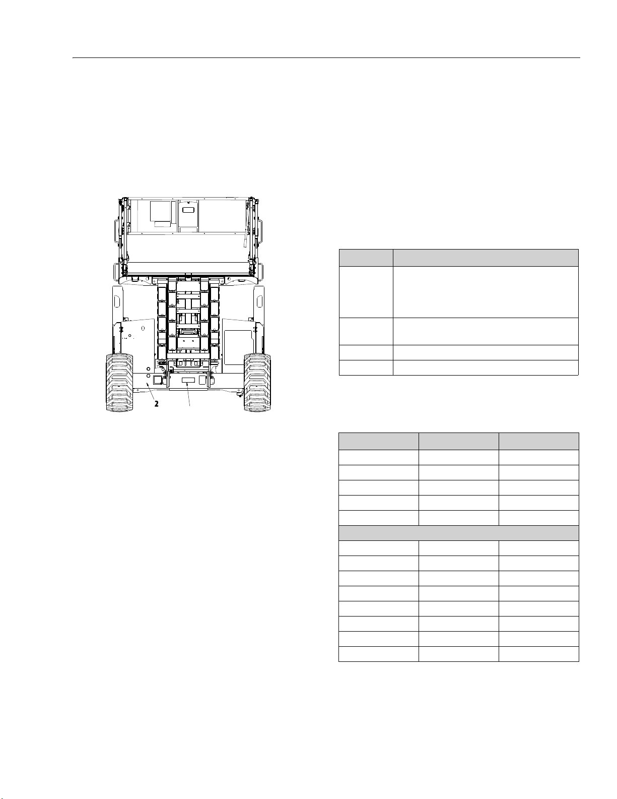
SECTION 1 - SPECIFICATIONS
1
1. Serial Number Plate
2. Stamped Serial Number
Figure 1-1. Serial Number Location
1.2 SERIAL NUMBER LOCATIONS
For machine identification, a serial number plate is
affixed to the machine. The plate is located at the rear of
the machine on the center of the axle. In addition,
should the serial number plate be damaged or missing,
the machine serial number is stamped onto the lip of
the rear axle.
1.3 LUBRICATION
NOTE: Hydraulic oils must have anti-wear qualities at least
to API Service Classification GL-3, and sufficient
chemical stability for mobile hydraulic system service.
NOTE: Aside from JLG recommendations, it is not advisable
to mix oils of different brands or types, as they may
not contain the same required additives or be of
comparable viscosities.
Table 1-9. Lubrication Specifications
KEY SPECIFICATIONS
Multipurpose Grease - Having a minimum dripping point
MPG
EPGL
EO Engine Oil (crankcase)
HO Hydraulic Oil
of 350° F. Excellent water resistance and adhesive qualities,
and being of extreme pressure type. (Timken OK 40 pounds
minimum.)
Extreme Pressure Gear Lube (oil) - Meeting API service classification GL-5 or MIL-Spec MIL-L-2105.
Hydraulic Oil Specifications
Table 1-10. Mobilfluid 424
Inspection Data Recommended Optional
SAE Grade 10W-30 10W-20
Gravity, API 29.0 29.3
Density, LB/GAL, 60° F 7.35 7.3
Flash Point, ° F(° C) 442(228) 380(193)
Pour Point, ° F(° C) -46 (-43) -30(-34)
Viscosity
Br o ok f ie ld , cP at - 18 ° C 2700
Brookfield, cP at 0° F 2500
Viscosity, cST at 40°C 55 52.1
Viscosity, cST at 100°C 9.3 8.95
Visc osit y Ind ex 152 152
Viscosity, Sus at 100°F 26.0
Viscosity, Sus at 210°F 56.8
Color, ASTM D 1500 3.0
3121781 1-3
Page 20

SECTION 1 - SPECIFICATIONS
Table 1-11. Mobil DTE 10 Excel 32
ISO Viscosity Grade 32
Pour Point , °C M ax. -54
Flash Point, °C Min. 250
Viscosity
cSt @ 40° C 32.7
cSt @ 100° C 6.63
cSt @ 100° F 32.7
cSt @ 212° F 6.63
Visco sit y In dex 164
Density (Kg/l) @ 15°C 0.8468
Density (lb/in³) @ 60°F 0.0305
Table 1-12. UCon Hydrolube HP-5046
pH 9.1
Specific Gravity, 20/20°F 1.082
Pour Point , °C( °F) <-50(<58)
Appearance Red Liquid
Viscosity
at 0°C (32°F) 340cST(1600SUS)
at 40°C (104°F) 46cST(215SUS)
at 65°C (150°F) 22cST(106SUS)
Visco sit y In dex 170
Table 1-14. Mobil SHC Hydraulic EAL 46
ISO Viscosity Grade 46
Density@15° C 0.93
Pour Po int, °C (°F), ASTM D 97 -33(-27)
Flash Point, °C (°F), Min., ASTM D 97 298(568)
Operating Temp °C(°F) -29°(-20) to 93(200)
Viscosity
ASTM D 445 cST 40°C 43.3
ASTM D 445 cST 100°C 7.7
Visco sit y In dex 149
Table 1-15. Mobil EAL ENVIROSYN H 46
ISO Viscosity Grade 46
Density@15° C 0.874
Pour Po int, °C (°F), ASTM D 97 -45°C(-49)
Flash Point, °C (°F), Min., ASTM D 97 260°C(500)
Operating Temp °C(°F) -29°(-20) to 93(200)
Viscosity
ASTM D 445 cST 40°C 48.8
ASTM D 445 cST 100°C 7.8
Visco sit y In dex 145
1.4 HYDRAULIC PRESSURE SETTINGS
Table 1-13. Mobil EAL 224H
Typ e Biodegradable Vegetable Oil
ISO Viscosity Grade 32/46
Specific Gravity 0.922
Pour Point °C( °F) -32°(-25°)
Flash Point °C(°F) 220°(428°)
Rust Protection, ASTM D 665A & BB Pass Color, ASTM D 1500 Max 2.0
Operating Temp -17°-162°C (0-180°F) (Store above14°C (32°F))
Viscosity
ASTM D445 cST 40°C 37
ASTM D445 cST 100°C 8.4
Viscosity Index, ASTM D 2270 213
Table 1-16. Main Control Valve Relief Settings
Description 530LRT
Main Relief 2700 psi (186 bar)
Steer Relief 2500 psi (172 bar)
1.5 HYDRAULIC CYLINDER SPECIFICATIONS
Table 1-17. Cylinder Specifications
Description Bore Stroke Rod Dia
L if t C y li n d e r s U p pe r :
Lower:
Leveling Jack Cylinder 2.5 in.
RAM Lockout Cylinder
(Oscillating Axle)
Steer Cylinder 2.75 in.
3.90 in.
(100 mm)
4.70 in.
(120 mm)
(63 mm)
3.62 in.
(92 mm)
(70 mm)
84.125 in.
(2137 mm)
84.125 in.
(2137 mm)
27 in.
(685.8 mm)
4 in.
(101.6 mm)
8.94 in.
(227.1 mm)
(88.9 mm)
3.30 in.
(85 mm)
3.5 in.
(90 mm)
2 in.
(50 mm)
3.5 in.
1.97 in.
(50 mm)
1-4 3121781
Page 21
SECTION 1 - SPECIFICATIONS
1.6 ENGINE SPECIFICATIONS
Table 1-18. Kubota Diesel (D1305-E4B - T4F)
Emissions CARB and EPA Tier 4 Final
Fuel Type: Diese l:
- Low Sulfur (<500 ppm)
- Ultra Low Sulfur (15 ppm)
(Recommended)
- up to 5% biodiesel
No. of Cylinders 3
Oil Pan Capacity 1.51 Gal. (5.7 L)
Engine RPM Control Mechanical
Low RPM Set 1200 RPM
High RPM Set 2600 RPM
Alternator 60 Amp, 12V, Belt Drive
Battery 112 Amp -Hour, 950 Cold Cranking Amps,
12 VDC
Fuel Consumption: Low RPM
High RPM
Displacement 1.261 L (77 cu. in.)
Gross Power 24.8 Hp (18.5 Kw) @ 2600 RPM
Gross Torque 59.1 Ft. lb. (80.1 Nm) @ 1700 RPM
Table 1-19. Kubota (D1305-E3B - Stage IIIA - Diesel)
Emissions China Stage III and EU Stage IIIA Certifica-
Fuel Type: Diese l:
No. of Cylinders 3
Oil Pan Capacity 1.51 Gal. (5.7 L)
Engine RPM Control Mechanical
Low RPM Set 1200 RPM
High RPM Set 3000 RPM
Alternator 60 Amp, 12V, Belt Drive
Battery 112 Amp-Hour, 950 Cold Cranking Amps,
Fuel Consumption:
Low RP M
High RPM
Displacement 1.261 L (77 cu. in.)
Gross Power 29.1 Hp (21.7 Kw) @ 3000 RPM
Gross Torque 59.1 Ft. lb. (80.1 Nm) @ 2000 RPM
0.41 gal/hr (1.5 L/hr)
2.0 gal/hr (7.6 L/hr)
tion
- Low Sulfur (<500 ppm)
- Ultra Low Sulfur (15 ppm)
(Recommended)
- up to 5% biodiesel
12 VDC
0.41 gal/hr (1.5 L/hr)
2.0 gal/hr (7.6 L/hr)
Table 1-20. Kubota (WG972-GL-E4 - Dual Fuel)
Emissions U.S. EPA Phase 3 and CARB SSI
Fuel Type: Gasoline - 87 Octane minium
- Ethanol/Gas Mix-10% max.
- Methanol/Gas Mix-5% max.
LP - Liquid Petrolium
No. of Cylinders 3
Oil Pan Capacity 0.90 Gal. (3.4 L)
Engine RPM Control Electronic - ECM
Low RPM Set 1200 RPM
High RPM Set 3500 RPM
Alternator 60 Amp, 12V, Belt Drive
Battery 112 Amp-Hour, 950 Cold Cranking
Amps, 12 VDC
Fuel Consumption:
Low RPM
0.38 gal/hr (1.45 L/hr) - Gas
2.07 lb/hr (0.94 kg/hr) - LP
High RPM
1.76 gal/hr (6.66 L/hr) - Gas
9.77 lb/hr (4.43 kg/hr) - LP
Displacement 0.962L (58.7 cu. in.)
Gross Power GAS - 30.6 Hp (22.8 Kw) @ 3500 RPM
LP - 30.0 Hp (21.6 Kw) @ 3500 RPM
Gross Torque GAS - 49.1 Ft.lb (66.6 Nm) @ 2400
RPM
LP - 48.8 Ft.lb (66.2 Nm) @ 1800 RPM
3121781 1-5
Page 22
SECTION 1 - SPECIFICATIONS
1.7 PLATFORM HEIGHT/TILT LIMIT SETTINGS
The machine is equipped with the following limit
switches:
Rotary Position Sensor - High drive speed is cut out
when platform is raised above the preset heights listed in
Table 1-21, Maximum Cutout Height.
Table 1-21. Maximum Cutout Height
Model High Drive Cutout
530LRT 14 ft (4.26 m)
Tilt Alarm - An alarm sounds and a warning light is illuminated when the machine is operated on a slope that
exceeds the values in Table 1-22, Tilt Cutout Settings.
The lift and drive functions will cut out at these set
heights.
NOTE: Alarm only sounds when above elevation.
If the machine is operated beyond the specified
slope, with the platform completely lowered, only
the warning light is illuminated.
Table 1-22. Tilt Cutout Settings
Leveling Jacks Set Leveling Jacks NOT Set
Market
ANSI,ANSI Exp.,
CE, AUS, Korea
CSA 1.5° to 53 ft (16 m) 1.5° to 53 ft (16 m) 3° to 32 ft (9.75 m) 3° to 32 ft (9.75 m) 32 ft 32 ft
Front to Back Side to Side Front to Back Side to Side
1.5° to 53 ft (16 m) 1.5° to 53 ft (16 m)
5° to 32 ft (9.75 m)
1.3° to 45 ft (13.7 m)
3° to 32 ft (9.75 m)
1.3° to 45 ft (13.7 m)
Drive is prevented
when elevated
beyond the
following heights:
32 ft 45 ft
beyond the following
Lift Up is prevented
when elevated
heights without
leveling jacks set:
1-6 3121781
Page 23
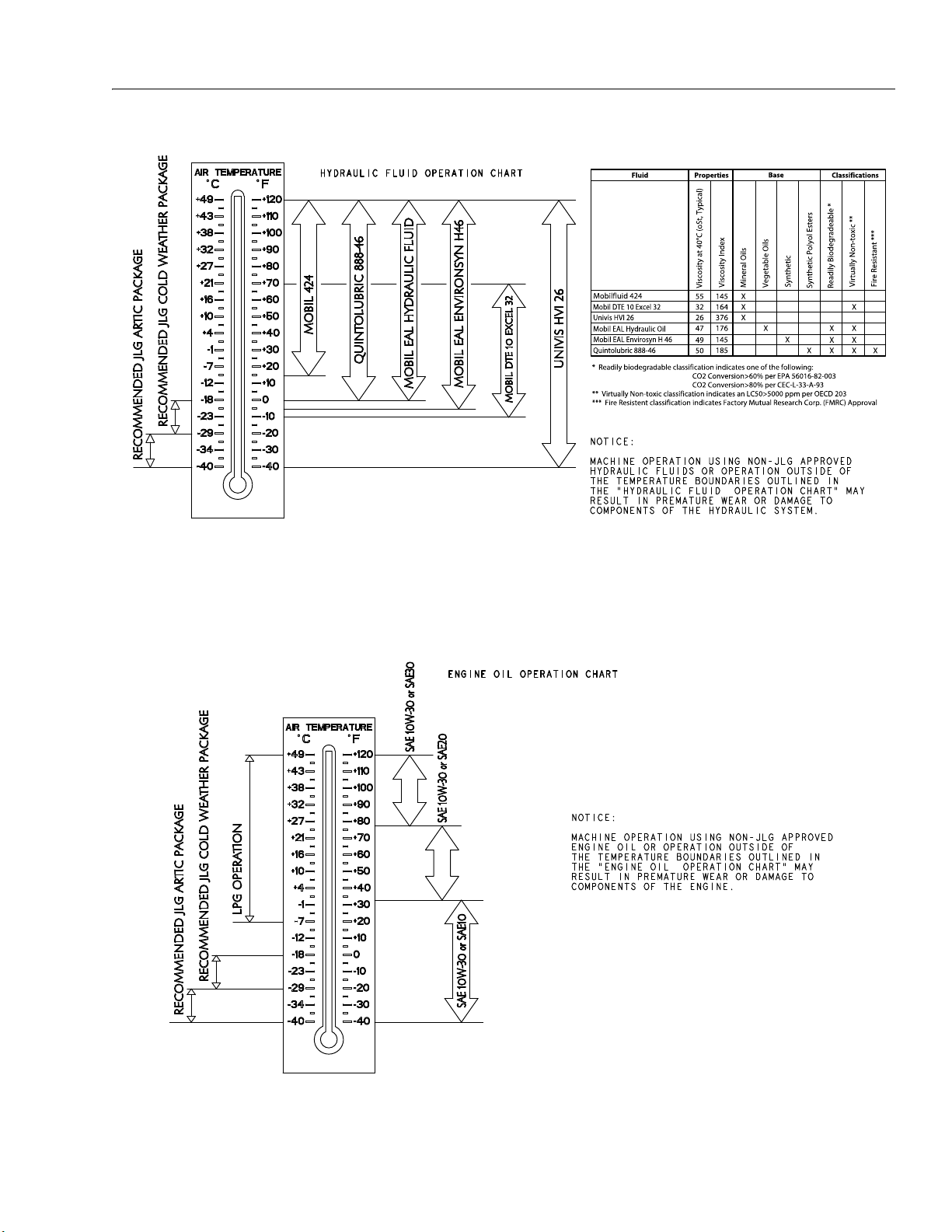
SECTION 1 - SPECIFICATIONS
4150740_B_Hydraulic
Figure 1-2. Hydraulic Oil Operating Temperature Specifications
1001204714_A_Dual Fuel
Figure 1-3. Engine Oil Operating Temperature Specifications - Kubota (Dual Fuel Engine)
3121781 1-7
Page 24
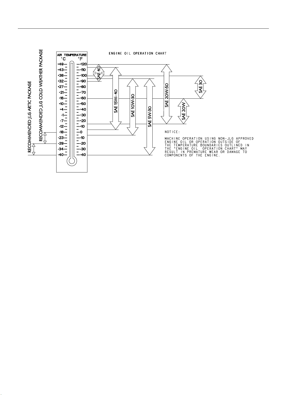
SECTION 1 - SPECIFICATIONS
1001120075_C_Diesel
Figure 1-4. Engine Oil Operating Temperature Specifications - Kubota (Diesel Engine)
1-8 3121781
Page 25
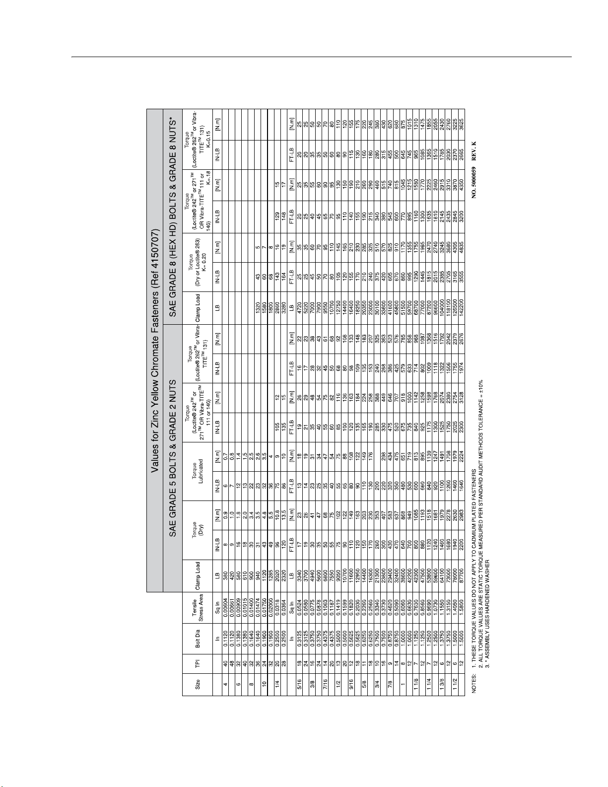
1.8 TORQUE CHARTS
SECTION 1 - SPECIFICATIONS
Figure 1-5. Torque Chart - Sheet 1 of 5 - (SAE Fasteners)
3121781 1-9
Page 26
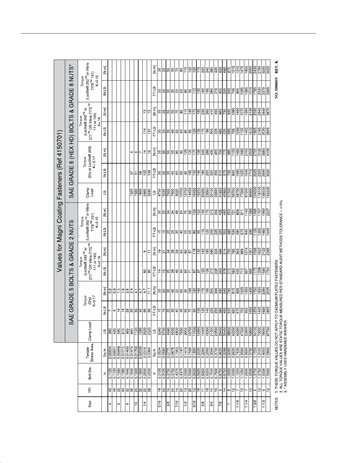
SECTION 1 - SPECIFICATIONS
Figure 1-6. Torque Chart - Sheet 2 of 5 - (SAE Fasteners)
1-10 3121781
Page 27
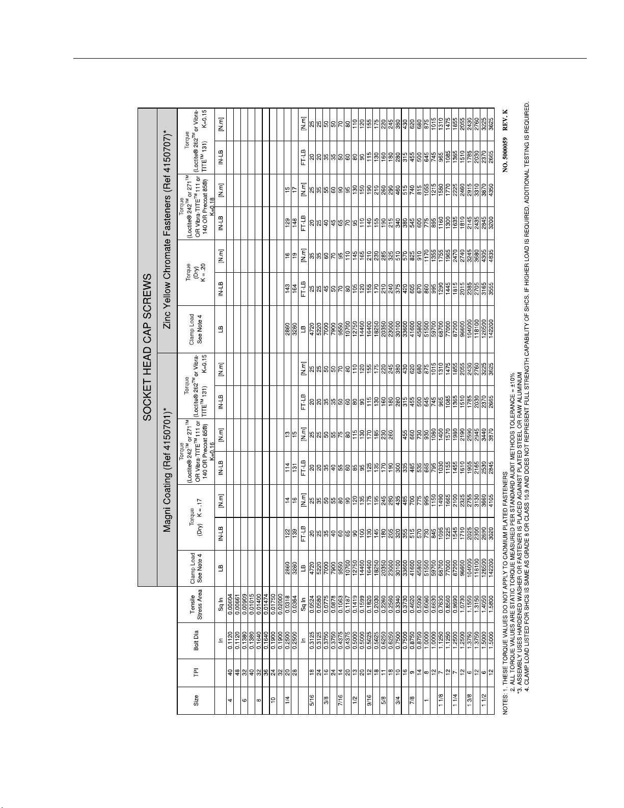
SECTION 1 - SPECIFICATIONS
Figure 1-7. Torque Chart - Sheet 3 of 5 - (SAE Fasteners)
3121781 1-11
Page 28
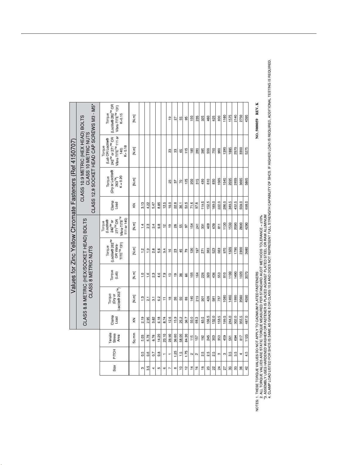
SECTION 1 - SPECIFICATIONS
Figure 1-8. Torque Chart - Sheet 4 of 5 - (METRIC Fasteners)
1-12 3121781
Page 29
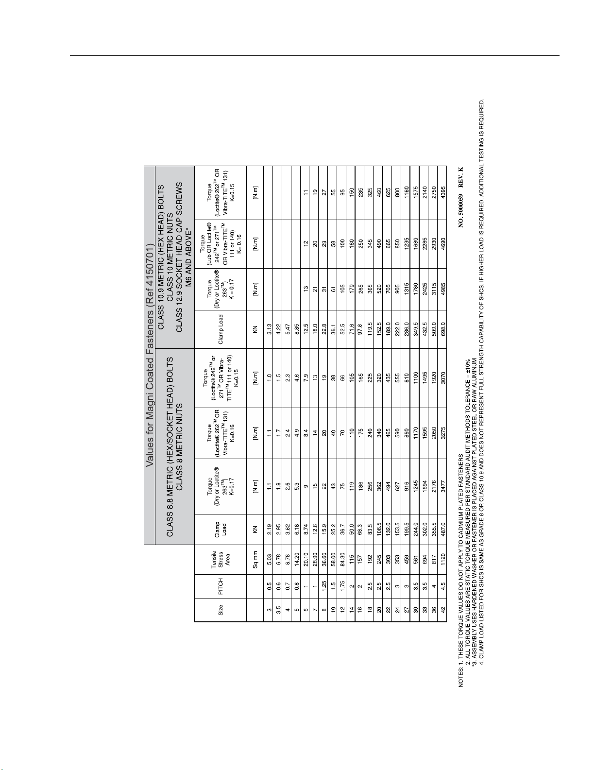
SECTION 1 - SPECIFICATIONS
Figure 1-9. Torque Chart - Sheet 5 of 5 - (METRIC Fasteners)
3121781 1-13
Page 30

SECTION 1 - SPECIFICATIONS
NOTES:
1-14 3121781
Page 31

SECTION 2. GENERAL
SECTION 2 - GENERAL
2.1 MACHINE PREPARATION, INSPECTION, AND MAINTENANCE
General
This section provides the necessary information needed
by those personnel that are responsible to place the
machine in operation readiness and maintain its safe
operating condition. For maximum service life and safe
operation, ensure that all the necessary inspections and
maintenance have been completed before placing the
machine into service. With proper care, maintenance
and inspections performed per JLG's recommendations
with any and all discrepancies corrected, this product
will be fit for continued use.
Preparation, Inspection, and Maintenance
It is important to establish and conform to a comprehensive inspection and preventive maintenance program. The following table outlines the periodic machine
inspections and maintenance recommended by JLG
Industries, Inc. Consult your national, regional, or local
regulations for further requirements for aerial work platforms. The frequency of inspections and maintenance
must be increased as environment, severity and frequency of usage requires.
Pre-Start Inspection
It is the User’s or Operator’s primary responsibility to
perform a Pre-Start Inspection of the machine prior to
use daily or at each change of operator. Reference the
Operator’s and Safety Manual for completion procedures for the Pre-Start Inspection. The Operator and
Safety Manual must be read in its entirety and understood prior to performing the Pre-Start Inspection.
Pre-Delivery Inspection and Frequent Inspection
The Pre-Delivery Inspection and Frequent Inspection
shall be performed by a qualified JLG equipment
mechanic. JLG Industries, Inc. recognizes a qualified JLG
equipment mechanic as a person who, by possession of
a recognized degree, certificate, extensive knowledge,
training, or experience, has successfully demonstrated
the ability and proficiency to service, repair, and maintain the subject JLG product model.
The Pre-Delivery Inspection and Frequent Inspection
procedures are performed in the same manner, but at
different times. The Pre-Delivery Inspection shall be performed prior to each sale, lease, or rental delivery. The
Frequent Inspection shall be accomplished for each
machine in service for 3 months or 150 hours (whichever comes first); out of service for a period of more than
3 months; or when purchased used. The frequency of
this inspection must be increased as environment,
severity and frequency of usage requires.
Reference the JLG Pre-Delivery and Frequent Inspection
Form and the Inspection and Preventative Maintenance
Schedule for items requiring inspection during the performance of these inspections. Reference the appropriate areas of this manual for servicing and maintenance
procedures.
Annual Machine Inspection
JLG recommends that an annual machine inspection be
performed by a Factory-Certified Service Technician on
an annual basis, no later than thirteen (13) months from
the date of the prior Annual Machine Inspection. JLG
Industries, Inc. recognizes a Factory-Certified Service
Technician as a person who has successfully completed
the JLG Service Training School for the subject JLG product model. Reference the machine Service and Maintenance Manual and appropriate JLG inspection form for
performance of this inspection.
Reference the JLG Annual Machine Inspection Form and
the Inspection and Preventative Maintenance Schedule
for items requiring inspection during the performance
of this inspection. Reference the appropriate areas of
this manual for servicing and maintenance procedures.
For the purpose of receiving safety-related bulletins, it is
important that JLG Industries, Inc. has updated ownership information for each machine. When performing
each Annual Machine Inspection, notify JLG Industries,
Inc. of the current machine ownership.
Preventative Maintenance
In conjunction with the specified inspections, maintenance shall be performed by a qualified JLG equipment
mechanic. JLG Industries, Inc. recognizes a qualified JLG
equipment mechanic as a person who, by possession of
a recognized degree, certificate, extensive knowledge,
training, or experience, has successfully demonstrated
the ability and proficiency to service, repair, and maintain the subject JLG product model.
Reference the Preventative Maintenance Schedule and
the appropriate areas of this manual for servicing and
maintenance procedures. The frequency of service and
maintenance must be increased as environment, severity and frequency of usage requires.
3121781 2-1
Page 32

SECTION 2 - GENERAL
Table 2-1. Inspection and Maintenance
Type Frequency
Pre-Star t
Inspection
Pre-Delivery
Inspection
Frequent
Inspection
Annual
Machine
Inspection
Preventative
Maintenance
Pr i or to u se e ac h da y; o r
At each Operator change.
Prior to each sale, lease, or
rental d elivery.
In service for 3 months or 150 hours, whichever
comes first; or Out of service for a period of more
than 3 months; or Purchased used.
Annually, no later than 13 months from the date
of the prior inspection. Owner, Dealer, or User
At intervals as specified in the Service and Maintenance Manual.
Primary
Responsibility
User or Operator User or Operator Operator and Safety Manual
Owner, Dealer, or User Qualified JLG Mechanic
Owner, Dealer, or User Qualified JLG Mechanic
Owner, Dealer, or User Qualified JLG Mechanic Service and Maintenance Ma nual
2.2 PREVENTIVE MAINTENANCE AND INSPECTION SCHEDULE
The preventive maintenance and inspection checks are
listed and defined in the following table. This table is
divided into two basic parts, the “AREA” to be inspected
and the “INTERVAL” at which the inspection is to take
place. Under the “AREA” portion of the table, the various
systems along with the components that make up that
system are listed. The “INTERVAL” portion of the table is
divided into two columns representing the various
inspection time periods. The numbers listed within the
interval column represent the applicable inspection
code for which that component is to be checked.
The checks and services listed in this schedule are not
intended to replace any local or regional regulations
that may pertain to this type of equipment nor should
the lists be considered as all inclusive. Variances in interval times may occur due to climate and/or conditions
and depending on the location and use of the machine.
JLG INDUSTRIES REQUIRES THAT A COMPLETE ANNUAL INSPECTION
BE PERFORMED IN ACCORDANCE WITH THE "ANNUAL MACHINE
INSPECTION REPORT” FORM.
NOTE: This machine requires periodic safety and mainte-
nance inspections by a JLG Dealer. A decal located
on the frame affords a place to record (stamp)
inspection dates. Notify dealer if inspection is overdue.
Service
Qualification
Factory-Certified Ser vice
Technician or a Qualified
JLG Mechanic
Service and Maintenance Manual and
Service and Maintenance Manual and
Service and Maintenance Manual and
Reference
applicable JLG inspection form.
applicable JLG inspection form.
applicable JLG inspection form.
Maintenance and Inspection Schedule Codes
1. Check for proper and secure installation.
2. Visual inspection for damage, cracks, distortion, or
excessive wear.
3. Check for proper adjustment.
4. Check for cracked or broken welds.
5. Operates properly.
6. Returns to neutral or “off” position when released.
7. Clean and free of debris.
8. Interlocks function properly.
9. Check for signs of leakage.
10. Decals installed and legible.
11. Check for proper fluid level.
12. Check for chafing and proper routing.
13. Check for proper tolerances.
14. Properly lubricated.
15. Torqued to proper specification.
16. No gouges, excessive wear, or cords showing.
17. Properly inflated and seated around rim.
18. Proper and authorized components.
19. Fully charged.
20. No loose connections, corrosion, or abrasions.
21. Verify.
22. Perform.
23. Sealed properly.
24. Overrides platform controls.
25. Remove pump motor cover and blow away any
brush wear dust from cover, brushes, and brush
holder assembly.
26. Replace.
2-2 3121781
Page 33

Table 2-2. Preventive Maintenance & Inspection Schedule
INTERVAL
SECTION 2 - GENERAL
AREA ON MACHINE
FUNCTIONS/CONTROLS
Platform Controls 5, 6, 7 5, 6, 7
Ground Controls 5, 6 5, 6
Function Control, Guards, or Detents 5 5
Funct ion Enab le System 5, 8 5, 8
Emergency Stop Switches (Ground & Platform) 5 5
Manual Descent or Auxiliar y Power 5 5
PLATFORM ASSEMBLY
Platform 1 1
Guard Rails 1, 2, 4 1, 2, 4
Gate 1, 5 1, 5
Floor 1, 2 1, 2
Lanyard Anchorage Point 1, 4, 10 1, 4, 10
SCISSOR ARMS
Scissor Arms 1, 2, 4 1, 2, 4
Arm Safety Prop 1 , 5 1, 5
Cylinder Pins, Pivot Pins & Attaching Hardware 1, 2 1, 2
Arm Pins, Wear Pads & Attaching Hardware 1, 2 1, 2
CHASSIS ASSEMBLY
Side-Compartment Door Installation 1, 5,7 1, 5, 7
Static Strap 1 1
Wheel and Tire Assemblies 2, 15, 16 2, 15, 16
Drive Motors 1, 7, 9 1, 7, 9
Platform Ladder 1, 7 1, 7
Drive Brakes 1, 7 1, 7
Drive Torque Hubs 1, 7 1, 7
Engine Mounts 1 1
Battery 9 18
Engine Oil 5 5
Exhaust System 1, 5 1, 5
Fuel Tank 1, 9 1, 9
Air Cleaner**** 7 26
PRE-DELIVERY (a)
OR FREQUENT (b)
INSPECTION
ANNUAL (c)
(YEARLY)
INSPECTION
3121781 2-3
Page 34

SECTION 2 - GENERAL
Table 2-2. Preventive Maintenance & Inspection Schedule (Continued)
INTERVAL
AREA ON MACHINE
HYDRAULIC/ELECTRIC SYSTEM
Hydraulic Pump 1, 2, 9 1, 2, 9
Hydraulic Control Valves 1, 9 1, 9
Hydraulic Fluid*** 11 11
Hydraulic Filter* — 26
Hydraulic Hoses, Lines and Fittings 1, 9 1, 9
Hydraulic Oil Tank, Cap, and Breather 5, 7, 9 5, 7, 9
Hydraulic Cylinders (Steer and Lift) 2, 7, 9 2, 7, 9
GENERAL
Operation & Safet y Manual in Storage Box 21 21
ANSI & AEM Handbooks in Storage Box (ANSI ONLY) 21 21
Capacity Decals Installed, Secure, Legible 21 21
All Decals/Placards Installed, Secure, Legible 21 21
Annual Machine Inspection Due — 21
No Unauthorized Modifications or Additions 21 21
All Relevant Safety Publications Incorporated 21 21, 22
General Structural Condition and Welds 2, 4 2, 4
All Fasteners, Pins, Shields, and Covers 1, 2 1, 2
Grease and Lubricate to Specifications 22 22
Function Test of All Systems 22 22
Paint and Appearance 7 7
Notify JLG of change in Machine Ownership 22
PRE-DELIVERY (a)
OR FREQUENT (b)
INSPECTION
ANNUAL (c)
(YEARLY)
INSPECTION
* Replace Annually - JLG P/N - 70005423.
** Replace when system performance is degraded.
*** Every two years, drain and remove hydraulic oil reservoir, clean pick-up screen, refill with fresh hydraulic fluid.
**** Replace every six (6) months.
Footnotes
(a) Prior to each sale, lease, or delivery.
(b) In service for 3 months; or Out of service for 3
months or more; or Purchased used.
(c) Annually, no later than 13 months from the date of
the prior inspection.
2-4 3121781
Page 35

SECTION 2 - GENERAL
2.3 SERVICE AND GUIDELINES
General
The following information is provided to assist you in
the use and application of servicing and maintenance
procedures contained in this book.
Safety and Workmanship
Your safety, and that of others, is the first consideration
when engaging in the maintenance of equipment.
Always be conscious of weight. Never attempt to move
heavy parts without the aid of a mechanical device. Do
not allow heavy objects to rest in an unstable position.
When raising a portion of the equipment, ensure that
adequate support is provided.
Cleanliness
1. The most important single item in preserving the
long service life of a machine is to keep dirt and foreign materials out of the vital components. Precautions have been taken to safeguard against this.
Shields, covers, seals, and filters are provided to keep
air, fuel, and oil supplies clean; however, these items
must be maintained on a scheduled basis in order to
function properly.
2. At any time when air, fuel, or oil lines are disconnected, clear adjacent areas as well as the openings
and fittings themselves. As soon as a line or component is disconnected, cap or cover all openings to
prevent entry of foreign matter.
3. Clean and inspect all parts during servicing or maintenance, and assure that all passages and openings
are unobstructed. Cover all parts to keep them clean.
Be sure all parts are clean before they are installed.
New parts should remain in their containers until
they are ready to be used.
Components Removal and Installation
4. Use adjustable lifting devices, whenever possible, if
mechanical assistance is required. All slings (chains,
cables, etc.) should be parallel to each other and as
near perpendicular as possible to top of part being
lifted.
5. Should it be necessary to remove a component on an
angle, keep in mind that the capacity of an eyebolt or
similar bracket lessens, as the angle between the
supporting structure and the component becomes
less than 90°.
6. If a part resists removal, check to see whether all
nuts, bolts, cables, brackets, wiring, etc., have been
removed and that no adjacent parts are interfering.
Component Disassembly and Reassembly
When disassembling or reassembling a component,
complete the procedural steps in sequence. Do not partially disassemble or assemble one part, then start on
another. Always recheck your work to assure that nothing has been overlooked. Do not make any adjustments,
other than those recommended, without obtaining
proper approval.
Pressure-Fit Parts
When assembling pressure-fit parts, use an anti-seize or
molybdenum disulfide base compound to lubricate the
mating surface.
Bearings
1. When a bearing is removed, cover it to keep out dirt
and abrasives. Clean bearings in nonflammable
cleaning solvent and allow to drip dry. Compressed
air can be used but do not spin the bearing.
2. Discard bearings if the races and balls (or rollers) are
pitted, scored, or burned.
3. If bearing is found to be serviceable, apply a light
coat of oil and wrap it in clean (waxed) paper. Do not
unwrap reusable or new bearings until they are
ready to install.
4. Lubricate new or used serviceable bearings before
installation. When pressing a bearing into a retainer
or bore, apply pressure to the outer race. If the bearing is to be installed on a shaft, apply pressure to the
inner race.
Gaskets
Check that holes in gaskets align with openings in the
mating parts. If it becomes necessary to hand-fabricate
a gasket, use gasket material or stock of equivalent
material and thickness. Be sure to cut holes in the right
location, as blank gaskets can cause serious system
damage.
Bolt Usage and Torque Application
1. Use bolts of proper length. A bolt which is too long
will bottom before the head is tight against its
related part. If a bolt is too short, there will not be
enough thread area to engage and hold the part
properly. When replacing bolts, use only those having the same specifications of the original, or one
which is equivalent.
3121781 2-5
Page 36

SECTION 2 - GENERAL
2. Unless specific torque requirements are given within
the text, standard torque values should be used on
heat-treated bolts, studs, and steel nuts, in accordance with recommended shop practices. (See
Torq u e C h a r t Section 1.)
Hydraulic Lines and Electrical Wiring
Clearly mark or tag hydraulic lines and electrical wiring,
as well as their receptacles, when disconnecting or
removing them from the unit. This will assure that they
are correctly reinstalled.
Hydraulic System
1. Keep the system clean. If evidence of metal or rubber
particles are found in the hydraulic system, drain and
flush the entire system.
2. Disassemble and reassemble parts on clean work
surface. Clean all metal parts with non-flammable
cleaning solvent. Lubricate components, as required,
to aid assembly.
Lubrication
Service applicable components with the amount, type,
and grade of lubricant recommended in this manual, at
the specified intervals. When recommended lubricants
are not available, consult your local supplier for an
equivalent that meets or exceeds the specifications
listed.
Battery
Clean battery, using a non-metallic brush and a solution
of baking soda and water. Rinse with clean water. After
cleaning, thoroughly dry battery and coat terminals
with an anti corrosion compound.
Lubrication and Servicing
2.4 LUBRICATION AND INFORMATION
Hydraulic System
1. The primary enemy of a hydraulic system is contamination. Contaminants enter the system by various
means, e.g., using inadequate hydraulic oil, allowing
moisture, grease, filings, sealing components, sand,
etc., to enter when performing maintenance, or by
permitting the pump to cavitate due to insufficient
system warm-up or leaks in the pump supply (suction) lines.
2. The design and manufacturing tolerances of the
component working parts are very close, therefore,
even the smallest amount of dirt or foreign matter
entering a system can cause wear or damage to the
components and generally results in faulty operation. Every precaution must be taken to keep hydraulic oil clean, including reserve oil in storage. Hydraulic
system filters should be checked, cleaned, and/or
replaced as necessary, at the specified intervals
required in the Lubrication Chart in Section 1. Always
examine filters for evidence of metal particles.
3. Cloudy oils indicate a high moisture content which
permits organic growth, resulting in oxidation or corrosion. If this condition occurs, the system must be
drained, flushed, and refilled with clean oil.
4. It is not advisable to mix oils of different brands or
types, as they may not contain the same required
additives or be of comparable viscosities. Good
grade mineral oils, with viscosities suited to the
ambient temperatures in which the machine is operating, are recommended for use.
NOTE: Metal particles may appear in the oil or filters of new
machines due to the wear-in of meshing components.
Components and assemblies requiring lubrication and
servicing are shown in the Lubrication Chart in Section
1.
2-6 3121781
Page 37

SECTION 2 - GENERAL
1
Changing Hydraulic Oil
1. Use of any of the recommended hydraulic oils eliminates the need for changing the oil on a regular
basis. However, filter elements must be changed
after the first 50 hours of operation and every 300
hours thereafter. If it is necessary to change the oil,
use only those oils meeting or exceeding the specifications appearing in this manual. If unable to
obtain the same type of oil supplied with the
machine, consult local supplier for assistance in
selecting the proper equivalent. Avoid mixing
petroleum and synthetic base oils. JLG Industries
recommends changing the hydraulic oil annually.
2. Use every precaution to keep the hydraulic oil
clean. If the oil must be poured from the original
container into another, be sure to clean all possible
contaminants from the service container. Always
clean the mesh element of the filter and replace the
cartridge any time the system oil is changed.
3. While the unit is shut down, a good preventive
maintenance measure is to make a thorough inspection of all hydraulic components, lines, fittings, etc.,
as well as a functional check of each system, before
placing the machine back in service.
Lubrication Specifications
Specified lubricants, as recommended by the component manufacturers, are always the best choice, however, multi-purpose greases usually have the qualities
which meet a variety of single purpose grease requirements. Should any question arise, regarding the use of
greases in maintenance stock, consult your local supplier for evaluation. Refer to Section 1 for an explanation
of the lubricant key designations appearing in the Lubrication Chart.
2.5 SERVICE MAINTENANCE COMPONENTS
Setting Scissor Arm Safety Prop
THE SAFETY PROP MUST BE USED WHENEVER MAINTENANCE PERFORMED ON THE MACHINE REQUIRES THE SCISSOR ARMS TO BE
RAISED.
1. To engage the safety props, raise the unloaded
platform high enough to allow the safety props to
rotate vertically into position. (See Figure 2-1.)
2. Rotate the rod keeper plate and release the safety
prop actuator rod at the front of the machine. (See
Figure 2-2.)
3. Lift the actuator rod (flat) up out of the slot in the
keeper plate bracket and pull the actuator rod to
align the safety props vertically with the scissor arm
center pins above and below the safety prop
mounting pins.
4. Set the actuator rod (flat at the set position) into
the slot on the keeper plate bracket and rotate the
keeper plate to lock the actuator rod in this position.
5. Lower the platform arms until the safety prop rests
on the scissor arm center pin mounts above and
below the safety prop.
Maintenance can now begin.
Figure 2-1. Scissor Arm - Safety Prop Assembly
1. Actuator Rod/Rod Keeper Plate.
2. Safety Prop in set position.
To store the safety prop, raise the platform, release
3121781 2-7
the actuator rod from the keeper plate bracket, push
the safety prop rod so that the safety props are
3. Safety Prop in stowed position.
Page 38

SECTION 2 - GENERAL
1
1
4
5
3
9
4
5
6
8
4
10
5
MAF04540
2
7
11
restored back to its stowed position. Lock the actuator rod in place with the keeper plate till next use.
TO AVOID PERSONAL INJURY, USE SAFETY PROP FOR ALL MAINTENANCE REQUIRING PLATFORM TO BE ELEVATED.
Figure 2-2. Safety Prop Actuator Rod
1. Safety Prop Actuator
3. Rod Keeper Plate
Rod
2. Notch Flats on Rod
General Maintenance Tips
NOTE: Be sure to lubricate like items on each side of
machine.
NOTE: Recommended lubricating intervals are based on
machine operations under normal conditions. For
machines used in multi-shift operations and/or
exposed to hostile environments or conditions,
lubrication frequencies must be increased accordingly.
Operate hydraulic functions through one complete
cycle before checking hydraulic oil level in tank. Oil
should be visible in ADD sight window on hydraulic
tank. If oil is not visible, add oil until oil is visible in
both ADD and FULL sight windows on tank. Do not
overfill tank.
Any time the pump coupling is removed, coat
splines of coupling with Texaco Code 1912 grease
prior to assembly.
1. Fuel Tank - (Gasoline or Diesel)
2. Fuel Tank w/Shut-Off Valve - (LP Only)
3. Hydraulic Oil Tank
4. Drive Hubs
2-8 3121781
5. Scissor Arm - Sliding Wear Pads
6. Oil Change w/Filter - Kubota
7. Fuel/Water Separator Filter - Kubota- Diesel
8. Hydraulic Charge Filter - Kubota - Diesel
Figure 2-3. Service Maintenance Components
NOTE: Platform ladders removed for illustrative purposes only.
9. Fuel Filter/Fuel Pump - Kubota- Gasoline
10. Air Filter
11. Engine Coolant
Page 39

SECTION 2 - GENERAL
OAD00220
Fuel Tank
• Fuel - Diesel or Gasoline (Per Engine Type - Reference Decal on Machine)
• Capacity - 22 gal (83.2 l)
Drive Hub
Hydraulic Oil Tank
• Lube Point - Fill Cap/Fill Level
• Lube - HO - API service classification GL-3, Reference - Figure 1-2., Hydraulic Oil Operating Temperature Specifications
• Interval - Check oil every 10 hours of operation;
change oil every 2 years or 1200 hours of operation.
Hydraulic Charge Filter
• Lube Points - Fill Plugs (4)
•Lube - EPGL
• Interval - Every 2 years or 1200 hours
Scissor Arms - Sliding Wear Pads
• Lube Points - 8 Sliding Wear Pads
• Lube - MPG
• Interval - Every month or 50 hours.
3121781 2-9
• Lube Point(s) - Replaceable Element
• Interval - Change after first 50 hours and after every
six months or 300 hours.
Page 40

SECTION 2 - GENERAL
1
1
Oil Change with Filter
Figure 2-4. Kubota Dual Fuel (WG972-GL-E4)
NOTE: Exhaust system shown removed for illustrative pur-
poses only.
• Lube Point(s) - Fill Cap/Spin-on Element
• Capacity - 0.9 Gal. (3.4 L) engine only
• Lube - EO - Minimum API SL, Viscosity - See Figure
1-3., Engine Oil Operating Temperature Specifications - Kubota (Dual Fuel Engine)
• Interval - Every Year or 200 hours of operation
• Check oil level daily, maintain within marked level
(1)/Change in accordance with engine manual.
Fuel/Water Separator Filter (Diesel) - Kubota
NOTE: Mounted inside engine cabinet on right-rear cabi-
net wall behind battery and exhaust pipe.
• Lube Point(s) - Replaceable Element
• Interval (Filter) - Every Year or 600 hours of operation.
• Interval (Water Bowl) - Empty Daily. Loosen drain
cock on underside of fuel filter and allow all water
to drain into a container until clear fuel is visible.
Tighten drain.
Figure 2-5. Kubota Diesel (D1305-E3B - Stage IIIA and
D1305-E4B - T4F)
• Lube Point(s) - Fill Cap/Spin-on Element
• Capacity - 1.51 gal. (5.7 L) Engine Oil
• Lube - EO - Minimum API CF - Viscosity, See Figure
1-4., Engine Oil Operating Temperature Specifications - Kubota (Diesel Engine)
• Interval - Every Year or 200 hours of operation
• Check oil level daily, maintain within marked level
(1)/Change in accordance with engine manual.
Fuel Strainer (Diesel) - Kubota
NOTE: Mounted inside fuel/hydraulic cabinet on left-rear
cabinet wall behind fuel tank.
• Lube Point(s) - Replaceable Element
• Interval - Every Year or 600 hours of operation
2-10 3121781
Page 41

SECTION 2 - GENERAL
1
MAF06110
1
Fuel Filter (Gas) - Kubota
NOTE: Mounted inside fuel/hydraulic cabinet on left-rear
cabinet wall behind fuel tank.
• Lube Point(s) - Replaceable Element
• Interval - Every 6 months or 300 hours of operation
Air Filter
Engine Coolant
• Lube Point - Fill Cap/Fill Level
• Interval - Check coolant level daily. Ensure it is
between the “FULL” and “LOW” lines (1). If coolant
level is low, allow fluid to cool, then add as required.
• Lube Point(s) - Replaceable Primary Filter Element
(1) (Dry Type)
• Interval - Every 6 months or 300 hours of operation. Under severe operating conditions (such as a
very dusty work area) check condition of filter
more often.
• Once a week, squeeze the evacuator valve (2) on
bottom of air cleaner assembly to allow collected
debris to fall out of the air cleaner.
3121781 2-11
Page 42

SECTION 2 - GENERAL
2.6 CYLINDER DRIFT TEST
Maximum acceptable cylinder drift is to be measured
using the following methods.
Platform Drift
Measure the drift of the platform to the ground. Fully
extend the scissor arms from stowed position with the
rated load in the platform and power off. Maximum
allowable drift is 2 in (5 cm) in 10 minutes. If the
machine does not pass this test, proceed with the following.
Cylinder Drift
Table 2-3. Cylinder Drift
CYLINDER BORE DIAMETER
inches mm inches mm
3 76.2 0.026 0.66
3.5 89 0.019 0.48
4 101.6 0.015 0.38
5 127 0.009 0.22
6 152.4 0.006 0.15
7 177.8 0.005 0.13
MAX. ACCEPTABLE DRIFT
IN 10 MINUTES
2.7 PINS AND COMPOSITE BEARING REPAIR GUIDELINES
Filament wound bearings.
1. Pinned joints should be disassembled and inspected if
the following occurs:
a. Excessive sloppiness in joints.
b. Noise originating from the joint during opera-
tion.
2. Filament wound bearings should be replaced if any
of the following is observed:
a. Frayed or separated fibers on the liner surface.
b. Cracked or damaged liner backing.
c. Bearings that have moved or spun in their
housing.
d. Debris embedded in liner surface.
3. Pins should be replaced if any of the following is
observed (pin should be properly cleaned prior to
inspection):
a. Detectable wear in the bearing area.
b. Flaking, pealing, scoring, or scratches on the
pin surface.
c. Rusting of the pin in the bearing area.
4. Re-assembly of pinned joints using filament wound
bearings.
Drift is to be measured at the cylinder rod with a calibrated dial indicator. The cylinder oil must be at ambient temperature and temperature stabilized.
The cylinder must have the normal load, which is the
normal platform load applied.
If the cylinder passes this test, it is acceptable.
NOTE: This information is based on 6 drops per minute cyl-
inder leakage.
a. Housing should be blown out to remove all
dirt and debris...bearings and bearing housings must be free of all contamination.
b. Bearing / pins should be cleaned with a sol-
vent to remove all grease and oil...filament
wound bearing are a dry joint and should not
be lubricated.
c. Pins should be inspected to ensure it is free of
burrs, nicks, and scratches which would damage the bearing during installation and operation.
2-12 3121781
Page 43

SECTION 3 - CHASSIS, PLATFORM & SCISSOR ARMS
SECTION 3. CHASSIS, PLATFORM & SCISSOR ARMS
3.1 OPERATING CHARACTERISTICS
Leveling Jacks
The machine is equipped with auto leveling jacks. These
leveling jacks are operated through one switch unlike
the traditional four switch system. The leveling jacks are
operated by a bang bang valve.
1. Activate the leveling jack button located on the platform control box.
2. Extend the jacks by moving the joystick forward.
NOTE: Once all four jacks make contact with the ground the
system will go from set mode into level mode. At this
point the engine will return to idle.
3. The tilt indicator will go out once the machine is
level.
NOTE: If the machine is not level it will not lift. If you hit the
end of stroke on any of the cylinders you cannot lift
the machine.
NOTE: There is a limit switch on each cylinder that senses
when the cylinder is fully retracted when all four are
fully retracted, the stowed light in the platform control box will light.
If you receive a 2/5 flash code through the system
fault light at the platform control station the
machine is unable to level. You must reposition and
try again.
The jacks are operational (extend or retract) if the
machine is in the stowed position. The armstack angle
tilt sensor and rotary sensor together must sense that
the machine is stowed. A failure of either sensor will prevent the jacks from being activated.
Generator
When the generator switch is activated, the engine RPM
will increase to high idle.
When a function is selected for operation, which
requires a higher engine speed than the generator, the
generator will automatically shut off during the operation of the function. Once the function has stopped, the
generator will be active again.
Lift
A proportional flow control valve allows for proportional control of the lift up function. Proportional valves
on both the upper and lower cylinders allow for smooth
control of the lift down function.
Drive
If driving at high drive up a grade and you hit an 8°
incline, the drive function will cut back to mid drive
speed. The drive pump will shift back into high drive
once the incline decreases to 5°. There will be a 2 second
delay before the machine goes back into high drive.
3.2 TIRES, WHEELS & DRIVE ASSEMBLY
Tire Inflation
The air pressure for pneumatic tires must be equal to
the air pressure that is stenciled on the side of the JLG
product or rim decal for safe and proper operational
characteristics.
Tire Damage
For pneumatic tires, JLG Industries, Inc. recommends
that when any cut, rip, or tear is discovered that exposes
sidewall or tread area cords in the tire, measures must
be taken to remove the JLG product from service immediately. Arrangements must be made for replacement of
the tire or tire assembly.
For polyurethane foam filled tires, JLG Industries, Inc.
recommends that when any of the following are discovered, measures must be taken to remove the JLG product from service immediately and arrangements must
be made for replacement of the tire or tire assembly.
• a smooth, even cut through the cord plies which
exceeds 3 inches (7.5 cm) in total length
• any tears or rips (ragged edges) in the cord plies
which exceeds 1 inch (2.5 cm) in any direction
• any punctures which exceed 1 inch in diameter
• any damage to the bead area cords of the tire
If a tire is damaged but is within the above noted criteria, the tire must be inspected on a daily basis to ensure
the damage has not propagated beyond the allowable
criteria.
Tire Replacement
JLG recommends a replacement tire be the same size,
ply and brand as originally installed on the machine.
Please refer to the JLG Parts Manual for the part number
3121781 3-1
Page 44

SECTION 3 - CHASSIS, PLATFORM & SCISSOR ARMS
of the approved tires for a particular machine model. If
not using a JLG approved replacement tire, we recommend that replacement tires have the following characteristics:
• Equal or greater ply/load rating and size of original
• Tire tread contact width equal or greater than original
• Wheel diameter, width, and offset dimensions equal
to the original
• Approved for the application by the tire manufacturer (including inflation pressure and maximum tire
load)
Unless specifically approved by JLG Industries Inc., do
not replace a foam filled or ballast filled tire assembly
with a pneumatic tire. When selecting and installing a
replacement tire, ensure that all tires are inflated to the
pressure recommended by JLG. Due to size variations
between tire brands, both tires on the same axle should
be the same.
Wheel Replacement
The rims installed on each product model have been
designed for stability requirements which consist of
track width, tire pressure, and load capacity. Size
changes such as rim width, center piece location, larger
or smaller diameter, etc., without written factory recommendations, may result in an unsafe condition regarding stability.
Wheel Installation
It is extremely important to apply and maintain proper
wheel mounting torque.
WHEEL NUTS MUST BE INSTALLED AND MAINTAINED AT THE PROPER
TORQUE TO PREVENT LOOSE WHEELS, BROKEN STUDS, AND POSSIBLE
DANGEROUS SEPARATION OF WHEEL FROM THE AXLE. BE SURE TO
USE ONLY THE NUTS MATCHED TO THE CONE ANGLE OF THE WHEEL.
Tighten the lug nuts to the proper torque to prevent
wheels from coming loose. Use a torque wrench to
tighten the fasteners. If you do not have a torque
wrench, tighten the fasteners with a lug wrench, then
immediately have a service garage or dealer tighten the
lug nuts to the proper torque. Over-tightening will
result in breaking the studs or permanently deforming
the mounting stud holes in the wheels. The proper procedure for attaching wheels is as follows:
1. Start all nuts by hand to prevent cross threading. DO
NOT use a lubricant on threads or nuts.
2. Tighten nuts in the following sequence:
3. The tightening of the nuts should be done in stages.
Following the recommended sequence, tighten nuts
per wheel torque chart.
Table 3-1. Wheel Torque Chart
TORQUE SEQUENCE (DRY)
1st Stage 2nd Stage 3rd Stage
40-50-ft. lb.
(60-70 Nm)
4. Wheel nuts should be torqued after first 50 hours of
operation and after each wheel removal. Check
torque every 3 months or 150 hours of operation.
90-105 ft. lb.
(125-150 Nm)
170 ft. lb.
(230 Nm)
3-2 3121781
Page 45

Drive Assembly
1
Figure 3-1. Drive Assembly (Fairfield/Sauer)
1. Tire & Rim
2. Lugnut
3. Drive Hub
4. Bolt
5. Washer
6. Drive Motor (Sauer)
7. Gasket
8. Bolt
9. Washer
10. Nut
NOTE: Rear axle shown.
SECTION 3 - CHASSIS, PLATFORM & SCISSOR ARMS
REMOVAL
SHUT MACHINE OFF, BRACE AXLES AND CHALK WHEELS TO PREVENT
MACHINE FROM MOVING DURING REPAIRS.
1. Disconnect, cap and label all hydraulic lines attached
to Drive Motor (6). If applicable, disconnect all electrical wiring.
2. With axle raised and supported, remove the Tires (1)
from the Drive Hub (3) by removing the 9 Lugnuts
(2).
3. Remove the Drive Hub (3) and Drive Motor (6) from
INSTALLATION
1. Follow “Removal” procedures in reverse order.
2. Refer to Table 3-1, Wheel Torque Chart when torqueing Lugnuts (2).
NOTE: For detailed information on the Drive Hub and Drive
Motor, refer to Section 3.3, Drive Hub (Fairfield) and
Section 3.4, Drive Motor (Sauer).
the axle by removing the 6 Bolts (4) and Washers (5).
4. The Drive Motor (6) can be removed from the Drive
Hub (3) by removing the 2 Bolts (8), Nuts (10) and
Washers (9).
3121781 3-3
Page 46

SECTION 3 - CHASSIS, PLATFORM & SCISSOR ARMS
“A”
3.3 DRIVE HUB (FAIRFIELD)
Roll and Leak Testing
Always roll and leak test Drive-Hubs after assembly to
make sure that the unit’s gears and sealants are working
properly. The following information briefly outlines
what to look for when performing these tests.
THE ROLL TEST
The purpose of a roll test is to determine if the unit’s
gears are rotating freely and properly. You should be
able to rotate the gears in your unit by applying a constant force to the roll checker. If you feel more drag in
the gears only at certain points, then the gears are not
rolling freely and you should examine them for
improper installation or defects. Some gear packages
roll with more difficulty than others. Do not be concerned if the gears in your unit seem to roll hard as long
as they roll with consistency
THE LEAK TEST
The purpose of a leak test is to make sure the unit is air
tight. You can tell if your unit has a leak if the pressure
gauge reading on your air checker starts to fall once you
have pressurized the unit. Leaks will most likely occur at
the main seal or wherever o-rings or gaskets are located.
Usually you can detect the exact location of a leak by
brushing a soap and water solution around the main
seal and where o-rings or gaskets meet the exterior of
the unit, then checking for air bubbles. If you detect a
leak in a seal, o-ring, or gasket, replace the part immediately.
Tightening and Torquing Bolts
The following steps describe the proper procedure for
tightening and torquing bolts or socket head cap
screws in a bolt circle.
1. Tighten (but do not torque) bolt "A" until snug.
2. Go to the opposite side of the bolt circle and tighten
bolt "B" until equally snug.
3. Continue around the bolt circle and tighten the
remaining bolts.
4. Now use a torque wrench to apply the specified
torque to bolt "A".
5. Continue around the bolt circle and apply an equal
torque to the remaining bolts.
Oil Information
1. TYPE – EP90
On normal applications, use EP90. On applications
where the lubricant must meet special requirements,
the O.E.M. should be able to recommend a suitable
substitute.
2. OIL TEMPERATURE
Continuous – 160°F [70°C] Intermittent – 200°F [95°C]
3. OIL CHANGE
Initial – After 50 hours or 50,000 revolutions of operation. Subsequent – After 1000 hours or (1) year,
whichever comes first.
NOTE: Higher temperatures make it necessary to change oil
more frequently.
4. OIL FILL LEVEL AND VOLUME
Unit mounted horizontal – half full
Approximate volume - 17 oz. (0.5 ltr)
5. REAR BRAKES
Rear brakes require 2.7 oz. (0.08 ltr) of DTE 13M
hydraulic fluid each to function properly.
If you use an air impact wrench to tighten bolts, take
extreme care to ensure that you do NOT tighten the
bolts beyond their indicated torque specification. Never
use an impact wrench to tighten shoulder bolts. Always
tighten all shoulder bolts by hand.
3-4 3121781
Page 47

SECTION 3 - CHASSIS, PLATFORM & SCISSOR ARMS
1. Hub-Spindle Sub-Assembly
A. Spindle
B. Seal
C. Bearing Cup
D. Bearing Cone
E. Bearing Cup
F. Be a ri ng C on e
G. Hub
H. Spacer
I. Retaining Ring
J. Pipe Plug
N. Stud
2. Internal Gear
3. Carrier Sub-Assembly
A. Carrier Housing
B. Thrust Washer
C. Needle Roller
D. Spacer
E. Planet Shaft
F. Cl u st e r G ear
G. Roll Pin
4. Ring Gear
5. O Ring
6. Cover Sub-Assembly
A. Cover
B. Cover Cap
C. Bolt
D. Disconnect Cap
E. Disconnect Rod
F. O R ing
G. O Ring
H. Pipe Plug
7. Input Shaft Sub Assembly
A. Input Shaft
B. Retaining Ring
C. Spring
D. Spacer
8. Input Gear
9. Thrust Spacer
10. Bolt
11. Shoulder Bolt
12. Coupling
13. Flat Washer
Figure 3-2. Drive Hub (Cross-Section)
3121781 3-5
Page 48

23
23
29
28
30
39
20
37
40
41
22
21
21
19
27
25
26
17
18
32
31
34
33
36
35
38
16
12
1A1B1C1D1J1G1E1F1H
1
1
15
2
7
7A
7D
7D
7C
7B
6
6B
9
13
8
14
3B
3F3C3D3C3B
3
3A
3E
3G
5
4
5A
6A
11
11
6C
6D
6G
6H
6G
6I
6E
6F
10
1I
24
24
Figure 3-3. Drive Hub
SECTION 3 - CHASSIS, PLATFORM & SCISSOR ARMS
3-6 3121781
Page 49

SECTION 3 - CHASSIS, PLATFORM & SCISSOR ARMS
NOTE: Refer to Figure 3-3., Drive Hub.
Table 3-2. Drive Hub Part Description
Item # Description
1 Spindle/Hous ing Assembly
1A Spindle
1B Seal
1C Bearing Cone
1D Bearing Cup
1E Bearing Cup
1F Bearing Cone
1G Housing/Ring Gear
1H Thrust Washer
1I Retaining Ring
1J Wheel Stud
2 Internal Ge ar
3 Carrier Assembly
3A Carrier
3B Retaining Ring
3C Needle Bearing
3D Thrust Washer
3E Planet Shaft
3F Planet Gear
3G Rollpin
4Ring Gear
5O-Ring
5A O-Ring
6 Cover Assembly
6A Thrust Spacer
6B Cover Plate
6C O-Ring
6D Disconnect Rod
6E Disengage Cap
6F Bolt 1/2"-20NC x 1/2”
6G Pipe Plug
6H Rivet
6I ID Plate
7 Input Shaft Assembly
7A Shaft
7B Retaining Ring
7C Spring
7D Thrust Spacer
Table 3-2. Drive Hub Part Description
Item # Description
8Sun Gear
9Thrust Washer
10 Bolt
11 Dowell Pin
12 Coupling
13 Input Spacer
14 Input Spacer
15 Brake Assembly
16 O-Ring
17 Threaded Rod
18 Nut 1/2”-13NC
BRAKE ASSEMBLY
19 Shaft
20 Housing
21 Friction Plate
22 Pressure Plate
23 Gasket
24 Outer Plate
25 Gasket
26 Cylinder
27 Piston
28 Ball Bearing
29 Retaining Ring
30 Shaft Seal
31 Capscrew
32 Lockwasher
33 O-Ring
34 Back-up Ring
35 O-Ring
36 Back-up Ring
37 Dowel Pin
38 Plug
39 Plug
40 Spring Kit (Natural)
41 Spring Kit (Blue)
3121781 3-7
Page 50

SECTION 3 - CHASSIS, PLATFORM & SCISSOR ARMS
Main Disassembly for Drive Hub
NOTE: Refer to Figure 3-2. for part location and listing.
1. Turn hub (1G) over onto its side. Remove coupling
(14) from the wide end of spindle (1A).
2. Mark location of shoulder bolt holes on outside of
ring gear and hub for easy re-alignment when
rebuilding. Remove the four shoulder bolts (13) and
twelve bolts (12) from cover (6).
3. Remove the sixteen flat washers (16) from cover (6).
4. Lift cover sub-assembly (6) off of ring gear (4), and
set cover on table, interior side facing up.
CAUTION: BEWARE OF SHARP EDGES IN THE COUNTERBORE WHEN
YOU REMOVE THE O-RING.
5. Remove o-ring (5) from the counterbore around the
edge of cover (6A). Discard the o-ring.
NOTE: If o-ring is not in the cover counter- bore, it is in the
ring gear counterbore. Remove it from the hub and
discard it.
6. Remove thrust washer (11) from the counter- bore in
top of carrier (3A).
7. Remove input gear (8) from the middle of carrier subassembly (3).
8. Lift ring gear (4) off of hub (1G).
9. Lift carrier sub-assembly (3) out of hub (1G).
10. Remove thrust spacer (9) from input shaft (7) in the
middle of spindle (1A).
11. Lift input shaft sub-assembly (7) out of middle of
spindle (1A), and stand input shaft (7A) on its splined
end.
17. At this point the main disassembly for drive hub is
complete.
Hub-Spindle Disassembly
NOTE: Start with large end of hub facing up, large end of
spindle facing down.
WEAR SAFETY GLASSES DURING THIS STEP.
1. Remove retaining ring (1I) from around spindle (1A)
in hub (1G).
2. Remove spacer (1H) from around spindle (1A) in hub
(1G).
3. Set hub (1G), small end/spindle facing down, up on
something that will support the hub’s flange while it
lifts hub up so spindle is not resting on anything.
Carefully press or hammer spindle (1A) down and out
of hub (1G).
NOTE: If seal (1B) and bearing cone (1D) come out of hub
and rest on spindle, remove these parts from the
spindle and set them aside. Discard the seal.
4. If seal and bearing cone did not come out of the
small end of hub (1G) when spindle is pressed out of
hub, remove seal (1B) and bearing cone (1D) from
the small end of hub. Discard the seal.
5. Bearing cone (1F) should be lying loose in wide end
of hub (1G). Remove bearing cone (1F) from inside
hub.
NOTE: If you use a punch and hammer, make sure you do
not strike the counterbore with the punch when you
remove the bearing cup.
6. Remove bearing cup (1C) from the counterbore in
the small end of hub (1G).
NOTE: If using a punch and hammer, make sure to not
WEAR SAFETY GLASSES DURING THIS STEP, AND BE AWARE THAT
SPRING AND SPACERS COMPRESSED BY RETAINING RING MAY POP
SUDDENLY OFF SHAFT WHEN YOU REMOVE THE RETAINING RING.
12. Using retaining ring pliers, remove retaining ring (7B)
from the groove on input shaft (7A).
13. Remove one spacer (7D), one spring (7C), and other
spacer (7D) from input shaft (7A).
14. Remove thrust washer (11) from around spindle (1A).
15. Lift internal gear (2) out of hub (1G).
BEWARE OF SHARP EDGES IN COUNTERBORE WHEN YOU REMOVE THE
O-RING.
16. Remove o-ring (5) from the counterbore in hub (1G).
Discard the o-ring.
3-8 3121781
NOTE: If the unit does not have studs, skip this step:
strike the counterbore with the punch when removing the bearing cup.
7. Turn hub (1G) over and lift it out of the flange-support. Remove bearing cup (1E) from the counterbore
in the wide end of hub.
8. Turn hub (1G) over onto its small end. Remove two
pipe plugs (1J) from the two pipe plug holes in the
side of hub.
9. Press the nine studs (1N) out of the stud holes in hub
(1G).
10. At this point the hub-spindle disassembly is complete.
Page 51

SECTION 3 - CHASSIS, PLATFORM & SCISSOR ARMS
Cover Disassembly
1. Remove the two bolts (6C) holding disconnect cap
(6D) to cover (6A).
2. Remove disconnect cap (6D) from top of cover cap
(6B) and cover (6A).
3. Remove the two bolts (6C) attaching cover cap (6B)
to cover (6A).
4. Remove cover cap (6B) from cover (6A).
5. Remove disconnect rod (6K) from cover cap (6B).
6. Pry o-ring (6F) out of the groove inside cover cap
(6B). Discard the o-ring.
7. Remove o-ring (6G) from the flange of cover cap (6B).
Discard the o-ring.
8. Remove pipe plug (6H) from cover (6A).
9. At this point the cover disassembly is complete.
Carrier Disassembly
NOTE: When removing the needle rollers from the cluster
gears, discard the old needle rollers and use new
ones during re-assembly.
1. Using a punch and hammer, drive roll pin (3G) into
planet shaft (3E).
NOTE: Be sure to drive the roll pin all the way into the planet
shaft. Failure to do so could result in damage to the
carrier when removing the planet shaft from the carrier.
2. Using a punch and hammer, drive the planet shaft
(3E) out of the planet shaft hole in the carrier housing
(3A).
3. When removing the planet shaft (3E) from the carrier
housing, one thrust washer (38), one cluster gear
(3F), and one more thrust washer will come off of the
planet shaft and come to rest inside the carrier.
Remove these parts from inside the carrier.
4. Remove 16 needle rollers (3C) from inside one end of
cluster gear (3F). Discard the needle rollers.
5. Remove one spacer (3D) from inside cluster gear (3F).
6. Remove the remaining 16 needle rollers (3C) from
the other side of cluster gear (3F). Discard the needle
rollers.
7. Repeat steps 1-6 to remove and disassemble the two
remaining cluster gears.
8. At this point the carrier disassembly is complete.
Carrier Assembly
1. Apply grease to the inside of one cluster gear (3F)
and line one half of cluster gear with 16 needle rollers (3C).
2. Place one spacer (3D) inside cluster gear (3F) so that
it rests on top of the needle rollers.
3. Line the remaining half of cluster gear (3F) with 16
needle rollers.
3121781 3-9
Page 52

SECTION 3 - CHASSIS, PLATFORM & SCISSOR ARMS
4. Set carrier housing (3A) sideways on a table. Insert a
planet shaft (3E), roll pin hole last, into one of the
planet shaft holes from roll-pin-holed side of carrier
housing.
5. Place one thrust washer (3B) onto the end of planet
shaft (3E) inside carrier. Fit tang of thrust washer into
the slot on the inside edge of the planet shaft hole.
7. Following the cluster gear, place one more thrust
washer (3B) onto planet shaft (3E) through the opposite planet shaft hole in carrier housing (3A).
8. Use an alignment punch or similar tool to align the
roll pin holes in carrier housing (3A) and planet shaft
(3E).
6. Following the thrust washer, place the cluster gear
(3F), large end toward roll pin hole in carrier housing,
onto the planet shaft (3E).
9. Drive roll pin (3G) down into the aligned roll pin
holes in carrier housing (3A) and planet shaft (3E).
10. Repeat steps 1 thru 9 to assemble and install the two
remaining cluster gears.
11. Carrier sub-assembly is complete.
3-10 3121781
Page 53

SECTION 3 - CHASSIS, PLATFORM & SCISSOR ARMS
Cover Sub-Assembly
1. Using the disconnect rod, push o-ring (6F) into the
groove inside the cover cap (6B).
2. Place the o-ring (6G) onto the cover cap (6B) so that it
rests against the flange of the cover cap.
4. Set cover (6A) on table, exterior side up. Place cover
cap (6B) onto cover (6A), aligning the pipe plug hole
in the cover cap over the pipe plug hole in the cover.
5. Place two of the cover cap bolts (6C) into any two
bolt holes that are 180° apart on the cover cap (6B)
and tighten bolts.
3. Insert disconnect rod (6E) into cover cap (6B).
6. Using a torque wrench, apply 2.95 to 3.69 ft. lb. (4 to
5 Nm) of torque to both bolts (6C).
3121781 3-11
Page 54

SECTION 3 - CHASSIS, PLATFORM & SCISSOR ARMS
7. With the large end down, place the disconnect cap
(6D) onto the cover cap (6B), aligning the pipe plug
hole in the disconnect cap over the pipe plug hole in
the cover cap.
8. Place the two remaining bolts (6C) into the bolt holes
in the disconnect cap (6D), and tighten the bolts.
10. Apply a light coat of “Never-Seize” to pipe plug (6H)
and tighten it into the pipe plug hole in the cover
(6A).
11. Cover sub-assembly is complete.
Hub-Spindle Sub-Assembly
NOTE: Make sure the cup sits square with the counterbore
before pressing.
1. Set hub (1G) onto its large end. Press bearing cup
(1C) into the counterbore in the small end of the hub
(1G).
9. Using a torque wrench, apply 2.95 to 3.69 ft. lb. (4 to
5 Nm) of torque to both bolts (6C).
2. Press the nine studs (1N) into the stud holes in hub
(1G).
3-12 3121781
Page 55

SECTION 3 - CHASSIS, PLATFORM & SCISSOR ARMS
3. Apply a light coat of “Never-Seize” to two pipe plugs
(1J) and tighten them into the two pipe plug holes in
the side of the hub (1G).
NOTE: Make sure the cup sits square with the counterbore
before pressing.
4. Turn hub (1G) over onto its small end. Press bearing
cup (1E) down into the counterbore in the deep end
of the hub (1G).
6. Press seal (1B) into the small end of hub (1G).
7. Oil spindle, then lower hub (1G), small end down,
onto spindle (1A).
5. Set hub (1G) onto its large end. Place bearing cone
(1D) into bearing cup (1C).
8. Press bearing cone (1F) onto spindle (1A) in hub (1G).
9. Place spacer (1H) onto spindle (1A) in hub (1G).
3121781 3-13
Page 56

SECTION 3 - CHASSIS, PLATFORM & SCISSOR ARMS
NOTE: Make sure the retaining ring is securely seated in the
groove.
10. Place retaining ring (1I) over the spacer onto spindle
(1A) in hub (1G).
11. At this point the hub-spindle sub-assembly is complete.
Main Assembly
BEWARE OF SHARP EDGES IN COUNTERBORE WHEN INSTALLING THE
O-RING
1. Grease o-ring (5) and place it into the counterbore in
hub (1G).
NOTE: O-ring may be stretched or pinched together to
make it fit the counterbore exactly.
2. Oil all exposed surfaces inside hub (1G).
3. Place internal gear (2) into hub (1G) so that its internal splines mesh with the external splines of spindle
(1A). Oil internal gear (2).
3-14 3121781
Page 57

SECTION 3 - CHASSIS, PLATFORM & SCISSOR ARMS
4. Place thrust washer (11) around spindle (1A) so it
rests on the bottom of the internal gear (2).
5. Stand input shaft (7A) on its splined end. Place one
spacer (7D) onto the smooth end of input shaft (7A).
7. Place other spacer (7D) onto the smooth end of input
shaft (7A).
WEAR SAFETY GLASSES DURING THIS STEP, AND BE AWARE THAT
SPRING AND SPACERS, COMPRESSED BY RETAINING RING, MAY POP
SUDDENLY OFF SHAFT IF THE RING IS RELEASED BEFORE IT IS PROPERLY IN PLACE.
8. Using retaining ring pliers, insert retaining ring (7B)
into the groove on input shaft (7A) by compressing
the spring and spacers together.
6. Place one spring (7C) onto the smooth end of input
shaft (7A).
9. With large splined end down, place input shaft subassembly (7) into spindle (1A).
3121781 3-15
Page 58

SECTION 3 - CHASSIS, PLATFORM & SCISSOR ARMS
Figure 3-4. Cluster Gear Punch Marks
10. Place thrust spacer (9) onto input shaft (7).
11. Set carrier sub-assembly (3) on a flat work surface so
the large ends of cluster gears (3F) face up. Locate
the punch marks on the face of each cluster gear (3F)
and position them at 12 o’clock.
NOTE: You may lift the ring gear off the hub to align the
shoulder bolt holes. The ring gear and carrier are
installed together only to keep the punch marks on
the carrier in place.
14. With the internal splines facing up (counterbore end
facing down), place input gear (8) into mesh with carrier sub-assembly (3).
12. With “X” marked side facing up, place the ring gear
(4) around cluster gears (3F).
NOTE: This will hold the punch marks in position while
installing the carrier into the hub.
13. Place the carrier sub assembly (3) and ring gear (4)
together into mesh with internal gear (2), aligning
the “X” marked shoulder bolt hole in the ring gear (4)
over one of the shoulder bolt holes in the hub. Mark
the location of shoulder bolt holes on the outside of
ring gear and hub.
15. Oil all exposed surfaces inside the hub (1G). Place
thrust washer (11) into the counterbore in top of the
carrier.
BEWARE OF SHARP EDGES IN THE COUNTERBORE WHEN YOU INSTALL
THE O-RING.
16. Set the cover (6A) on table, interior side up. Grease oring (5) and place it into the counterbore around the
edge of cover (6A).
3-16 3121781
Page 59

SECTION 3 - CHASSIS, PLATFORM & SCISSOR ARMS
NOTE: The o-ring may be stretched or pinched together to
make it fit the counterbore exactly.
17. Place cover sub-assembly (6) onto ring gear (4),
aligning the pipe plug holes according to the alignment prior to disassembly.
19. Place shoulder bolts (13) into the four shoulder bolt
holes in cover (6) and tighten by hand.
20. Place the remaining 12 flat washers (16) onto the
remaining bolt holes in cover (6).
18. Place four flat washers (16) on top of the bolt holes in
the cover sub-assembly.
21. Place the 12 bolts into the remaining bolt holes in
cover (6) and tighten.
3121781 3-17
Page 60

SECTION 3 - CHASSIS, PLATFORM & SCISSOR ARMS
22. Torque the shoulder bolts (13) 18 to 25 ft. lb. (25 to 34
Nm). Torque bolts (12) 18 to 25 ft. lb. (25 to 34 Nm).
23. Turn hub (1G) over onto its side. Insert coupling (14)
into the end of the spindle (1A).
25. Leak test the unit at a pressure of 5 psi (0.34 bar) for 2
to 3 minutes.
26. At this point the main assembly is complete.
24. Roll test the unit in both clockwise and counterclockwise directions. Perform the same number of turns in
each direction as the ratio of the unit. The ratio is the
last two digits of the model number on the unit’s ID
tag.
3-18 3121781
Page 61

SECTION 3 - CHASSIS, PLATFORM & SCISSOR ARMS
6.625" (168.3 mm)
6" (152.4 mm)
0.5" (12.7 mm)
2.75" (69.8 mm)
Copper Paint
To Keep Handle Soft
Knurl
3" (76.2 mm)
1.5" (38.1 mm) Dia.
3.510" (89.15 mm) Dia.
3.500" (88.90 mm) Dia.
3.280" (83.31 mm) Dia.
3.270" (83.05 mm) Dia.
21
0.125" (3.1 mm)
MAF04210
Tool List
The following specialized tools are used to assemble
this unit. The tool diagrams included in this manual are
intended for the customer who may wish to have a tool
made. All tools exist as one piece and must be made
from mild steel All dimensions are given in inches.
NOTE: In order to improve tool life, tools may be carburized
and hardened. If this is done, however, the tools must
be ground on all surfaces labeled with a “G” on the
tool diagram.
1. T-118126 SEAL PRESSING TOOL for SEAL (1B).
3. T-140433 ASSEMBLY PRESSING TOOL for CUP (1E)
4. T-109691 ASSEMSLY PRESSING TOOL for CONE (1F)
2. T-138903 ASSEMBLY PRESSING TOOL for CUP (1C)
* These tools are for specific seals, cups or cones. There
is a specific tool for each cup and cone.
Re-Aligning Torque Hub Input Coupling
The following procedure applies to torque hubs with
integral brakes.
EQUIPMENT REQUIRED
1. Hydraulic power supply (hand pump) capable of producing 200 psi (13.8 bar).
2. Hydraulic fittings to adapt hydraulic supply to brake
release port on hub.
PROCEDURE
1. Using appropriate fittings, connect a line from the
hydraulic power supply to the brake port.
2. Pressurize the brake release port 155 to 200 psi (10.6
to 13.8 bar) to release the brake.
3. Verify that the brake is released by rotating the input
coupling or hub spindle.
4. Once the brake is released, the input coupling will be
free to re-align with the drive motor.
5. Install the drive motor on the hub, then release the
hydraulic pressure at the brake release port. The coupling will remain in position.
6. Disconnect the hydraulic power supply and reconnect the line going into the brake release port.
3121781 3-19
Page 62

SECTION 3 - CHASSIS, PLATFORM & SCISSOR ARMS
Bias spring
Servo piston
Swashplate
Output
Shaft
Piston
Slipper
Cylinder
Block
Endcap
Shaft
Seal
Bearing
Minimum
Angle
Stop
Valv
e plate
Figure 3-5. Drive Motor Cross Section
1
2
3
1. Snap Ring
2. Support Washer
3. Shaft Seal
Figure 3-6. Removing the Shaft Seal
3.4 DRIVE MOTOR (SAUER)
Description
The drive motors are low to medium power, two-position axial piston motors incorporating an integral servo
piston. They are designed for operation in both open
and closed circuit applications. The standard control is a
direct acting single line hydraulic control. The integral
servo piston controls motor displacement.
The motors are spring biased to maximum displacement and hydraulically shifted to minimum displacement. Minimum and maximum displacement can be set
with fixed internal stops. The large diameter servo piston allows smooth acceleration and deceleration with
relatively large circuit orificing.
Shaft Seal Replacement
REMOVAL
1. Remove the snap ring (1) retaining the shaft seal and
support washer.
2. Remove the support washer (2).
3. Carefully pry out the shaft seal (3).
To avoid damaging the shaft during removal, install a
large sheet metal screw into the chuck of a slide
hammer. Drive the screw into the seal surface and
use the slide hammer to pull the seal.
4. Discard the seal.
3-20 3121781
Page 63

SECTION 3 - CHASSIS, PLATFORM & SCISSOR ARMS
2
6
9
11
1
4
8
10
12
5
3
7
13
(37 Nm)
27 ft.lbs.
11/16 in
(37 Nm)
27 ft.lbs.
11/16 in
(27 Nm)
20 ft.lbs.
5/8 in
1. Plug
2. Plug
3. Plug
4. O-ring
5. O-ring
6. O-ring
7. Spring
8. Spring
9. Spring
10. Washer
11. Washer
12. Shift Spool
13. Orifice Poppet
Figure 3-7. Loop Flushing Spool
INSPECT THE COMPONENTS
Inspect the new seal, the motor housing seal bore, and
the sealing area on the shaft for rust, wear, and contamination. Polish the shaft and clean the housing if necessary.
INSTALLATION
1. Cover the shaft splines with an installation sleeve to
protect the shaft seal during installation.
2. Install a new shaft seal with the cupped side facing
the motor. Press seal into housing until it bottoms
out. Press evenly to avoid binding and damaging the
seal.
3. Install seal support washer.
4. Install snap ring.
5. Remove the installation sleeve.
Loop Flushing Valve
REMOVAL
1. Using a 11/16 in internal hex wrench, remove plug
(1) and (2).
4. Using pliers, remove centering springs (7, 8, and 9).
5. Remove spring retaining washers (10 and 11).
6. Remove shift spool (12).
7. Remove orifice poppet (13).
INSPECT THE COMPONENTS
Inspect new O-rings and the sealing area for rust, wear,
or contamination. Also check springs and poppet for
wear.
INSTALLATION
1. Install orifice poppet (13).
2. Install shift spool (12).
3. Install spring retaining washers onto springs (10 and
11).
4. Carefully install centering springs (7, 8, and 9).
5. Install new O-rings (6, 4, and 5).
6. Using a 1/4 in hex wrench, torque plug (3) to 20 ft. lb.
(27 Nm).
7. Using a 11/16 in internal hex, torque plugs (2 and 1)
to 27 ft. lb. (37 Nm).
2. Using a 1/4 in hex wrench, remove plug (3).
3. Remove O-rings (4, 5, and 6).
3121781 3-21
Page 64

SECTION 3 - CHASSIS, PLATFORM & SCISSOR ARMS
Troubleshooting
Table 3-3. Excessive Noise and/or Vibration
Item Description Action
Check oil level in reservoir and
oil supply to the motor.
Check for air in the system. Air trapped within the system lines, or the motor itself, could result
Inspect the output shaft couplings.
Inspect the output shaft alignment.
Hydraulic oil viscosity above
limits.
Item Description Action
Check oil level in reservoir and
oil supply to the pump.
Inspect the heat exchanger, (if
so equipped).
Check the system relief valves. If a system relief valve becomes unseated for an extended period of
Insufficient hydraulic fluid could lead to cavitation that would
cause system noise.
in cavitation that would cause system noise.
A loose or incorrect shaft coupling will produce vibrations that
could result in system noise.
Misaligned shafts create excessive frictional vibration that could
result in system noise.
Viscosity above acceptable limits will result in cavitation that
would lead to system noise.
Table 3-4. System Operating Hot
Insufficient amount of hydraulic fluid will not meet the cooling
demands of the system.
If the heat exchanger fails, or becomes obstructed, it may not meet
the cooling demands of the system.
time or fails for any other reason, the system could become overheated.
Fill the reservoir to the proper level and ensure that oil supply to
the motor is adequate and the lines are unobstructed.
Ensure that all of the system lines and components are purged of
air.
Ensure that the correct coupling is used and that it fits properly
onto the sh aft.
Ensure that the shafts are properly aligned.
Replace hydraulic oil with appropriate fluid for operating conditions.
Fill the reservoir to the proper level.
Ensure that heat exchanger is receiving adequate air flow and that
the heat exchanger is in good operating condition. Repair or
replace as necessary.
Repair or replace any malfunctioning relief valves as applicable
and verify that the loads on the machine are not excessive.
Table 3-5. Won’t Shift or Slow to Start
Item Description Action
Check the signal line to the
servo control port.
Check that the correct supply
and drain orifices are properly
installed, and are not
obstructed.
3-22 3121781
Obstructed or restricted flow through the servo control signal lines
could result in slow shift or no shift conditions within the motor.
Supply and drain orifices determine the shift rate of the motor. The
smaller the orifice, the longer the time it takes to shift the motor.
Obstruction will also increase shift times.
Ensure that the signal lines are not obstructed or restricted and
that signal pressure is adequate to shift the motor.
Ensure that the proper control orifices are installed in the motor
and verify that they are not obstructed. Clean or replace as necessary.
Page 65

Disassembly
5
3
7
13
2
6
9
11
1
4
8
10
12
1. Plug
2. Plug
3. Plug
4. O-ring
5. O-ring
6. O-ring
7. Spring
8. Spring
9. Spring
10. Washer
11. Washer
12. Shift Spool
13. Orifice Poppet
Figure 3-8. Loop Flushing Spool
15
2016161917
18
21
14
14. Lock Nut
15. O-ring Plug
16. Control Line Plug
17. Control Line Plug
18. Cavity Plug
19. Drain Plug
20. Drain Plug
21. Work Port Plug
Figure 3-9. Plugs, Fittings, and Speed Sen-
sor
NOTE: Removal of the endcap voids warranty.
During assembly, coat all moving parts with a film of
clean hydraulic oil. This assures that these parts will
be lubricated during start-up.
Replace all O-Rings and gaskets.
It is recommended that all O-rings be replaced.
Lightly lubricate all O-rings with clean petroleum
jelly prior to assembly.
SECTION 3 - CHASSIS, PLATFORM & SCISSOR ARMS
1. Using a 11/16 in wrench, remove plug (1) and (2).
2. Using a 5/8 in hex wrench, remove plug (3).
3. Remove O-rings (4, 5, and 6).
4. Using pliers, remove centering springs (7, 8, and 9).
5. Remove spring retaining washers (10 and 11).
6. Remove shift spool (12).
7. Remove orifice poppet (13).
3121781 3-23
8. Remove all fittings from the unit. Discard any O-rings
on the fittings.
9. Using an 11/16 in hex wrench, loosen the speed sensor lock nut (14) if equipped. Then remove the speed
sensor using a 1/2 inch hex wrench. Units without
speed sensor have an O-ring plug (15) installed in
that location; remove it with a 1/4 inch internal hex
wrench.
10. Using a 1/4 in internal hex wrench, remove control
line plugs (16, 17). Discard O-rings. Using a 3 mm hex
wrench, remove cavity plug (18, if equipped with
two-line control) from X2 cavity.
11. Using a 5/16 in internal hex wrench, remove drain
plugs (19, 20). Discard O-rings.
12. Using a 9/16 in internal hex wrench, remove work
port plugs (21, if equipped with axial ports). Discard
O-rings.
Page 66

SECTION 3 - CHASSIS, PLATFORM & SCISSOR ARMS
24
22
23
22. Screw
23. End Cap
24. O-ring
Figure 3-10. End Cap
26
27
29
30
282725
25. Valve Plate
26. End Cap
27. O-ring
28. Rear Shaft Bearing
29. Minimum Angle Stop
30. Servo Spring
Figure 3-11. Valve Plate & Rear Shaft Bearing
13. Using an 8 mm internal hex wrench, remove the endcap screws (22).
14. Remove the endcap (23). Remove O-ring (24) from
the housing or endcap.
When the endcap screws are removed, pressure from
the servo spring will cause the endcap to bind on the
shaft. Press down on the portion of the endcap cov-
TAKE CARE NOT TO SCRATCH THE SURFACE OF THE VALVE PLATE.
ering the servo piston and hold the endcap level
while removing.
15. Remove the valve plate (25) and timing pin (26) from
the endcap.
Each displacement has a unique valve plate. For
identification, the last two digits of the valve plate
part number are stamped on its surface.
16. Remove and discard the O-rings (27).
17. Remove the rear shaft bearing (28) from the endcap
with a bearing puller.
The bearing may be difficult to remove with a puller.
Try this as an alternative: Pack the bearing cavity with
heavy grease. After the shaft is removed, insert it into
the bearing cavity and tap lightly with a soft mallet
3-24 3121781
on the splined end. The grease will force the bearing
out. Use caution not to drive the bearing past the
rear shaft journal as the bearing may become
trapped on the shaft and damaged.
18. Remove minimum angle stop (29) and servo spring
(30) from the housing.
Page 67

19. Turn the housing on its side and remove the cylinder
31
31. Cylinder Kit Assembly
Figure 3-12. Cylinder Kit
32
33
34
32. Snap Ring
33. Support Washer
34. Shaft Seal
Figure 3-13. Shaft Seal
38
37
36
35
35. Inner Snap Ri ng
36. Snap Ring
37. Bearing
38. Shaft
Figure 3-14. Shaft & Front Bearing
kit assembly (31). Set the assembly aside, being careful not to scratch the running surface.
NOTE: Grooves on the surface of the cylinder kit identify its
displacement:
Table 3-6. Displacement Identifiers
SECTION 3 - CHASSIS, PLATFORM & SCISSOR ARMS
20. Turn the housing over and remove the snap ring (32)
retaining the shaft seal and support washer. Remove
the support washer (33) and carefully pry out the
shaft seal (34). Discard the seal.
To avoid damaging the shaft during seal removal,
install a large sheet metal screw into the chuck of a
slide hammer. Drive the screw into the seal surface
and use the slide hammer to pull the seal.
# of Grooves Frame L Frame K
12538
23045
335- -
21. Remove the inner snap ring (35) and the shaft / bearing assembly.
22. Remove the snap-ring (36) retaining the shaft front
bearing. Pull the bearing (37) off of the shaft (38).
3121781 3-25
Page 68

SECTION 3 - CHASSIS, PLATFORM & SCISSOR ARMS
41
42
40
Lift here
39
43
39. Swashplate
40. Servo Piston
41. Piston Seal
42. O-ring
43. Journal Bearings
Figure 3-15. Swash Plate & Servo Piston
515052534649484745
44
44. Piston
45. Slipper Retainer
46. Cylinder Block
47. Ball Guide
48. Holddown Pins
49. Retaining Ring
50. Block Spring Washer
51. Spiral Retaining Ring
52. Block Spring
53. Inner Block Spring Washer
Figure 3-16. Cylinder Kit Disassembly
23. Turn housing over and remove the swashplate (39)
by lifting on the end opposite the servo lever.
24. Remove the servo piston (40). Remove the piston
seal (41) and O-ring (42) from the servo piston. Discard the seal and O-ring.
25. Remove the journal bearings (43) from the housing.
If the bearings are to be reused, note the location
and orientation of each bearing for reassembly.
26. Remove pistons (44) and slipper retainer (45) from
the cylinder block (46).
The pistons are not selectively fitted, however units
with high hourly usage may develop wear patterns.
Number the pistons and bores for reassembly if they
are to be reused.
27. Remove the ball guide (47), hold-down pins (48), and
retaining ring (49) from the cylinder block.
NOTE: Most repairs do not require block spring removal.
Perform this procedure only if you suspect problems
with the block spring.
RISK OF PERSONAL INJURY: COMPRESSING THE BLOCK SPRING
REQUIRES FORCE OF ABOUT 80 TO 90 LBF (350 TO 400 N). USE A
PRESS SUFFICIENT TO MAINTAIN THIS FORCE WITH REASONABLE
EFFORT. ENSURE THE SPRING IS SECURE BEFORE ATTEMPTING TO
REMOVE THE SPIRAL RETAINING RING. RELEASE THE PRESSURE
SLOWLY AFTER THE RETAINING RING IS REMOVED.
3-26 3121781
Page 69

SECTION 3 - CHASSIS, PLATFORM & SCISSOR ARMS
Slipper
Maximum end play
M inimum
slipper fo ot
thick ness
A
Table 3-8. Cylinder Block Measurements
Measurement L25 L30 L35 K38 K45
Minimum Cylinder Block Height (A) mm
(in.)
50.8 (2.00) 50.8 (2.00) 50.8 (2.00) 54.4 (2.14) 54.4 (2.14)
Cylinder Block Surface Flatness 0.002
(0.0000079)
0.002
(0.0000079)
0.002
(0.0000079)
0.002
(0.0000079)
0.002
(0.0000079)
28. Turn the block over. Using a press, apply pressure on
the block spring washer (50) to compress the block
spring. Compress the spring enough to safely
remove the spiral retaining ring (51). While maintaining pressure, unwind the spiral retaining ring (51).
Carefully release the pressure and remove the outer
block spring washer (50), block spring (52), and inner
block spring washer (53) from the cylinder block.
Inspection
After disassembly, wash all parts (including the end-cap
and housing) thoroughly with clean solvent and allow
to air dry. Blow out oil passages in the housing and endcap with compressed air. Conduct inspection in a clean
area and keep all parts free from contamination. Clean
and dry parts again after any rework or resurfacing.
PISTON
Inspect the pistons for damage and discoloration. Discolored pistons may indicate excessive heat; do not
reuse.
SLIPPERS
Inspect the running surface of the slippers. Replace any
piston assemblies with scored or excessively rounded
slipper edges. Measure the slipper foot thickness.
Replace any piston assemblies with excessively worn
slippers. Check the slipper axial end-play. Replace any
piston assemblies with excessive end-play.
Minimum slipper foot thickness and maximum axial
end-play are given in the table below.
Table 3-7. Slipper Foot Thickness & End Play
Measurement L Frame K Frame
Slipper Foot Thickness
mm
Piston/Slipper End Play 0.15
(in.)
2.71
(0.11)
4.07
(0.16)
(0.006)
CYLINDER BLOCK
Measure the cylinder block height. Replace blocks worn
beyond the minimum height specification. Inspect the
running surface of the cylinder block. Replace or resurface worn or scratched blocks. Blocks may be resurfaced
to the specifications shown in the drawing, provided
resurfacing will not reduce the block height below the
minimum specification. Table 3-8, Cylinder Block Measurements.
3121781 3-27
Page 70

SECTION 3 - CHASSIS, PLATFORM & SCISSOR ARMS
Slipper retainer
Ball guide
3.83 mm [0.151 in] min.
0.025 mm
[0.001 in]
0.0076 mm
[0.00030 in]
convex max
LV
25.8 mm
[1.015 in]
24.6 mm
[0.969 in]
KV
Thickness equality
side to side:
0.05 mm [0.002 in]
0.0025 mm
[0.0001 in]
BALL GUIDE AND SLIPPER RETAINER
Inspect the ball guide and slipper retainer for damage,
discoloration, or excessive wear. A discolored ball guide
or slipper retainer indicates excessive heat. Do not
reuse.
VALVE PLATE
The condition of the valve plate is critical to the efficiency of the motor. Inspect the valve plate surfaces
carefully for excessive wear, grooves, or scratches.
Replace or resurface grooved or scratched valve plates.
Measure the valve plate thickness and replace if worn
beyond the minimum specification. Valve plates may be
resurfaced to the specifications shown in the drawing,
provided resurfacing will not reduce the thickness
below the minimum specification.
tion. Replace swashplate if the difference in thickness
from one side to the other exceeds specification.
Inspect the journal bearings for damage or excessive
wear. Replace journal bearings if scratched, warped, or
excessively worn. The polymer wear layer must be
smooth and intact.
SHAFT BEARINGS
Inspect bearings for excessive wear or contamination.
Rotate the bearings while feeling for uneven movement. Bearings should spin smoothly and freely.
Replace bearings that appear worn or do not rotate
smoothly.
3-28 3121781
SWASHPLATE AND JOURNAL BEARINGS
Inspect the running face, servo ball-joint, and swashplate journal surfaces for damage or excessive wear.
Some material transfer may appear on these surfaces
and is acceptable providing the surface condition meets
specifications shown. Measure the swashplate thickness
from the journals to the running face. Replace swashplate if damaged or worn beyond minimum specifica-
SHAFT
Inspect the motor shaft. Look for damage or excessive
wear on the output and block splines. Inspect the bearing surfaces and sealing surface. Replace shafts with
damaged or excessively worn splines, bearing surfaces,
or sealing surfaces.
Page 71

SECTION 3 - CHASSIS, PLATFORM & SCISSOR ARMS
3
2
1
3
1. O-ring
2. Piston Seal
3. Ser vo Piston
Figure 3-17. Servo Piston
SERVO PISTON AND MINIMUM ANGLE STOP
Inspect the minimum angle stop, servo piston head, and
servo piston ball-socket for damage or excessive wear.
Replace if necessary.
LOOP FLUSHING SPOOL
Inspect the loop flushing spool. Check for cracks or
damage. Replace if necessary.
Assembly
1. Install new O-ring (1) and piston seal (2) to the servo
piston (3). Install the piston seal over the O-ring.
Installing the piston seal stretches it, making it difficult to install the servo piston in its bore. Allow 30
minutes for the seal to relax after installation. To
speed up seal relaxation, compress the seal by installing the piston head into the servo cavity in the endcap and let it stand for at least five minutes.
2. After piston seal has relaxed, lubricate and install
servo piston into the housing bore. Align the piston
with the ball socket facing the inside of the housing.
RISK OF PERSONAL INJURY: COMPRESSING THE BLOCK SPRING
REQUIRES ABOUT 80 TO 90 LBF (350 TO 400 N) OF FORCE. USE A
PRESS SUFFICIENT TO MAINTAIN THIS FORCE WITH REASONABLE
EFFORT. ENSURE THE SPRING IS SECURE BEFORE ATTEMPTING TO
INSTALL THE SPIRAL RETAINING RING. RELEASE THE PRESSURE
SLOWLY AFTER THE RETAINING RING IS INSTALLED.
3121781 3-29
Page 72

SECTION 3 - CHASSIS, PLATFORM & SCISSOR ARMS
7
6
5
4
8
9
10
12
11
4. Blo ck Spring Washer
5. Blo ck Spring
6. O uter Washer
7. Spiral Re taining Ring
8. Retaining Ring
9. Holddown Pins
10. Ball Guide
11. Piston
12. Slipper Retainer
Figure 3-18. Cylinder Kit Assembly
14
13
13
13. Journal Bearings
14. Swash Plate
Figure 3-19. Swash Plate and Journal Bear-
ing
3. Install the inner block spring washer (4), block spring
(5), and outer washer (6) into the cylinder block.
Using a press, compress the block spring enough to
expose the retaining ring groove. Wind the spiral
retaining ring (7) into the groove in the cylinder
block.
6. Install the journal bearings (13) into the housing
seats. Use assembly grease to keep the bearings
seated during assembly. Ensure the locating nubs
drop into the cavities in the seats. If you're reusing
the bearings, install them in the original location and
orientation. Lubricate the journal bearings.
7. Install the swashplate (14) into the housing. Tilt the
swashplate and guide the servo lever ball into its
socket in the servo piston rod. Ensure the swashplate
seats into the journal bearings and moves freely.
Lubricate the running surface of the swashplate.
4. Turn the block over and install the retaining ring (8),
hold-down pins (9), and ball guide (10) to the cylinder block.
5. Install the pistons (11) to the slipper retainer (12).
Install the piston/retainer assembly into the cylinder
block. Ensure the concave surface of the retainer
seats on the ball guide. If you're reusing the pistons,
install them to the original block bores. Lubricate the
pistons, slippers, retainer, and ball guide before
assembly. Set the cylinder kit aside on a clean surface
until needed.
3-30 3121781
Page 73

SECTION 3 - CHASSIS, PLATFORM & SCISSOR ARMS
16
15
17
18
15. Front Shaft Bearing
16. Shaft
17. Snap Ring
18. Snap Ring
Figure 3-20. Shaft and Front Bearing
19
19. Cylinder Kit
Figure 3-21. Cylinder Kit Installa-
tion
20
21
20. Servo Spring
21. Minimum Angle Stop
Figure 3-22. Servo Spring and Minimum
Angle Stop
8. Press front shaft bearing (15) onto shaft (16). Press
bearing onto shaft with lettering facing out. Lubricate bearing rollers. Install snap-ring (17) onto shaft.
10. Verify swashplate and bearings are properly seated.
Install the cylinder kit (19) onto the shaft. Install with
the slippers facing the swashplate. Rock the shaft to
align the block splines and slide the cylinder kit into
place. Orient the motor with the shaft pointing
downward and verify the cylinder kit, swashplate,
journal bearings, and servo piston are all secure and
properly installed.
9. While holding the swashplate in place, turn the housing on its side. Install the install shaft/bearing assembly into housing from the flange end. Install the
snap-ring (18).
11. Lubricate and install the servo spring (20), and minimum angle stop (21) into the housing bore.
3121781 3-31
Page 74

SECTION 3 - CHASSIS, PLATFORM & SCISSOR ARMS
23
23
22
24
3 mm
[0.12 in]
2 mm
[0.08 in]
23
22
22. Rear Shaft Bearing
23. Timing Pin
24. Valve Plate
Figure 3-23. Valve Plate and Rear Bear-
ing
26
25
8 mm
(47-61 Nm)
35-45 ft.lbs.
25. End Cap
26. Screw
Figure 3-24. End Cap
12. Press the rear shaft bearing (22) into the endcap.
Install the bearing with letters facing out. Press until
bearing surface is 0.08 ±0.01 in (2 ±0.25 mm) above
endcap surface.
15. Install the endcap (25) onto the housing with the
endcap screws (26). Check to ensure the endcap will
properly seat onto the housing without interference.
Improper assembly of the internal components may
prevent the endcap from seating properly. Ensure
the O-rings seat properly when installing the endcap.
16. Using an 8 mm internal hex wrench, tighten the endcap screws. Tighten the screws in opposite corners
slowly and evenly to compress the servo spring and
13. Install timing pin (23) into its bore in the endcap.
Install the pin with its groove facing toward or away
from the shaft. Press the pin until the end protrudes
0.12 ±0.01 in (3 ±0.25 mm) above endcap surface.
14. Install the valve plate (24) onto the endcap. Install
the valve plate with the yellow surface toward the
cylinder block. Align the slot in the valve plate with
the timing pin. Apply a liberal coat of assembly
grease to the endcap side of the valve plate to keep it
in place during installation.
3-32 3121781
properly seat the endcap. Torque endcap screws 3545 ft. lb. (47-61 Nm).
17. Before installing the shaft seal, ensure the shaft turns
smoothly with less than 120 in.lbs. (13.5 Nm) of force.
If the shaft does not turn smoothly within the specified maximum force, disassemble and check the unit.
Page 75

SECTION 3 - CHASSIS, PLATFORM & SCISSOR ARMS
29
28
27
27. Shaft Seal
28. Seal Suppor t Washer
29. Snap Ring
Figure 3-25. Shaft Seal
1/4 in
(45 Nm)
33 ft.lbs.
5/16 in
(85 Nm)
63 ft.lbs.
5/16in
(85 Nm)
63 ft.lbs.
1/4 in
(45 Nm)
33 ft.lbs.
9/16 in
(170 Nm)
125 ft.lbs.
3 mm
(2.03 to 3.39 Nm)
1.5 to 2.5 ft.lbs.
Figure 3-26. Plugs and Fittings Installation
18. Cover shaft splines with an installation sleeve. Install
a new shaft seal (27) with the cup side facing the
motor. Press seal into housing until it bottoms out.
Press evenly to avoid binding and damaging the seal.
Install seal support washer (28) and snap ring (29).
19. Install remaining plugs and fittings to the housing.
Refer to the drawing below for wrench sizes and
installation torques.
3121781 3-33
Page 76

SECTION 3 - CHASSIS, PLATFORM & SCISSOR ARMS
39
40
34
30
41
37
36
33
42
38
35
32
31
(27 Nm)
20 ft.lbs.
5/8 in
(37 Nm)
(37 Nm)
27 ft.lbs.
27 ft.lbs.
11/16 in
11/16 in
30. Orifice Poppet
31. Shift Spool
32. Spring
33. Spring
34. Spring
35. Spring
36. Spring
37. O-ring
38. O-ring
39. O-ring
40. Plug
41. Plug
42. Plug
Figure 3-27. Loop Flushing Spool
20. Install orifice poppet (30).
21. Install shift spool (31).
22. Install spring retaining washers onto springs (32 and
33).
23. Carefully install centering springs (34, 35, and 36).
24. Install new O-rings (37, 38, and 39).
25. Using a 5/8 in wrench torque plug (40) to 20 ft. lb. (27
Nm).
26. Using a 11/16 in wrench, torque plugs (41 and 42) to
27 ft. lb. (37 Nm).
Initial Start-Up Procedures
Follow this procedure when starting-up a new motor or
when installing a motor that has been removed.
Prior to installing the motor, inspect for damage
incurred during shipping. Make certain all system components (reservoir, hoses, valves, fittings, heat
exchanger, etc.) are clean prior to filling with fluid.
1. Fill the reservoir with recommended hydraulic fluid.
Always filter fluid through a 10 micron filter when
pouring into the reservoir. Never reuse hydraulic
fluid.
2. Fill the inlet line leading from the pump to the reservoir. Check the inlet line for properly tightened fittings and ensure it is free of restrictions and air leaks.
3. Fill the pump and motor housing with clean hydraulic fluid. Pour filtered oil directly into the upper most
case drain port.
4. To ensure the pump and motor stay filled with oil,
install case drain lines into the upper most case drain
ports.
5. Install a 0 to 500 psi (0 to 35 bar) gauge in the charge
pressure gauge port of the pump to monitor system
pressure during start up.
6. While watching the pressure gauge, run the engine
at the lowest possible speed until system pressure
builds to normal levels [minimum 160 psi (11 bar)].
Once system pressure is established, increase to full
operating speed. If system pressure is not maintained, shut down the prime mover, determine
cause, and take corrective action.
7. Operate the hydraulic system for at least fifteen minutes under light load conditions.
8. Check and adjust control settings as necessary after
installation.
9. Shut down the prime mover and remove the pressure gauge. Replace plug at the charge pressure
gauge port.
10. Check the fluid level in the reservoir; add clean filtered fluid if necessary. The motor is now ready for
operation.
3-34 3121781
Page 77

3.5 AXLE INSTALLATION
9
13
12
3
2
3
4
5
1
9
10
6
7
8
11
10
9
MAF03740
10
9
10
Front Axle Assembly (Fixed)
SECTION 3 - CHASSIS, PLATFORM & SCISSOR ARMS
1. Front Axle
2. Pivot Pin
3. Pivot Pin Bushing
5. Pin Keeper and Screw
6. Stop Block Pad
7. Stop Block Shims
4. Thrust Washer
Figure 3-28. Axle Assembly (Fixed)
REMOVAL
SUPPORT THE FRAME AND AXLE BEFORE ATTEMPTING ANY REMOVAL
AND/OR ASSEMBLY PROCEDURES.
1. Disable machine operation. Remove wheel and drive
assemblies.
2. Remove the bolt and pin keeper (5).
3. Push the axle pivot pin (1) out and remove the thrust
washer (4) and bearings (3).
4. Front axle (1) can now be moved away from the
frame.
8. Stop Block Pad Bracket
9. Hex Head Screws
10. Washers
ASSEMBLY
1. When installing the axle assembly, follow Removal
Steps in reverse.
2. Shim both the stop block pad and the wear pad to
achieve a maximum gap of 1/16 in. (1.5 mm)
11. Nuts
12. Wear Pad
13. Wear Pad Shims
between the pad and the axle machined surface.
NOTE: Apply Loctite® #242 to bolts (9) attaching stop block
pad (6), and wear pad (12).
3121781 3-35
Page 78

SECTION 3 - CHASSIS, PLATFORM & SCISSOR ARMS
MAF03750
8
7
6
3
2
3
4
5
9
10
11
12
1
Front Axle Assembly (Oscillating)
1. Front Axle
2. Pivot Pin
3. Pivot Pin Bushing
5. Pin Keeper and Screw
6. Wear Pad
7. Wear Pad Shims
4. Thrust Washer
Figure 3-29. Axle Assembly (Oscillating)
REMOVAL
SUPPORT THE FRAME AND AXLE BEFORE ATTEMPTING ANY REMOVAL
AND/OR ASSEMBLY PROCEDURES.
1. Disable machine operation. Remove wheel and drive
assemblies.
2. Unplug the axle tilt sensor electrical connection.
3. Remove the bolt and pin keeper (5).
4. Push the axle pivot pin (1) out and remove the thrust
washer (4) and bearings (3).
5. Front axle (1) can now be moved away from the
frame.
8. Hex Head Screws
9. Osc. Axle Tilt Sensor
Bracket
10. Osc. Axle Tilt Sensor
ASSEMBLY
11. Spacers
12. Mounting Bolts/Washers/Nuts
1. When installing the axle assembly, follow Removal
Steps in reverse.
2. If removed, shim the wear pad to achieve a maximum gap of 1/16 in. (1.5 mm) between the pad and
the axle machined surface.
NOTE: Apply Loctite® #242 to bolts (8) attaching wear pad
(6) to the frame.
• Oscillating Axle Tilt Sensor - (item 10) If this sensor
is not wired correctly or if you have the wrong part
number you will get CANBUS FAILURE - OSCILLATING
AXLE TILT SENSOR
3-36 3121781
Page 79

SECTION 3 - CHASSIS, PLATFORM & SCISSOR ARMS
1
1. Steer Cylinder Assembly
2. Tie-Rod Link
3. Pivot Pins
4. Pin Keeper and Screw
5. Thrust Washer
6. Cyl. Attach Screws
7. Washer
8. Spindle Assembly
9. Bushing Seal
10. Spindle Bushing
11. Hex Flange Bolt
12. Tapered Kingpin Pin
13. Hex Nut
14. Thrust Washer
Figure 3-30. Steering Assembly
Steering Assembly
STEER CYLINDER REMOVAL
1. Disable machine operation and block all wheels. Disconnect, cap and label all hydraulic lines on steer cylinder (1).
2. Remove the screws and pin keeper (4), and pin (3)
connecting cylinder rod to tie rod (2). Slide the tie
rod out of the cylinder rod, capture the thrust washer
(5) on bottom of tie rod.
3. Support steer cylinder. Remove 4 bolts (6) and washers (7) connecting cylinder to axle. Carefully remove
cylinder.
SPINDLE REMOVAL
4. Remove wheel and drive assembly prior to spindle
the 2 tapered king pins (12), from the tapered kingpin bores on the axle, and thrust washer (14) from
lower axle. Remove spindle from axle.
ASSEMBLY
1. When assembling steer cylinder and spindle, follow
Removal Steps in reverse.
NOTE: Apply Loctite® #242 to bolts (4, 6, 11).
Torque flange bolt (11) to 108 ft. lb. (147 Nm).
Inspect spindle bushing seals (9), replace if damaged.
Ensure large thrust washer (14) is installed between
spindle (8) and bottom of axle.
Be certain spindle nut (13) is aligned and seated in the
machined groove on the axle before tightening.
(8) removal.
5. Disconnect tie rod (2) from spindle by removing
screw and pin keeper (4), and pin (3).
6. Support spindle. Remove spindle from axle by
removing flange bolts (11), from nuts (13). Remove
3121781 3-37
Page 80

SECTION 3 - CHASSIS, PLATFORM & SCISSOR ARMS
1
Axle Lockout Cylinder
1. Axle Lockout Cylinder 2. Bolt 3. Washers
Figure 3-31. Axle Lockout Cylinder
REMOVAL
1. Disable machine operation.
2. Disconnect, cap and label hydraulic lines on the axle
lockout cylinder (1).
3. Remove the four bolts (2) and washers (3) connecting the cylinder to the frame.
4. Carefully remove cylinder from the frame.
INSTALLATION
1. Attach cylinder to frame using four bolts (2) and
washers (3).
NOTE: Make sure the shoulder on the lockout cylinder is
firmly against the bottom of the mounting plates on
the frame before torquing bolts.
Apply Loctite® #242 and Loctite® Primer #7471 to
bolts (2).
2. Uncap and reconnect hydraulic lines to cylinder.
NOTE: Refer to Section 4.14, Cylinder Assemblies for axle
lockout cylinder breakdown and bleeding procedure.
3. Operate axle lockout cylinder function to ensure
proper functioning.
3-38 3121781
Page 81

3.6 LEVELING JACKS
2
3
4
5
8
6
7
9
10
1
MAF04230
1. Cover
2. Bolt
3. Flat washer
4. Tinnerman Nut
5. Jack Cover Attach Bracket
6. Bolt
7. Nut/Washer
8. Leveling Jack Cylinder
9. Bolt
10. Nut/Washer
Figure 3-32. Leveling Jack Cylinder Removal
SECTION 3 - CHASSIS, PLATFORM & SCISSOR ARMS
Cylinder Removal
REMOVAL
1. Disable machine operation.
2. Remove the three bolts (2 and 9), flat washers (3 and
10) and from cover (1). Carefully lift cover up and off
of machine.
3. Disconnect, cap and label all hydraulic lines and
wires connected to the leveling jack cylinder (8).
4. Support cylinder. Remove the four bolts (6) and nuts
and washers (7) attaching cylinder to cylinder
mount. Remove jack cover attach bracket (5).
5. Carefully remove cylinder from mount.
INSTALLATION
1. Follow Removal Steps in reverse.
NOTE: Refer to Figure 4-30., Leveling Jack Cylinder for cylin-
der breakdown.
2. Operate leveling jacks to ensure proper operation.
3121781 3-39
Page 82

SECTION 3 - CHASSIS, PLATFORM & SCISSOR ARMS
1
2
3
4
6
5
4
MAF04240
Assembly Removal
NOTE: Applies to both front and rear of machine.
1. Leveling Jacks Assembly
2. Hydraulic Lines/Electrical Wiring
3. Bolt
4. Washers (Hardened)
5. Nut
6. Doubler Plate
Figure 3-32. Leveling Jacks Assembly
REMOVAL
INSTALLATION
1. Follow Removal Steps in reverse.
NOTE: Mount doubler plate on outside of frame rail.
SUPPORT THE LEVELING JACKS ASSEMBLY BEFORE ATTEMPTING ANY
REMOVAL AND/OR ASSEMBLY PROCEDURES.
1. Disable machine operation and block all wheels.
2. Remove covers from leveling jack cylinders (refer to
Figure 3-32., Leveling Jack Cylinder Removal).
2. Insert hoses and wiring into the leveling jack tube
assembly. Uncap and reconnect hydraulic lines and
electrical wires to cylinders and switches.
3. Enable machine and unblock all wheels.
4. Operate leveling jacks to ensure proper operation.
3. Disconnect, cap and label hydraulic lines (2) connected to leveling jack cylinders. Disconnect and
label all electrical wiring attached to cylinder and
switches. Remove hoses and wiring from the leveling
jack tube assembly.
4. Remove the eight bolts (3), washers (4), nuts (5) and
doubler plate (6) through the frame.
5. Carefully lower assembly from the frame.
3-40 3121781
Page 83

3.7 PLATFORM
3
4
7
1
6
5
11
9
2
10
3
3
8
MAF03770
Figure 3-33. Platform Removal
1. Platform
2. Scissor Arms
3. Slide Block
4. Bolt
5. Locknut
6. Pin
7. Spacer Tube
8. Bolt
9. Locknut
10. Pin Keeper
11. Pin
SECTION 3 - CHASSIS, PLATFORM & SCISSOR ARMS
4. Detach the center attach link from the platform by
removing the bolt (8), locknut (9) pin keeper (10) and
pin (11).
NEVER WORK UNDER ELEVATED PLATFORM WITHOUT FIRST PROPERLY SUPPORTING THE PLATFORM AND BRACING/BLOCKING SCISSOR
ARM ASSEMBLY.
REMOVAL
1. Disable machine operation.
2. Place lifting straps at each end of the platform (1).
Using an overhead crane lift platform.
NOTE: Use lifting straps and overhead crane capable of lift-
ing at least 6000 lbs (2722 kg).
3. Disconnect, cap and label hydraulic lines on deck
extension cylinders. Disconnect and label all electrical wires going to platform.
3121781 3-41
5. With scissor arm assembly (2) braced, remove the
slide block (3) at each corner of the platform by
removing the bolt (4), locknut (5), pin (6) and spacer
tube (7).
6. Lift platform away from the machine.
INSTALLATION
1. Follow Removal Steps in reverse.
TIGHTEN BOLTS (4) AND LOCKNUTS (5) TO JUST MAKE CONTACT WITH
THE SLIDE BLOCKS (3). DO NOT OVERTIGHTEN.
Page 84

SECTION 3 - CHASSIS, PLATFORM & SCISSOR ARMS
1
3
5
4
2
6
7
8
9
11
10
12
13
14
15
MAF04160
Platform Control Station
1. Mounting Bracket
2. Control Box Plate
3. Joystick Controller
4. Alarm Speaker
5. Wiring Harness Connector
6. Function Decal
7. LED Indicator
8. Leveling Jack Switch/
LEDS
Figure 3-34. Platform Control Station
DO NOT SWITCH PLATFORM CONTROL BOXES FROM ONE MACHINE TO
ANOTHER. IF BOXES ARE SWITCHED, THE MACHINE WILL NOT POWER
UP IN PLATFORM MODE, AND THE SYSTEM DISTRESS INDICATOR ON
THE PLATFORM CONTROL BOX WILL REMAIN LIT.
DISASSEMBLY
1. Disconnect the cable from the harness connector (5)
on the underside of the platform control station.
2. Remove the control box plate (2) from the mounting
bracket (1) by removing the three bolts and washers.
3. Once loaded control box plate is removed, switches,
buttons and bulbs can be removed for replacement.
4. Remove the four screws and nuts to remove the joystick controller (3).
5. The harness can be removed from the box by removing the harness connector terminal nut, and disconnecting all the wiring inside the control box.
9. Select Switch/Guard
10. Stop Switch
11. Fuel Select or Glow Plug
13. Engine Start Switch
14. Horn Switch
15. Blank Plug
Switch/Guard
12. Speed Select Switch
ASSEMBLY
1. Follow Disassembly Procedures in reverse.
2. Ensure electrical wires are properly and securely
attached to switches, buttons and bulbs.
NOTE: Ensure wires are not pinched when installing the
loaded control box plate back onto the mounting
bracket.
3. Reattach wiring cable to harness connector (4) on
underside of platform control station.
4. Mount control station to platform rail.
5. Operate functions with platform control console to
ensure proper operation.
3-42 3121781
Page 85

Joystick Controller
Figure 3-35. Joystick Controller
SECTION 3 - CHASSIS, PLATFORM & SCISSOR ARMS
Table 3-9. Joystick Specifications
Type Single Axis (Y Axis Only)
Input Voltage 5V
Current Consumption 10mA @ 12 VDC
Centere d Outp ut Volta ge 2.50V DC
Reverse Voltage 4.0VDC
Forward Voltage 1.0VDC
Table 3-10. Joystick Plug Loading Chart
Ter min al Color Function
1RED Handle COM
2VIOLET Trigger N.O.
3Spare
4YELLOW Rocker Right
5 GREEN Rocker Left
6Spare
7White/RED +5VDC
8White/BLACK Ground
9BROWN SIG Output
3121781 3-43
Page 86

SECTION 3 - CHASSIS, PLATFORM & SCISSOR ARMS
3.8 SCISSOR ARMS
Lift Cylinder Removal
REMOVAL
NEVER WORK UNDER ELEVATED SCISSOR ARMS WITHOUT FIRST
PROPERLY BRACING/BLOCKING SCISSOR ARM ASSEMBLY.
1. Remove platform (refer to Figure 3-33.).
2. Elevate the scissor arm assembly enough to gain
access to the upper and lower connection pins.
Block/brace scissor arms and disable machine.
3. Disconnect, cap and label all hydraulic lines connected to the lift cylinder. Disconnect and label all
electrical wires connected to lift cylinder.
4. Attach lifting straps to overhead crane and lift cylinder and support cylinder before attempting to
remove from arm assembly.
5. Remove the cylinder upper pin by removing the bolt,
nut and collar. Push pin out.
6. Remove the lower pin by removing the bolt and nut.
Push pin out.
7. Carefully lift cylinder up and out of arm assembly.
INSTALLATION
1. Follow Removal Steps in reverse.
2. After assembly, operate lift cylinder to ensure proper
operation.
NOTE: Refer to Figure 4-28., Lift Cylinder for cylinder break-
down.
Scissor Arm Assembly Removal
NEVER WORK UNDER ELEVATED SCISSOR ARMS WITHOUT FIRST
PROPERLY BRACING/BLOCKING SCISSOR ARM ASSEMBLY.
REMOVAL
NOTE: Applies to all four corners.
1. Remove platform (refer to Figure 3-33., Platform
Removal).
2. Disconnect, cap and label all hydraulic hoses and wiring attached to scissor arms and lift cylinder.
3. Support the scissor arm assembly with appropriate
lifting straps and overhead crane.
4. Disconnect the scissor arm assembly from the four
sliders by removing the bolts and nuts.
5. Push pins out.
6. Carefully lift arm assembly up and away from chassis.
INSTALLATION
Follow Removal Steps in reverse.
Scissor Arms Removal
NEVER WORK UNDER ELEVATED SCISSOR ARMS WITHOUT FIRST
PROPERLY BRACING/BLOCKING SCISSOR ARM ASSEMBLY.
NOTE: Scissor arms can be removed individually or as an
entire assembly.
ARM REMOVAL
1. Remove platform (refer to Figure 3-33.) and lift cylinder (refer to Figure 3-37.).
2. Disconnect, cap and label all hydraulic hoses and wiring attached to scissor arms.
3. Support the scissor arm(s) being removed.
4. Remove the pin from the scissor arm by removing
the two bolts, nuts and collar.
5. Push pin and bearing out from scissor arms.
6. Repeat at each connecting pin.
INSTALLATION
1. Follow Removal Steps in reverse.
3-44 3121781
Page 87

SECTION 3 - CHASSIS, PLATFORM & SCISSOR ARMS
MAF04270
R
G
F
D
P
C
H
U
NOTE: See Figure 3-37. and Figure 3-38. for letter detail views. Route hoses/wiring through wire rod on arm, behind safety prop.
Figure 3-36. Scissor Arm - Hose and Wiring Routing.
3121781 3-45
Page 88

SECTION 3 - CHASSIS, PLATFORM & SCISSOR ARMS
MAF03780
DETAIL A
DETAIL B
DETAIL C
DETAIL D
DETAIL E
DETAIL F
DETAIL G
DETAIL H
K
K
K
K
J
N
B
S
C
H
K
P
K
K
M
D
J
K
J
F
S
L
A
G
E
A
K
K
R
A
A
T
U
NOTE: Detail H - Do not overtighten safety rod keeper plate, it must rotate freely.
Detail A, C, D, F, G, and H - Apply Loctite #242 to threads.
3-46 3121781
Figure 3-37. Scissor Arm Component Assembly 1 of 2.
Page 89

DETAIL P
DETAIL J
DETAIL U
DETAIL K
DETAIL L
DETAIL N
DETAIL R
DETAIL M
DETAIL S
DETAIL T
MAF04150
SECTION 3 - CHASSIS, PLATFORM & SCISSOR ARMS
NOTE: Coat all pins (Detail: B, J, K, L, M, and V) with moly paste lubricant (example: Loctite #51049) before assembly.
Figure 3-38. Scissor Arm Component Assembly 2 of 2.
3121781 3-47
Page 90

SECTION 3 - CHASSIS, PLATFORM & SCISSOR ARMS
MAF04330
7
2
4
3
5
6
1
8
3.9 SIDE COMPARTMENT COVERS
1. Engine Main Compartment Cover
2. Front Engine Door
3. Rear Engine Door
Figure 3-39. Left Side - Engine Compartment Covers
4. Ladder Assembly
5. Door Latch Assembly
6. Door Hinge Assembly
7. Engine Exhaust Tube
8. Generator Shield
3-48 3121781
Page 91

SECTION 3 - CHASSIS, PLATFORM & SCISSOR ARMS
MAF04170
1
7
2
4
3
6
5
Figure 3-40. Right Side - Hydraulic/Fuel Compartment Covers
1. Hydraulic/Fuel Main Compartment Cover
2. Hydraulic Tank Door
3. Fuel Tank Door
4. Ladder Assembly
5. Door Latch Assembly
6. Door Hinge Assembly
7. Bracket Ladder Support
3121781 3-49
Page 92

SECTION 3 - CHASSIS, PLATFORM & SCISSOR ARMS
3
1
2
3
MAF04200
1. Ground Control Box
2. Control Box Mount
3. Mounting Bolts, Nuts
and Washers
Figure 3-41. Ground Control Station Removal
Cover Removal
NOTE: Procedures apply to both left and right side compart-
ment hoods.
1. Elevate the platform to a height where, when
removed and lifted, the compartment covers clear
the underside of the platform. Engage the arm safety
prop and/or block the scissor arms to prevent lowering.
2. Disable machine operation.
3. If removing the main compartment cover, the hinged
cover and any outer covers/doors must be removed
first.
4. Attach lifting straps to each end of the large compartment cover and support with an overhead lifting
device.
5. Remove the bolts on the hinges to remove the door
from the cover.
6. Remove the bolts and washers, from the front covers
or doors, remove and lay aside.
7. Remove the ladder from the support bracket by
removing the bolts, washers and nuts.
8. Remove the bolts and washers, from the front, top
and back of the large compartment cover.
NOTE: On engine side only, remove the exhaust pipe shield
from the cover by removing the bolts, washers, and
nuts.
9. Carefully lift the main compartment cover up and
away from the machine.
3.10 GROUND CONTROL STATION
Control Station Removal
Cover installation
1. Follow Removal Steps in reverse.
REMOVAL
1. Disconnect and label the harnesses from the ground
control box (1).
2. Remove the ground control box from the control box
mount (2) by removing the four lower and two upper
bolts, nuts and washers (3).
INSTALLATION
1. Follow Removal Steps in reverse.
3-50 3121781
Page 93

Ground Control Station Components
1
3
2
4
5
MAF04180
1. Ground Control Box
2. Lid
3. Circuit Board
4. Chassis Tilt Sensor
5. Machine Harness Connectors
Figure 3-42. Ground Control Station Components
SECTION 3 - CHASSIS, PLATFORM & SCISSOR ARMS
DISASSEMBLY
1. Disconnect the harnesses from the ground control
box (1).
2. Open the lid (2) to gain access to components inside
the ground control box.
3. Disconnect any wires and/or plugs from damaged
components (3 or 4).
4. Remove and replace components if necessary.
ASSEMBLY
1. Reattach any wires and/or plugs.
2. Close lid (2) and secure.
3. Reattach machine harnesses to the ground control
box (5).
NOTE: If Chassis tilt sensor or the ground control station
box is remo.ved and replaced, the Chassis tilt sensor
must be calibrated (refer to Section 5.4, Location Of
Additional Sensors).
3121781 3-51
Page 94

SECTION 3 - CHASSIS, PLATFORM & SCISSOR ARMS
MAF04520
1
2
3
4
9
7
5
4
6
8
Options Control Module
The Options Control Module provides additional machine harness connections for additional machine components
such as the Leveling Jacks and LSS control system. If determined faulty, this module is only replaceable and not serviceable.
1. Option Control Module
2. Ground Control Station
3. Station/Module Mounting Plate
4. Module Mounting Bolts/Nuts/Washers
5. J1-Connector
Figure 3-43. Optional Control Module
REMOVAL
1. Tag and Disconnect the wiring harness(s) from the JConnectors on the module.
2. Remove the four nuts and washers (4) from the
mounting bolts.
3. Remove the module from the mounting plate.
6. J2-Connector
7. J3-Connector
8. J4-Connector
9. J5-Connector
INSTALLATION
1. Mount new module to the mounting plate using the
four bolts, nuts and washers (4)
2. Reconnect the J-Connector wiring harness(s).
3. Power up machine and operate functions to check
proper operation.
3-52 3121781
Page 95

SECTION 3 - CHASSIS, PLATFORM & SCISSOR ARMS
MAF04190
1
(+)
(-)
4
3
2
5
3.11 BATTERY
INSTALLATION
1. Place battery in the seat. Negative battery terminal
(2) should be closest to outside of machine.
2. Secure battery in place with the hold-down bracket,
bolt, nut and washers (4).
3. Reconnect red battery cable to positive battery terminal (3). Secure terminal cover in place over terminal.
4. Reconnect black battery cable to negative battery
terminal (2).
5. If removed, secure auxiliary power block (5) to
machine using two bolts, nuts and washers. Reconnect cables.
Figure 3-44. Battery Removal
1. Battery
2. Battery Terminal (-)
3. Battery Terminal (+)
4. Bracket, Bolt, Nut &
Washers
5. Auxiliary Power Block
REMOVAL
1. Disconnect the red battery cable from the positive
battery terminal (3).
2. Disconnect the black battery cable from the negative
(2) battery terminal.
3. Remove the bolts, nuts, and washers to remove the
hold-down bracket (4) securing the battery in place.
Remove battery.
4. With the positive battery cable disconnected, if necessary, the auxiliary power block (5) can be removed
by first disconnecting the cables from the block.
Remove the bolts, washers and nuts securing the
block to the machine compartment cover.
3121781 3-53
Page 96

SECTION 3 - CHASSIS, PLATFORM & SCISSOR ARMS
MAF04220
5
2
3
1
5
5
4
4
3.12 FUEL TANK
1. Fuel Tank
2. Tank Drain (on bottom of tank)
4. Fuel Feed/Return and Vent Lines
5. Tank Mounting Bolts/Nuts and Washers
3. Tank Sending Unit
Figure 3-45. Fuel Tank Installation
REMOVAL
NOTE: Outer cabinet, ladder and door shown removed for
illustrative clarity only.
1. Disable machine operation.
2. Drain fuel from the fuel tank (1, 2). Store fuel in
appropriate receptacle.
3. Disconnect and cap the fuel and vent lines (4)
attached to the fuel tank.
4. Remove the bolts, washers and nuts (5) from the bottom front and top rear of the fuel tank.
5. Remove the fuel tank from the hydraulic compartment.
INSTALLATION
1. Follow Removal Steps in reverse.
NOTE: If removed, reuse or replace sending unit gasket, as
necessary. Before reinstalling, apply Loctite #222 to
threads of tank sending unit bolts.
If removed, before reinstalling into tank insert apply
pipe sealant (Loctite® #567) to fuel and vent line fittings on the fuel tank (1).
Apply (Loctite 567 PST thread sealant) to threads of
tank aluminum drain plug before installing. Do not
over tighten.
2. Refill fuel tank with proper fuel.
6. If necessary, remove the tank sending unit (3) from
the tank.
ENSURE PROPER FUEL LINES ARE ATTACHED TO PROPER FITTING ON
FUEL TANK. FUEL TANK IS LABELED WITH RETURN LINE, SUPPLY LINE
AND VENT LINE.
3. Ensure there is no fuel leakage.
3-54 3121781
Page 97

3.13 HYDRAULIC TANK
1
SECTION 3 - CHASSIS, PLATFORM & SCISSOR ARMS
1. Hydraulic Tank
2. Tank Drain
Figure 3-46. Hydraulic Tank Removal
REMOVAL
NOTE: It is recommended to remove the side compartment
cover before attempting to remove the hydraulic
tank (refer to Section 3.9, Side Compartment Covers).
1. Disable machine operation.
2. Drain hydraulic fluid from hydraulic tank (1) by opening the drain plug (2). Store hydraulic fluid in appropriate receptacle.
3. Disconnect, cap and label all hoses connected to
tank.
4. Remove the bolts, washers, and nuts (3) attaching
the hydraulic tank to the machine. Remove tank from
machine.
NOTE: Hydraulic tank has two lifting lugs on the top corners
for lifting.
Empty tank weighs approximately 105 lbs (47.6 kg).
3. Tank Mounting Bolts/Nuts and Washers
INSTALLATION
1. Follow Removal Steps in reverse.
2. Ensure drain plug (2) is tight. Refill hydraulic tank (1)
with 34 gal (128.7 l) hydraulic fluid.
3121781 3-55
Page 98

SECTION 3 - CHASSIS, PLATFORM & SCISSOR ARMS
MAF04500
1
2
3
MAF04510
3.14 KUBOTA ENGINE
Engine Tray - Swing Out
NOTE: When servicing components on the back side of the
engine, remove the tray (2) and ladder (3), bolts, nuts
and washers to swing the engine tray out for better
access (as shown below).
1. Tray Pivot Pin
2. Tray to Frame - Bolt, Nut and Washer
Figure 3-47. Engine Swing Out Tray Components
3. Ladder To Cabinet - Bolt, Nut, and Washer
Figure 3-48. Engine Tray In Swing Out Position
3-56 3121781
Page 99

SECTION 3 - CHASSIS, PLATFORM & SCISSOR ARMS
Dual Fuel/LPG System
IT IS POSSIBLE TO SWITCH FROM ONE FUEL SOURCE TO THE OTHER
WITHOUT ALLOWING THE ENGINE TO STOP. THE FOLLOWING INSTRUCTIONS MUST BE FOLLOWED.
Changing From Gasoline to LP Gas
NOTE: Before climbing onto the platform, open hand valve
on LP gas supply tank by turning valve counterclockwise.
1. Start engine from platform control station.
2. While engine is operating, place the dual fuel switch
at platform control station to the LPG position. Allow
engine to operate, without load, until engine begins
to “stumble” from lack of gasoline. At this time the
machine is allowing the LP fuel to be sent to the fuel
regulator.
Changing From LP Gas to Gasoline
1. With engine operating on LP under a no-load condition, throw LPG/GASOLINE switch at platform control
station to GASOLINE position.
2. If engine “stumbles” because of lack of gasoline,
place switch to LPG position until engine regains
smoothness, then return switch to GASOLINE position.
3. Close hand valve on LP gas supply by turning clockwise.
6. Do not store LPG tanks near heat or open flame. For
complete instructions on the storage of LPG fuels,
refer to ANSI/NFPA 58 & 505 or applicable standards.
DO NOT USE AN LPG TANK THAT IS DAMAGED. A DAMAGED TANK MUST
BE REMOVED FROM SERVICE. FROST ON THE SURFACE OF A TANK,
VALVES, OR FITTINGS INDICATES LEAKAGE. A STRONG ODOR OF LPG
FUEL CAN INDICATE A LEAK.
3.15 PROPANE FUEL SYSTEM PRESSURE RELIEF
THE PROPANE FUEL SYSTEM OPERATES AT PRESSURES UP TO 312 PSI
(21.5 BAR). TO MINIMIZE THE RISK OF FIRE AND PERSONAL INJURY,
RELIEVE THE PROPANE FUEL SYSTEM PRESSURE (WHERE APPLICABLE) BEFORE SERVICING THE PROPANE FUEL SYSTEM COMPONENTS.
To relieve propane fuel system pressure:
1. Close the manual shut-off valve on the propane
fuel tank.
2. Start and run the vehicle until the engine stalls.
3. Turn the ignition switch OFF.
RESIDUAL VAPOR PRESSURE WILL BE PRESENT IN THE FUEL SYSTEM.
ENSURE THE WORK AREA IS WELL VENTILATED BEFORE DISCONNECTING ANY FUEL LINE.
Using Liquid Petroleum (LP) Gas
CLOSE FUEL VALVE ON TANK WHEN PARKING SIZZOR LIFT MORE THAN
MOMENTARILY.
WHEN REFUELING LPG POWERED SCISSOR LIFTS, ALWAYS FOLLOW
MANUFACTURERS SPECIFICATIONS AND/OR APPLICABLE REGULATIONS.
1. If machine is to be left overnight or longer, it must be
parked outside or the LPG tank removed and stored
outside.
2. LPG is extremely flammable. No smoking.
3. Only trained and authorized personnel are permitted
to operate filling equipment.
4. Fill LPG tanks outdoors. Stay at least 50 ft (15 m) from
buildings, motor vehicles, electrical equipment or
other ignition sources. Stay at least 15 ft (5 m) from
LPG storage tanks.
5. During transfer of LPG, metal components can
become very cold. Always wear gloves when refilling
or changing tanks to prevent “freeze burns” to skin.
3.16 PROPANE FUEL SYSTEM LEAK TEST
NEVER USE AN OPEN FLAME OF ANY TYPE TO CHECK FOR PROPANE
FUEL SYSTEM LEAKS.
Always inspect the propane fuel system for leaks after
performing service. Check for leaks at the fittings of
the serviced or replaced component. Use a commercially available liquid leak detector or an electronic
leak detector. When using both methods, use the
electronic leak detector first to avoid contamination
by the liquid leak detector.
3121781 3-57
Page 100

SECTION 3 - CHASSIS, PLATFORM & SCISSOR ARMS
4
2
3
1
5
MAF03540
Generator (if equipped)
1. Generator
2. Belt Tensioner
3. Drive Belt
Figure 3-49. AC Generator Installation
ALLOW ENGINE AND COMPONENTS TO COOL DOWN BEFORE SERVICING.
REMOVAL
1. Disable machine operation. Rotate engine tray to
access back of engine.
2. Disconnect and label electrical wires attached to
generator (1).
3. Remove drive belt tension using the belt tensioner
and remove belt from generator pulley.
4. Remove the generator from the engine by removing
the two upper bracket (5) bolts, nuts, and washers.
And the lower pivot, belt tensioner bolt, nut, and
washer.
5. Replace belt if damaged.
INSTALLATION
1. Follow Removal Steps in reverse. Ensure belt is tight
before securing generator with the bolts.
NOTE: Apply Loctite® #242 to the threads of the generator
mounting bolts.
4. Drive Pulley
5. Bracket Assembly
Table 3-11. AC Generator Specifications
DESCRIPTION 7500 KW 4000 KW
Voltage 120/240V AC±10% 120/240 V AC±10% - 60Hz
110/230V AC±5% - 50Hz
Continuous 7.5 KW - 240V - 3 Phase
6.0 KW - 240V - 1 Phase
4.0 KW - 1 Phase
6.0 KW - 120V - 1 Phase
Peak 8.5 KW - 3 Phase
6.0 KW - 1 Phase
4.0 KW
Amps Peak 18.3 Amps - 3 Phase
26 Amps - 1 Phase
20 Amps
50 Amps - 1 Phase
NOTE: The generator control box is mounted on the rear
wall of the Hydraulic/Fuel Tank cabinet just behind
the ground control station.
The platform junction box is mounted under the
platform deck on the Hydraulic/Fuel Tank cabinet
side of the machine.
See Section 6, Electrical Schematics generator electrical configuration.
3-58 3121781
 Loading...