

Page 1

OPERATORS & SAFETY
Models
10VP
15VP
20VP
AUSTRALIAN OFFICE
JLG INDUSTRIES, INC.
P.O. Box 5119
11 Bolwarra Road
Port Macquarie, Australia
Telephone: 065 811111
Fax: 065 810122
3120727
April 20, 2000
EUROPEAN OFFICE
JLG INDUSTRIES (EUROPE)
Kilmarting Place,
Tannochside Park
Uddingston, Scotland, G71 5PH
Telephone: 01698 811005
Main Fax: 01698 811055
Parts Fax: 01698 811455
CORPORATE OFFICE
JLG INDUSTRIES, INC.
1 JLG Drive
McConnellsburg, PA.
17233-9533
USA
Telephone: (717) 485-5161
Fax: (717) 485-6417
Page 2
– JLG Lift –
Page 3
FOREWORD
The purpose of this manual is to provide users with the operating procedures essential for the promotion of
proper machine operation for its intended purpose. It is important to over-stress proper machine usage. All
information in this manual should be READ and UNDERSTOOD before any attempt is made to operate the
machine. YOUR OPERATING MANUAL IS YOUR MOST IMPORTANT TOOL - Keep it with the machine.
REMEMBER ANY EQUIPMENT IS ONLY AS SAFE AS THE OPERATOR.
BECAUSE THE MANUFACTURER HAS NO DIRECT CONTROL OVER MACHINE APPLICATION AND
OPERATION, PROPER SAFETY PRACTICES ARE THE RESPONSIBILITY OF THE USER AND HIS OPERATING PERSONNEL.
ALL INSTRUCTIONS IN THIS MANUAL ARE BASED ON THE USE OF THE MACHINE UN DER PROPER
OPERATING CONDITIONS, WITH N O DEVIATIONS FROM THE ORIGINAL DESIGN. ALTERATION AND/
OR MODIFICATION OF THE MACHINE IS STRICTLY FORBIDDEN, WITHOUT WRITTEN APPROVAL
FROM JLG INDUSTRIES, PER OSHA REGULATIONS.
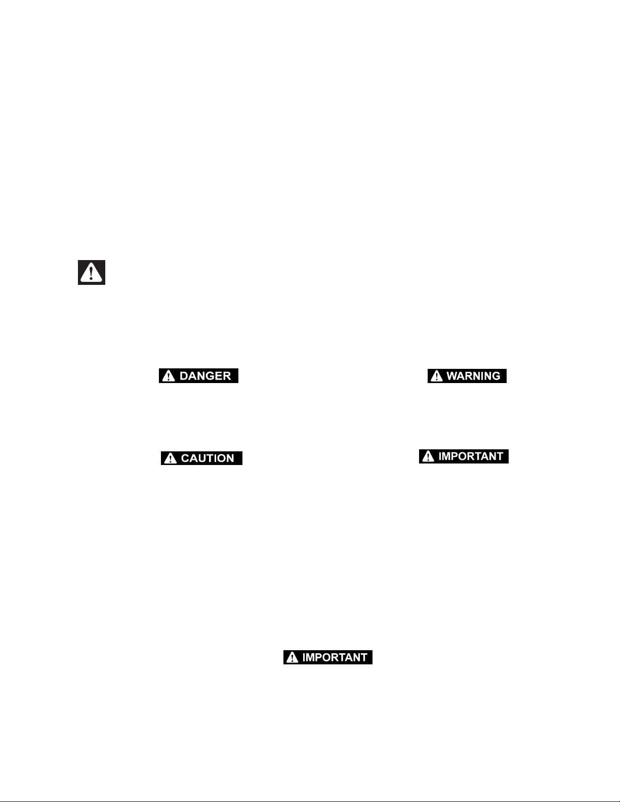
THIS "SAFETY ALERT SYMBOL" IS USED TO CALL ATTENTION TO POTENTIAL HAZARDS
WHICH MAY LEAD TO SERIOUS INJURY OR DEATH IF IGN ORED.
Safety of personnel and proper use of the machine are of primary concern, DANGER, WARNING, CAUTION,
IMPORTANT, INSTRUCTIONS and NOTE are i nserted throughout this manual to emphasize these areas.
They are defined as follows:
DANGER INDICATES AN IMMINENTLY HAZARDOUS SITUATION WHICH, IF NOT AVOIDED WILL RESULT IN SERIOUS
INJURY OR DEATH.
CAUTION INDICATES A POTENTIALLY HAZA RDOUS SITUATION WHICH, IF NOT AVOID E D, MAY RESULT IN MINOR OR
MODERATE INJURY. IT MAY ALSO BE USED TO ALERT
AGAINST UNSAFE PRACTICES.
Also in this Manual "Notes:" are used to provide information of special intere st.
JLG INDUSTRIES, INC. MAY HAVE ISSUED SAFETY RELATED BULLETINS FOR YOUR JLG PRODUCT. CONTACT JLG INDUSTRIES, INC. OR THE LOCAL AUTHORIZED JLG DISTRIBUTOR FOR INFORMATION CONCERNING SAFETY RELATED BULLETINS WHICH MAY HAVE BEEN ISSUED FOR YOUR JLG PRODUCT. ALL ITEMS REQUIRED BY THE SAFETY RELATED
BULLETINS MUST BE COMPLETED ON THE AFFECTED JLG PRODUCT.
WARNING INDICATES A POTENTIALLY HAZARDOUS SITUATION WHICH, IF NOT AVOIDED COULD RESULT IN SERIOUS INJURY OR DEATH.
IMPORTANT OR INSTRUCTIONS PROCEDURES ESSENTIAL
FOR SAFE OPERATION AND WHICH, IF NOT FOLLOWED
MAY RESULT IN A MALFUNCTION OR DAMAGE TO THE
MACHINE.
Due to the continuous product improvements, JLG Industries, Inc. reserves the right to make specification changes without
prior notification. Contact JLG Industries, Inc. for updated information.
Page 4

This page intentionally left blank.
Page 5

INTRODUCTION - OPERATION/SAFETY PRECAUTIONS
INTRODUCTION - OPERATION/SAFETY PRECAUTIONS
All procedures herein are based on the use of t he
machine under pro per op era ting con ditio ns, w ith no de viations from original design intent ... as per OSHA regulations.
READ & HEED!
The ownership, use, service, and/or maintenance of this
machine is subject to various federal, state and local laws
and regulations. It is the responsibility of the owner/user to
be knowledgeable of these laws and regulations and to
comply with them. The most prevalent regulations of this
type are the Federal OSHA Safety Regulations*. Listed
below, in abbreviated form are some of the requirements
of Federal OSHA regulations in effect as of the date of
publication of this hand book.
The listing of these requirements shall not relieve the
owner/user of the responsibility and obligation to determine all applicable laws and regulations and their exact
wording and requirements, and to comply with the
requirements. Nor shall the listing of these requirements
constitute an assumption of responsibility of liability on the
part of JLG Industries, Inc.
1. Only trained and authorized operators shall be permitted to operate the aerial lift.
2. A malfunctioning lift shall be shut down until
repaired.
3. The controls shall be plainly marked as to their function.
4. The controls shall be tested each day prior to use to
determine that they are in safe operating condition.
5. Load l imits specified by t he manufacturer sha ll not
be exceeded.
6. Instruction and warning placards must be legible.
7. Aerial lifts may be "field modified" for uses other than
those intended by the manufacturer only if certified
in writing by the manufacturer or an equivalent
entity, such as a nationally recognized testing lab, to
be in conformity to applicable OSHA safety regulations and to be at least as safe as it was prior to
modification.
8. Aerial lifts shall not be used near electric power lines
unless the lines have been deenergized or adequate
clearance is maintained (see OSHA 29 CFR 1910.67
and 1926.400).
9. Employees using aerial lifts shall be instructed how
to recognize and avoid unsafe conditions and hazards.
10. Ground controls shall not be operated unless permission has been obtained from personnel in the
platform, except in case of an emergency.
11. Regular inspection of the job site and aerial lift shall
be performed by competent persons.
12. Personnel shall always stand on the floor of the platform, not on boxes, planks, railing or other devices
for work posit ioning.
*Applicable Federal OSHA regulations, as of the date of
publication of this manual include, but are not limited to,
29 CFR 1910.67, 29 CFR 1926.20, 29 CFR 1926.21, 29
CFR 1926.28, 29 CFR 192 6.400 and 29 CFR 1926.453.
Consult the current regulations for the exact wording and
full text of the requirements and contact the closest Federal OSHA office for specific interpretations.
3120727 – JLG Lift – a
Page 6
INTRODUCTION - MAINTENANCE SAFETY PRECAUTIONS
INTRODUCTION - MAINTENANCE SAFETY PRECAUTIONS
A. GENERAL
This section contains the general safety precautions
which must be observed during maintenance of the aerial
platform. It is of utmost importance that maintenance personnel pay strict attention to these warnings and precautions to avoid possible injury to themselves or others or
damage to the equipment. A maintenance program must
be established by a qualified person and must be followed
to ensure that the machine is safe to operate.
MODIFICATION OF THE MACHINE WITHOUT CERTIFICATION BY
A RESPONSIBLE AUTHORITY THAT THE MACHINE IS AT LEAST
AS SAFE AS ORIGINALLY MANUFACTURED IS A SAFETY VIOLATION.
The specific precautions to be observed du ring machine
maintenance are inserted at the appropriate point in the
manual. These precautions are, for the most part, those
that apply when servicing hydraulic and larger machine
component parts.
Your safety, and that of others, is the first consideration
when engaging in the maintenance of equipment. Always
be conscious of component weight and never attempt to
move heavy parts without the aid of a mechanical device.
Do not allow heavy objects to rest in an unstable position.
When raising a portion of the equipment, ensure that adequate support is provided.
SINCE THE MACHINE MANUFACTURER HAS NO DIRECT CONTROL OVER THE FIELD INSPECTION AND MAINTENANC E,
SAFETY IN THIS AREA IS THE RESPONSIBILITY OF THE OWNER/
OPERATOR.
C. MAINTENANCE
FAILURE TO COMPLY WITH SAFETY PRECAUTIONS LISTED IN
THIS SECTION COULD RESULT IN MACHINE DAMAGE, PERSONNEL INJURY OR DEATH AND IS A SAFETY VIOLATION.
• REMOVE ALL RINGS, WATCHES, AND JEWELRY
WHEN PERFORMING ANY MAINTENANCE.
• DO NOT WEAR LONG HAIR UNRESTRAINED, OR
LOOSE FITTING CLOTHING AND NECKTIES WHICH
ARE APT TO BECOME CAUGHT ON OR ENTANGLED
IN EQUIPMENT.
• OBSERVE AND OBEY ALL DANGER, WARNING, CAUTION AND OTHER INSTRUCTIONS ON MACHINE
AND IN SERVICE MANUAL.
• KEEP STANDING SURFACES AND HAND HOLDS
FREE OF OIL, GREASE, WATER, ETC.
• NEVER WORK UNDER AN ELEVATED PLATFORM
UNTIL PLATFORM HAS BEEN SAFELY RESTRAINED
FROM ANY MOVEMENT BY BLOCKING OR OVERHEAD SLING.
• BEFORE MAKING ADJUSTMENTS, LUBRICATING OR
PERFORMING ANY OTHER MAINTENANCE, SHUT
OFF ALL POWER CONTROLS.
• BATTERY SHOULD ALWAYS BE DISCONNECTED
DURING REPLACE MENT OF ELEC TRICAL CO MPONENTS.
• KEEP ALL SUPPORT EQUIPMENT AND ATTACHMENTS STOWED IN THEIR PROPER PLACE.
• USE ONLY APP ROVED, NONFLAMMABLE CLEANING
SOLVENTS.
B. HYDRAULIC SYSTEM SAFETY
1. It should be particularly noted that the machines
hydraulic systems operate at extremely high and
potentially dangerous pressures. Every effort should
be made to relieve any system pressure prior to disconnecting or removing any portion of the system.
2. Relieve system pressure by activating the lift DOWN
control with the platform completely lowered to
direct any line pressure back into the return line to
the reservoir. Pressure feed lines to system components can then be disconnected with minimal fluid
loss.
b – JLG Lift – 3120727
Page 7

EFFECTIVITY PAGE
EFFECTIVITY CHANGES
September 15, 1997 - Date of Issue
January 20, 2000 - Revised
February 7, 2000 - Revised - Section-2, Page 2-5, (removed lube check requirement for drive wheel gear box).
March 22, 2000 – Revised – Added 20VP UL-EE Option.
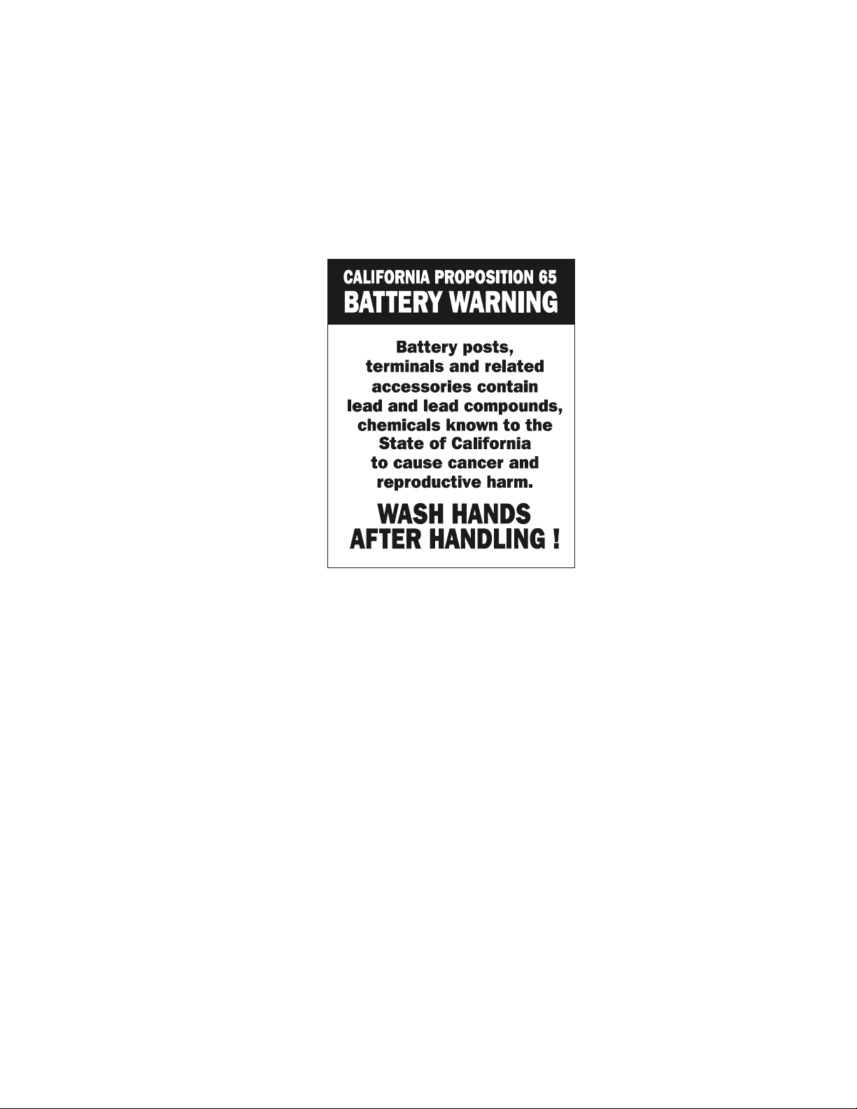
April 20, 2000 – Revised – Added Proposition 65 to front of manual.
3120727 – JLG Lift – c
Page 8

EFFECTIVITY PAGE
This page intentionally left blank.
d – JLG Lift – 3120727
Page 9

TABLE OF CONTENTS
SUBJECT - SECTION, PARAGRAPH PAGE NO.
SECTION INTRODUCTION - - MAINTENANCE SAFETY PRECAUTIONS
A General . . . . . . . . . . . . . . . . . . . . . . . . . . . . . . . . . . . . . . . . . . . . . . . . . . . . . . . . . . . . . . . . . . . . . .b
B Hydraulic System Safety. . . . . . . . . . . . . . . . . . . . . . . . . . . . . . . . . . . . . . . . . . . . . . . . . . . . . . . . .b
C Maintenance . . . . . . . . . . . . . . . . . . . . . . . . . . . . . . . . . . . . . . . . . . . . . . . . . . . . . . . . . . . . . . . . . .b
SECTION 1 - SAFETY PRECAUTIO NS
1.1 General . . . . . . . . . . . . . . . . . . . . . . . . . . . . . . . . . . . . . . . . . . . . . . . . . . . . . . . . . . . . . . . . . . . . . .1-1
1.2 Electrocution Hazard. . . . . . . . . . . . . . . . . . . . . . . . . . . . . . . . . . . . . . . . . . . . . . . . . . . . . . . . . . . .1-1
1.3 Transporting Machine. . . . . . . . . . . . . . . . . . . . . . . . . . . . . . . . . . . . . . . . . . . . . . . . . . . . . . . . . . .1-1
1.4 Pre-operational Safety. . . . . . . . . . . . . . . . . . . . . . . . . . . . . . . . . . . . . . . . . . . . . . . . . . . . . . . . . . .1-2
1.5 Operating Safety . . . . . . . . . . . . . . . . . . . . . . . . . . . . . . . . . . . . . . . . . . . . . . . . . . . . . . . . . . . . . . .1-3
SECTION 2 - PREPARATION AND INSPEC TI ON
2.1 General . . . . . . . . . . . . . . . . . . . . . . . . . . . . . . . . . . . . . . . . . . . . . . . . . . . . . . . . . . . . . . . . . . . . . .2-1
2.2 Preparation For Use . . . . . . . . . . . . . . . . . . . . . . . . . . . . . . . . . . . . . . . . . . . . . . . . . . . . . . . . . . . .2-1
2.3 Delivery And Frequent Inspection. . . . . . . . . . . . . . . . . . . . . . . . . . . . . . . . . . . . . . . . . . . . . . . . . .2-1
2.4 Daily Walk-around Inspection. . . . . . . . . . . . . . . . . . . . . . . . . . . . . . . . . . . . . . . . . . . . . . . . . . . . .2-2
2.5 Daily Functional Check. . . . . . . . . . . . . . . . . . . . . . . . . . . . . . . . . . . . . . . . . . . . . . . . . . . . . . . . . .2-3
2.6 Torque Requirements . . . . . . . . . . . . . . . . . . . . . . . . . . . . . . . . . . . . . . . . . . . . . . . . . . . . . . . . . . .2-4
2.7 Battery Charging & Maintenance . . . . . . . . . . . . . . . . . . . . . . . . . . . . . . . . . . . . . . . . . . . . . . . . . .2-5
SECTION 3 - USER RESPONSIBILITIES & MACHINE CONTROLS
3.1 General . . . . . . . . . . . . . . . . . . . . . . . . . . . . . . . . . . . . . . . . . . . . . . . . . . . . . . . . . . . . . . . . . . . . . .3-1
3.2 Personnel Training . . . . . . . . . . . . . . . . . . . . . . . . . . . . . . . . . . . . . . . . . . . . . . . . . . . . . . . . . . . . .3-1
3.3 Operating Characteristics And Limitations . . . . . . . . . . . . . . . . . . . . . . . . . . . . . . . . . . . . . . . . . . .3-2
3.4 Controls And Indicators. . . . . . . . . . . . . . . . . . . . . . . . . . . . . . . . . . . . . . . . . . . . . . . . . . . . . . . . . .3-2
3.5 Jlg Pot-Hole Protection Device. . . . . . . . . . . . . . . . . . . . . . . . . . . . . . . . . . . . . . . . . . . . . . . . . . . . 3-5
SECTION 4 - MACHINE OPERATION
4.1 Machine Description . . . . . . . . . . . . . . . . . . . . . . . . . . . . . . . . . . . . . . . . . . . . . . . . . . . . . . . . . . . .4-1
4.2 General . . . . . . . . . . . . . . . . . . . . . . . . . . . . . . . . . . . . . . . . . . . . . . . . . . . . . . . . . . . . . . . . . . . . . .4-1
4.3 Machine Operation . . . . . . . . . . . . . . . . . . . . . . . . . . . . . . . . . . . . . . . . . . . . . . . . . . . . . . . . . . . . .4-2
4.4 Quick-change Platform . . . . . . . . . . . . . . . . . . . . . . . . . . . . . . . . . . . . . . . . . . . . . . . . . . . . . . . . . .4-4
4.5 Transporting, Lifting And Tie Down Procedures. . . . . . . . . . . . . . . . . . . . . . . . . . . . . . . . . . . . . . .4-5
SECTION 5 - OPTIONAL EQUIPMEN T
5.1 Optional Equipment . . . . . . . . . . . . . . . . . . . . . . . . . . . . . . . . . . . . . . . . . . . . . . . . . . . . . . . . . . . .5-1
5.2 Extendible Platform Operation . . . . . . . . . . . . . . . . . . . . . . . . . . . . . . . . . . . . . . . . . . . . . . . . . . . .5-2
SECTION 6 - EMERGENCY PROCEDURES
6.1 General Information. . . . . . . . . . . . . . . . . . . . . . . . . . . . . . . . . . . . . . . . . . . . . . . . . . . . . . . . . . . . . 6-1
6.2 Emergency Controls And Their Location . . . . . . . . . . . . . . . . . . . . . . . . . . . . . . . . . . . . . . . . . . . .6-1
6.3 Emergency Operation. . . . . . . . . . . . . . . . . . . . . . . . . . . . . . . . . . . . . . . . . . . . . . . . . . . . . . . . . . .6-1
6.4 Incident Notification. . . . . . . . . . . . . . . . . . . . . . . . . . . . . . . . . . . . . . . . . . . . . . . . . . . . . . . . . . . . . 6-2
SECTION 7 - INSPECTION AND REPAIR LOG
3120727 – JLG Lift – i
Page 10

TABLE OF CONTENTS
(Continued)
LIST OF FIGURES
FIGURE NO. TITLE PAGE NO.
2-1. Daily Walk-Around Inspection. . . . . . . . . . . . . . . . . . . . . . . . . . . . . . . . . . . . . . . . . . . . . . . . . . . . .2-3
2-2. Battery Fluid Level. . . . . . . . . . . . . . . . . . . . . . . . . . . . . . . . . . . . . . . . . . . . . . . . . . . . . . . . . . . . . .2-5
2-3. Charge r Assembly and Power Cor d St or age. . . . . . . . . . . . . . . . . . . . . . . . . . . . . . . . . . . . . . . . .2-5
2-4. Battery Charger Front Panel. . . . . . . . . . . . . . . . . . . . . . . . . . . . . . . . . . . . . . . . . . . . . . . . . . . . . .2-6
2-5. Lubrication Chart. . . . . . . . . . . . . . . . . . . . . . . . . . . . . . . . . . . . . . . . . . . . . . . . . . . . . . . . . . . . . . .2-7
2-6. Torque Chart. . . . . . . . . . . . . . . . . . . . . . . . . . . . . . . . . . . . . . . . . . . . . . . . . . . . . . . . . . . . . . . . . .2-8
3-1. Ground Controls.. . . . . . . . . . . . . . . . . . . . . . . . . . . . . . . . . . . . . . . . . . . . . . . . . . . . . . . . . . . . . . .3-3
3-2. Platform Controller. (OLD STYLE). . . . . . . . . . . . . . . . . . . . . . . . . . . . . . . . . . . . . . . . . . . . . . . . . . 3-3
3-3. Platform Controller. (NEW STYLE). . . . . . . . . . . . . . . . . . . . . . . . . . . . . . . . . . . . . . . . . . . . . . . . .3-4
3-4. Brake Re l ease Handle. . . . . . . . . . . . . . . . . . . . . . . . . . . . . . . . . . . . . . . . . . . . . . . . . . . . . . . . . . .3-5
3-5. JLGs Pot-Hole-Protecti on Device - PHP Bar Operation. . . . . . . . . . . . . . . . . . . . . . . . . . . . . . . . .3-5
3-6. Decal Locations (Front View) . . . . . . . . . . . . . . . . . . . . . . . . . . . . . . . . . . . . . . . . . . . . . . . . . . . . .3-6
3-7. Decal Locations (Rear View). . . . . . . . . . . . . . . . . . . . . . . . . . . . . . . . . . . . . . . . . . . . . . . . . . . . . .3-7
3-8. Decal Locations (Top View) . . . . . . . . . . . . . . . . . . . . . . . . . . . . . . . . . . . . . . . . . . . . . . . . . . . . . .3-8
3-9. Decal Locations (Right/Left View). . . . . . . . . . . . . . . . . . . . . . . . . . . . . . . . . . . . . . . . . . . . . . . . . . 3 -9
3-10. Wheel Load Decals (10/15/20VP). . . . . . . . . . . . . . . . . . . . . . . . . . . . . . . . . . . . . . . . . . . . . . . . . .3-10
4-1. Quick-Change Platform Mount. . . . . . . . . . . . . . . . . . . . . . . . . . . . . . . . . . . . . . . . . . . . . . . . . . . .4-4
4-2. Forklift Truck Lifting Pockets and Machine Tie Down Bar Locations. . . . . . . . . . . . . . . . . . . . . . . 4-5
5-1. Extendible Platform. (Platform shown extended) . . . . . . . . . . . . . . . . . . . . . . . . . . . . . . . . . . . . . .5-2
LIST OF TABLES
TABLE NO. TITLE PAGE NO.
1-1 Minimum Safe Approach Dista n c e (to e ne r gized power lines or parts) . . . . . . . . . . . . . . . . . . . .1-1
2-1 Lubrication Interval s for Various Components . . . . . . . . . . . . . . . . . . . . . . . . . . . . . . . . . . . . . . . .2-7
4-1 Maximum Rated Load Capaci t y (for all platforms ex ce pt E xtendible) . . . . . . . . . . . . . . . . . . . . . .4-2
4-2 Maximum Rated Load Capaci t y (for Extendible Pla t form*) . . . . . . . . . . . . . . . . . . . . . . . . . . . . . .4-2
4-3 Machine Interlock Swi t ch Operating Conditions. . . . . . . . . . . . . . . . . . . . . . . . . . . . . . . . . . . . . . .4-2
4-4 Machine Gross Weights . . . . . . . . . . . . . . . . . . . . . . . . . . . . . . . . . . . . . . . . . . . . . . . . . . . . . . . . .4-6
7-1 Inspection and Repair Log . . . . . . . . . . . . . . . . . . . . . . . . . . . . . . . . . . . . . . . . . . . . . . . . . . . . . . .7-1
ii – JLG Lift – 3120727
Page 11
SECTION 1 - SAFETY PRECAUTIONS
SECTION 1. SAFETY PRE CAUTIONS
1.1 GENERAL
This section prescribes the prope r and safe practices for
major areas of machine usage which have been divided
into three basic categories: Transporting, Pre-Operation
and Operation. In order to promote proper usage of the
machine, it is mandatory that a daily routine be established based on instruction given in this section. A maintenance program must also be established by a qual ified
person and must be followed to ensure that the mach ine
is safe to operate.
The user/operator of the machine should not accept operating responsibility until this manual has been READ and
UNDERSTOOD, and operating instructions of the
machine under the supervision of an experienced and
qualified operator, has been completed. If there is a q uestion on application and/or operation, JLG Industries Product Safety and Reliability personnel should be consulted.
MODIFICATION OF THE MACHINE WITHOUT APPROVAL OF JLG
INDUSTRIES, OR CERTIFICATION BY A NATIONALLY RECOGNIZED TESTING LAB TO BE IN CONFORMITY WITH APPLICABLE
OSHA REGULATIONS AND ANSI STANDARDS, AND TO BE AT
LEAST AS SAFE AS BEFORE MODIFICATION, IS PROHIBITED,
AND IS A VIOLATION OF OSHA RULES.
1.2 ELECTROCUTION HAZARD
Minimum safe approach distances (M.S.A.D.) to energized (exposed or insulated) power lines and parts.
DO NOT MANEUVER MACHINE OR PERSONNEL TO DISTANCE
LESS THAN M.S.A.D (SEE TABLE 1-1.). ASSUME ALL ELECTRICAL PARTS AND WIRING ARE ENERGIZED UNLESS KNOWN
OTHERWISE.
THIS MACHINE DOES NOT PROVIDE PROTECTION FROM CONTACT WITH OR PROXIMITY TO AN ELECTRICALLY CHARGED
CONDUCTOR. MAINTAIN A CLEARANCE OF AT LEAST 10 FT.
(3M) BETWEEN ANY PART OF THE MACHINE AND ANY ELECTRICAL LINE OR APPARATUS CARRYING UP TO 50,000 VOLTS. 1
FT. (0.3M) ADDITIONAL CLEARANCE IS REQUIRED FOR EVERY
ADDITIONAL 30,000 VOLTS OR LESS. ALLOW FOR PLATFORM
SWAY, ROCK OR SAG AND ELECTRICAL LINE SWAYING, (SEE
FOLLOWING TABLE).
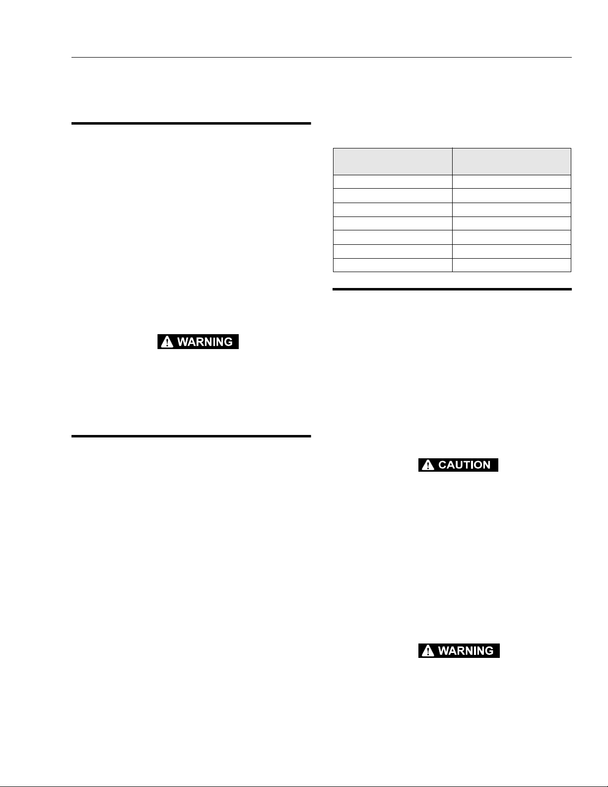
Table 1-1. Minim um Safe Appr oach Distance
(to energized power lines or parts)
VOLTAGE RANGE
(PHASE TO PHASE)
0-300V Avoid Contact
Over 300V to 50KV 10 ft. [3 m]
Over 50KV to 200KV 15 ft. [4.6 m]
Over 200KV to 350KV 20 ft. [6 m]
Over 350KV to 500KV 25 ft. [7.6 m]
Over 500KV to 750KV 35 ft. [10.6 m]
Over 750KV to 1000KV 45 ft. [13.7 m]
MINIMUM SAFE DISTANCE -
Feet [m]
1.3 TRANSPORTING MACHINE
Before transporting (haulin g ) the machine the user/ operator must be familiar with the proper procedures for transporting the machine (see Section 4-5), as well as the
weight and size of the machine.
The user/operator should be familiar with the surrounding
work area and surface before transporting the machine.
The work area must be a firm surface capable of supporting the combined weight of the trans port vehicl e and the
machine.
NOTE: Remember that the key to safe and proper usage is
common sense and its careful application.
ALWAYS RELEASE THE DRIVE MOTOR BRAKES ON THE
MACHINE WHEN MANUALLY PUSHING, PULLING, OR WHEN
TRANSPORTING MACHINE BY FORK-LIFT TRUCK. THIS WILL
ALLOW THE REAR DRIVE WHEELS, GEAR BOX DRIVE SHAFT
AND GEARS TO ROTATE FREELY PREVENTING ANY DAMAGE
TO THE DRIVE SYSTEM.
IF MACHINE IS PLACED ON A TRANSPORT VEHICLE, REENGAGE THE BRAKES IN COMBINATION WITH PROPER
MACHINE TIE DOWN, TO RESTRAIN MACHINE FROM ANY MOVEMENT DURING TRANSPORT.
ALWAYS REMEMBER TO RE-ENGAGE THE BRAKE SYSTEM
BEFORE OPERATING MACHINE.
.
FAILURE TO COMPLY WITH SAFETY PRECAUTIONS LISTED IN
THIS SECTION AND ON MACHINE COULD RESULT IN MACHINE
DAMAGE, PERSONAL INJURY OR DEATH AND IS A SAFETY VIOLATION.
3120727 – JLG Lift – 1-1
Page 12
SECTION 1 - SAFETY PRECAUTIONS
LIFT MACHINE AT DESIGNATED
LIFTING POINTS ONLY
1.4 PRE-OPERATIONAL SAFETY
• READ YOUR MANUAL. UNDERSTAND WHAT YOU’VE
READ - THEN BEGIN OPERATIONS.
• ALLOW ONLY THOSE AUTHORIZED AND QUALIFIED
PERSONNEL TO OPERATE MACHINE WHO HAVE
DEMONSTRATED THAT THEY UNDERSTAND SAFE
AND PROPER OPERATION AND MAINTENANCE OF
THE UNIT.
•AN OPERATOR MUST NOT ACCEPT OPERATING
RESPONSIBILITIES UNTIL ADEQUATE TRAINING HAS
BEEN GIVEN BY COMPETENT AND AUTHORIZED
PERSONS.
•BEFORE OPERATION CHECK WORK AREA FOR
OVERHEAD ELECTRIC LINES. (SEE ELECTROCUTION
HAZARD, SECTION 1-2.)
• STUDY THE WORK AREA FOR AREAS TO AVOID
SUCH AS; SURFACE EDGES THAT DROP-OFF,
HOLES OR DIPS IN SURFACE, OR ANY UNLEVEL
AREAS WHICH COULD CAUSE THE UNIT TO TIP
OVER.
•ALSO BEFORE OPERATION CHECK WORK AREA FOR
MACHINE TRAFFIC SUCH AS FORKLIFTS, CRANES,
AND OTHER CONSTRUCTION EQUIPMENT.
• ENSURE THAT OPERATORS OF OTHER OVERHEAD
AND FLOOR LEVEL MACHINES ARE AWARE OF THE
AERIAL PLATFORMS PRESENCE. DISCONNECT
POWER TO OVERHEAD CRANES. BARRICADE FLOOR
AREA IF NECESSARY.
• PRECAUTIONS TO AVOID ALL KNOWN HAZARDS IN
THE WORK AREA MUST BE TAKEN BY THE OPERATOR AND HIS SUPERVISOR BEFORE STARTING THE
WORK.
• DO NOT OPERATE THIS MACHINE UNLESS IT HAS
BEEN SERVICED AND MAINTAINED ACCORDING TO
THE MANUFACTURERS SPECIFICATIONS AND
SCHEDULE.
•ENSURE DAILY INSPECTION AND FUNCTION CHECK
IS PERFORMED PRIOR TO PLACING MACHINE INTO
OPERATION. HAVE AUTHORIZED PERSONNEL TAKE
ANY NECESSARY CORRECTIVE ACTION BEFORE
PLACING MACHINE INTO OPERATION.
• NEVER DISABLE OR MODIFY ANY SAFETY DEVICE.
ANY MODIFICATION OF THE MACHINE IS A SAFETY
VIOLATION AND IS A VIOLATION OF OSHA AND ANSI
RULES.
• DO NOT OPERATE MACHINE WHEN EXPOSED TO
HIGH WIND, RAIN OR SNOW.
•NEVER OPERATE OR RAISE PLATFORM WHEN
MACHINE IS ON A TRUCK OR OTHER VEHICLE.
• APPROVED HEAD GEAR (I.E. HARD HAT, ETC.) MUST
BE WORN WHEN REQUIRED BY ALL OPERATING AND
GROUND PERSONNEL.
•READ AND OBEY ALL DANGER, WARNINGS, CAUTIONS AND OPERATING INSTRUCTIONS ON
MACHINE AND IN THIS MANUAL.
• BE FAMILIAR WITH LOCATION AND OPERATION OF
GROUND CONTROLS AND EMERGENCY CONTROLS.
1-2 – JLG Lift – 3120727
Page 13
SECTION 1 - SAFETY PRECAUTIONS
•NEVER POSITION THE UNIT SIDEWAYS ON A SLOPE.
• USE CAUTION AND CHECK CLEARANCES WHEN
MOVING MACHINE IN RESTRICTED OR CLOSE
QUARTERS.
• ALWAYS USE AN ASSISTANT WHEN MOVING
MACHINE IN AREAS WHERE VISION IS
OBSTRUCTED.
General Operating Safety
•KEEP NON-OPERATING PERSONNEL AT LEAST 6
FEET (1.8 M) AWAY FROM MACHINE DURING OPERATIONS.
• DO NOT OPERATE ANY MACHINE ON WHICH DANGER, WARNING, CAUTION OR INSTRUCTION PLACARDS OR DECALS ARE MISSING OR ILLEGIBLE.
•NEVER EXCEED MANUFACTURERS RATED PLATFORM CAPACITY - REFER TO CAPACITY DECAL ON
MACHINE.
•NEVER OPERATE A MALFUNCTIONING MACHINE. IF
A MALFUNCTION OCCURS, SHUT DOWN THE
MACHINE, RED TAG IT, AND NOTIFY PROPER
AUTHORITIES.
ALWAYS LOOK IN DIR ECTION OF TRAVE L
1.5 OPERATING SAFETY
FAILURE TO OBSERVE THE FOLLOWING TIPPING HAZARD
INSTRUCTIONS COULD CAUSE THE UNIT TO TIP OVER OR BE
HARD TO CONTROL WHEN BEING MOVED, WHICH COULD
RESULT IN SERIOUS INJURY OR DEATH DUE TO BEING PINNED
OR CRUSHED BY THE UNIT.
Driving Safety
• READ YOUR MANUAL, UNDERSTAND WHAT YOU’VE
READ - THEN BEGIN OPERATIONS.
•WATCH FOR OBSTRUCTIONS AROUND MACHINE
AND OVERHEAD WHEN MOVING.
•CHECK TRAVEL PATH FOR PERSONS, HOLES,
BUMPS, DROP-OFFS, OBS TRUCTIONS, DEBRIS, AND
COVERINGS WHICH MAY CONCEAL HOLES AND
OTHER HAZARDS, AS TIPPING COULD OCCUR.
•BEFORE MOVING MACHINE ON FLOORS AND OTHER
SURFACES, CHECK AL LOWABLE CAPACITY OF SURFAC ES .
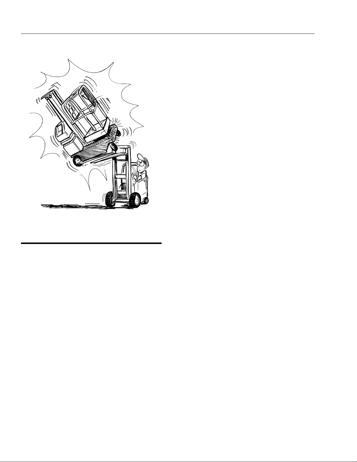
•DO NOT OPERATE MACHINE ON SOFT FOOTING
THAT WILL ALLOW THE WHEELS TO SETTLE INTO OR
BREAK THROUGH SURFACE, AS TIPPING WILL
OCCUR.
NEVER OPERATE ON SOFT
OR UNEVEN SURFACES
3120727 – JLG Lift – 1-3
Page 14
SECTION 1 - SAFETY PRECAUTIONS
ALWAYS STAND ON PLATFORM FLOOR
NOT ON BOXES, PLANKS OR RAILINGS
• ALL PERSONNEL MUST STAND CLEAR WHEN PLATFORM IS BEING RAISED OR LOWERED. BE SURE TO
WATCH FOR OVERHEAD AND OTHER OBSTRUCTIONS.
• CHECK CLEARANCES A BOVE, ON SIDES AND BOTTOM OF PLATFORM WHEN RAISING AND LOWERING
PLATFORM.
• NEVER USE THE MAST TO GAIN ACCESS TO OR
LEAVE PLATFORM.
•DO NOT ATTACH OVERHANGING LOADS TO THE
PLATFORM OR INC REA SE THE PLATFORM S IZ E WI TH
UNAUTHORIZED DECK EXTENSIONS OR ATTACHMENTS.
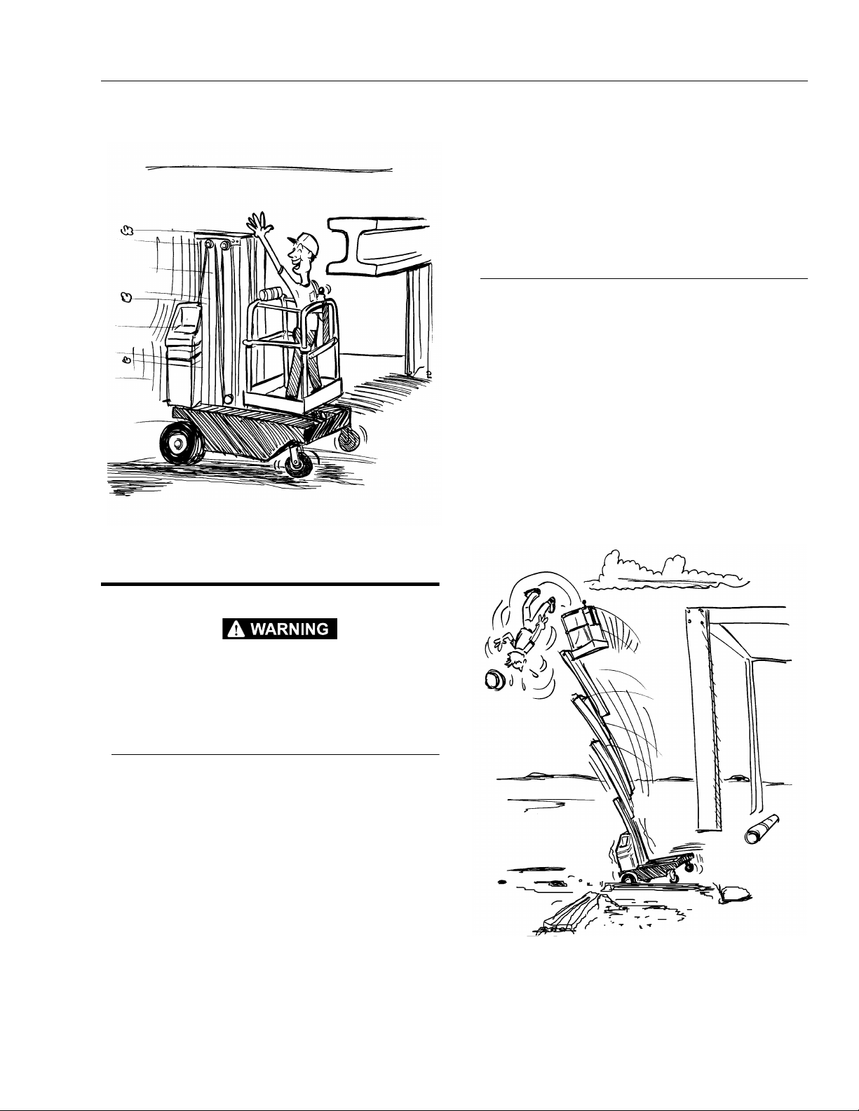
•DO NOT TIE OFF MACHINE TO ANY ADJACENT
STRUCTURE. NEVER ATTACH WIRE, CABLE OR ANY
SIMILAR ITEMS TO PLATFORM.
•TRANSFERS BETWEEN A STRUCTURE AND THE
AERIAL PLATFORM EXPOSE OPERATING PERSONNEL TO FALL POTENTIALS. THIS PRACTICE SHOULD
BE DISCOURAGED WHEREVER POSSIBLE. WHERE
TRANSFER MUST BE ACCO MPLISHED TO PERFO RM
THE JOB, AN APPROVED FALL PROTECTION DEVICE
AND TWO SAFETY LANYARDS WILL BE USED. ONE
LANYARD SHOULD BE ATTACHED TO THE AERIAL
PLATFORM. THE OTHER TO THE STRUCTURE. THE
SAFETY LANYARD THAT IS ATTACHED TO THE
KEEP EVERYONE CLEAR OF A
WORKING PLATFORM
AERIAL PLATFORM SHOULD NOT BE DISCONNECTED UNTIL SUCH TIME AS THE TRANSFER TO
THE STRUCTURE IS COMPLETE. WHEN RE-ENTERING THE PLATFORM THIS PROCEDURE MUST BE
PERFORMED IN REVERSE. TO AVOID FALLING - USE
EXTREME CAUTION WHEN ENTERING OR LEAVING
PLATFORM ABOVE GROUND. ENTER OR EXIT THRU
GATE ONLY. PLATFORM FLOOR MUST BE WITHIN 1
FOOT (0.3 M) OF ADJACENT - SAF E AND SECURE STRUCTURE. ALLOW FOR ANY VERTICAL MOVEMENT OF PLATFORM (UP OR DOWN) WHEN ENTERING OR LEAVING PLATFORM.
• NO HORSEPLAY IS PERMITTED IN PLATFORM.
•DO NOT ALLOW PERSONNEL TO TAMPER WITH,
SERVICE, OR OPERATE THIS MACHINE FROM THE
GROUND WITH PERSONNEL I N PLATFORM EXCEPT
IN AN EMERGENCY.
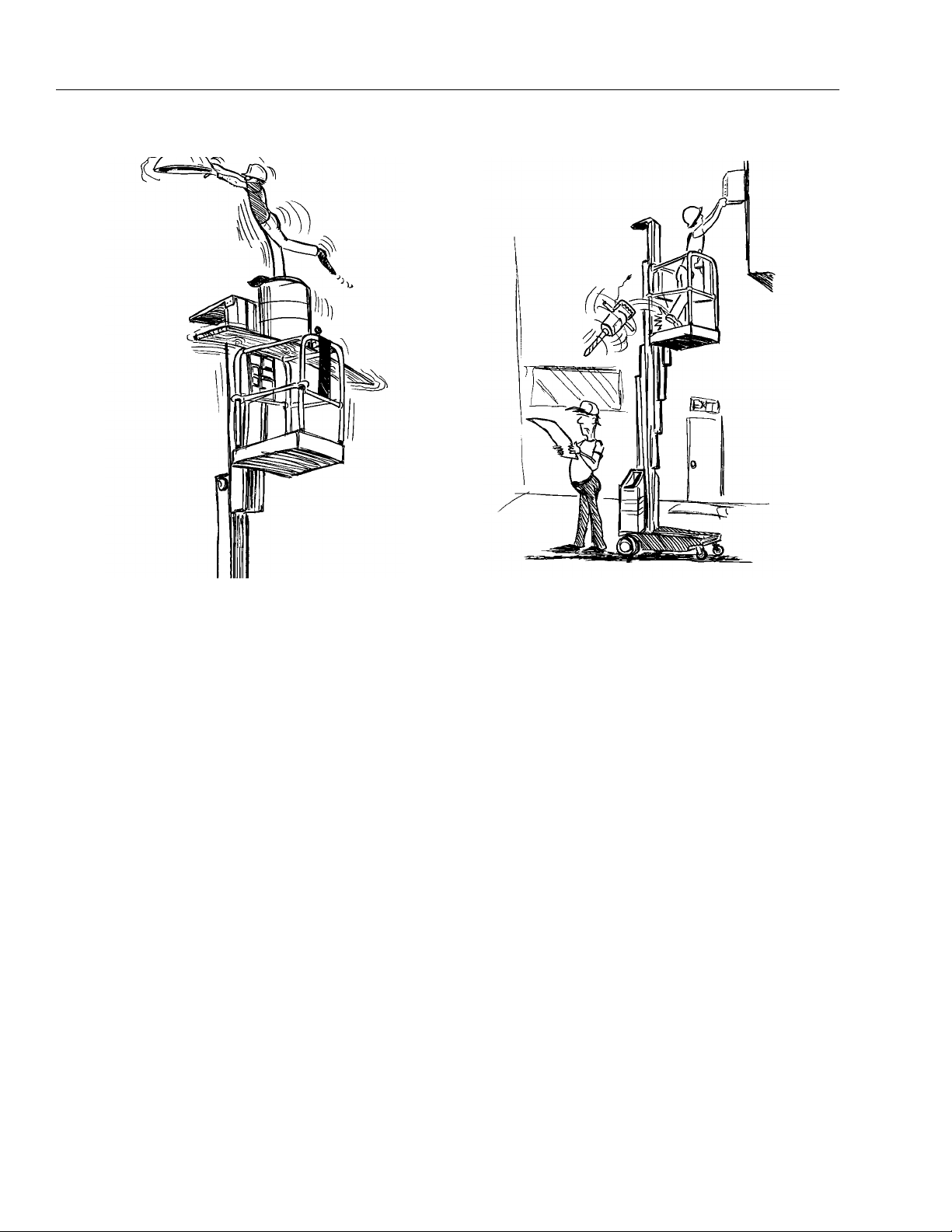
• DURING OPERATION KEEP ALL BODY PARTS INSIDE
PLATFORM RAILINGS.
•NEVER POSITION LADDERS, STEPS, OR SIMILAR
ITEMS ON UNIT TO PROVIDE ADDITIONAL REACH
FOR ANY PURPOSE.
1-4 – JLG Lift – 3120727
Page 15
SECTION 2 - PREPARATION AND IN SPECTION
SECTION 2. PREPARATION AND INSPECTION
2.1 GENERAL
This section provides the necessary information needed
by those personnel that are responsible to place the
machine in operation readiness, and lists checks that are
performed prior to use of the machine. It is important that
the information contained in this section be read and
understood before any attempt is made to operate the
machine. Ensure that all the necessary inspections have
been completed successfully before placing the machine
into service. These procedures will aid in obtainin g maximum service life and safe operation.
SINCE THE MACHINE MANUFACTURER HAS NO DIRECT CONTROL OVER THE FIELD INSPECTION AND MAINTENANCE, THIS
IS THE RESPONSIBILITY OF THE OW NER/OPERATOR.
2.2 PREPARATION FOR USE
Before a new machine is put into operation it must be
carefully inspecte d for any e vidence of damage resulting
from shipment and inspected pe riodically thereafter, as
outlined in Section 2-3, Delivery and Frequent Inspection.
The unit should be thoroughly checked for hydraulic leaks
during initial start-up and run. A check of all components
should be made to assure their security.
All preparation n ecessar y to pl ace the machin e in oper ation readiness status are the responsibility of management personnel. Preparation requires good common
sense, (i.e. lift works smoothly) coupled with a series of
visual inspections. The mandatory requirements are given
in Section 2-4, Daily Walk Around Inspection.
It should be assured that the items appearing in the Delivery and Frequent Inspection and Functional Check are
complied with prior to putting the machine into service.
2.3 DELIVERY AND FREQUENT INSPECTION
The following check list provides a systematic inspec tion
to assist in detecting defective, damaged, or improperly
installed parts. The check list denotes the items to be
inspected and conditions to examine. Frequ ent in spectio n
shall be performed every three (3) months or 150 hours,
or more often when required by environment, severit y,
and frequency of usage.
Platform Assembly
Properly secured; no visible damage; free of dirt and
debris. Platform gate functions properly.
Mast
No visible damage, abrasions and/or distortions; no binding; mast sections fr ee of dirt or othe r foreign mate rial.
Sequenci ng ca bles pro perl y se cure d; n o vis ibl e dam age;
proper cable tension.
Mast Chains & Cables
No visible damage; proper chain/cable tension; evidence
of proper lubrication. Chain/cable sheaves, sheave pins
and rollers properly secured; no visible damage.
Platform Controller/(Power) Cable(s)
No visible damage; cable properly tensioned and seated
in control cable sheaves; control cable sheave s not damaged and rotating freely.
Lift Cylinder (check w/mast extended)
No rust, nicks, scratches or foreign material on piston rod.
No leakage.
Frame
No visible damage; loose or missing hardware (top and
underside).
Drive Wheels and Front Casters
Casters free rolling; no loose or missing parts; no visible
damage. Drive wheel hub retain er ring secure; no damage
to wheel tread; electric drive motors secure; no loose or
missing wires.
Hydraulic Oil Supply
Check the hydraulic oil level of the hydraulic fluid reservoir
located in the l ower ac cess hol e on the rear c over. Main-
tain an oil level to the “Fill To Line” indicator on the side of
reservoir.
If fluid level is low, see Table 2-1. “Lubrication In terval
Chart” for information on hydraulic oil.
3120727 – JLG Lift – 2-1
Page 16
SECTION 2 - PREPARAT ION AND INSPECTION
Controls - (Platform and Ground)
Controls operable; no visib le damage; placar ds secure
and legible.
Batteries
Proper electrolyte level; cable connections tight; no visible
damage; no corrosion at battery cabl e con nections.
Pump Motor/Hydraulic Pump/Valves
andLines
No leakage; units secure.
Placards
No visible damage; placards secure and legible.
2.4 DAILY WALK-AROUND INSPECTION
It is the user/operator’s responsibility to inspect the
machine before the start of each work day. It is recommended that each user/operator inspect the machine
before operation, even if the machine has already been
put into service under another user/operator. This Daily
Walk-Arou nd Inspection is the preferred method of inspection.
4. Motor/Pump/Reservoir Unit - Properly secured, no
visible damage, no evidence of hydraulic leaks.
Hydraulic oil level should be filled level with the full
line, (“Fill To Line”) on the side of t he hy drauli c rese r-
voir. Also check that reservoir cap is properly
secured.
5. Ground Controls - Properly secured, no loose or
missing parts, no visible damage; key switch operable, no visible damage; placards secure and legible;
emergency stop switch, no visible damage and
properly set for operation.
6. Mast Assembly - Mast sections properly secured,
no visible damage to mast sections, no loose or
missing parts, slide pads properly secured. Mast
chains/cables properly secured and lubricated.
Sequencing cables properly secured and undamaged. Platform control and power cables (on side of
mast), no visible damage; cables properly tensioned
and seated in sheaves; cab le sh eaves n ot damaged
and rotating freely . Elevation/Speed Limit switch (top
inside of mast sectio n 1) secure and working properly.
7. Manual Brake Release Control - Handle secure
and undamaged; cables attached properly; control
in working orde r.
General
Begin the “Walk-Around Inspection” at item one listed following. Continue ar ound machi ne check ing each item in
sequence for the conditions listed in the “Walk-Around
Inspection Check list”.
TO AV OID INJURY DO NOT OPERATE MACHINE UNTIL ALL MALFUNCTIONS HAVE BEEN CORRECTED. USE OF A MALFUNCTIONING MACHINE IS A SAFETY VIOLATION.
TO AVOID POSSIBLE INJURY, BE SURE MACHINE POWER IS
“OFF” DURING “WALK-AROUND INSPECTION”.
NOTE: Do not overlook visual inspection of the base frame
underside. Check this area for objects or debris
which could cause extensive machine damage.
1. Drive and Caster Wheels - Properly secured and
lubricated. Check for any visible damage or debris,
stuck to or around wheels.
2. Base Frame - No visible damage; drive wheel motor
components properly secured; JL G’s Pot-Hole-Protection System components secure; no loose wires
or cables dangling below the base; bubble level in
place and functioning properly.
3. Battery/Battery Charger - Proper battery electrolyte
level, cables secure, no damage or corrosion.
8. Platform Assembly - Secure to mast; All railings
securely attached; no loose or missing parts, no visible damage; sliding entry bar in proper working
order. Platform gate working properly, no visible sign
of damage (if so equipped).
9. Platform Controls - Platform up/down, function
enable and horn buttons on faceplate no loose or
missing parts, no visible damage. Joystick control
secure. Placards secure and legible, emergency
shut-off button set for operation. Control markings
legible; Operators manual enclosed in manual storage box.
In addition to the Daily W alk-Around Inspection, be sure to
include the following as part of the daily inspection:
Batteries Charged
Start each day with fully charged batteries. (See Section 2-
7. “Battery Charging & Maintenance”)
Overall Cleanliness
Keep oil, grease, water, etc. wiped from standing surfaces
and hand holds.
Placards
Keep all information and operating placards clean and
unobstructed. Cover areas where placards are present
when using the machine for spraying paint or any materi al
which could cover these surfaces and reduce legibility.
2-2 – JLG Lift – 3120727
Page 17

SECTION 2 - PREPARATION AND IN SPECTION
6
Daily Walk-Around
Inspection Items
7
9
3
8
4
5
1. Drive and Castor Wheels
2. Base Frame
3. Battery/Battery Charger
4. Motor/Pump/Rese rvoir Unit
5. Ground Controls
6. Mast Assembly
7. Manual Brake ReleaseControl
8. Platform Assembly
9. Platform Controls
1
2
Figure 2-1. Daily Walk-Around Inspection.
Operation and Safety and ANSI
Responsibilities Manual
Ensure a copy of manua l is enclo sed in t he manual storage box.
Lubrication
For those parts pointed out in the Walk-Around Inspection
requiring lubrication, refer to the Lubricat ion Chart, Table
2-1., for specific time interval requirements.
Hydraulic oils must have anti-wear qualities at least to API
Service Classification GL-3, and sufficient chemical stability for mobile hydraulic system service. JLG Industries,
recommends Mobilfluid 424 h ydraulic oil, which h as an
SAE viscosity of 10W-30 and a viscosity index of 152.
For cold weather applications, i.e. when temperature s
remain consistently below +20°F (–7°C) JLG recommends using Mobil DTE 13 hydraulic oil.
1
2.5 DAILY FUNCTIONAL CHECK
TO AVOID INJURY DO NOT OPERATE A MACHINE UNTIL ALL
MALFUNCTIONS HAVE BEEN CORRECTED. USE OF A MALFUNCTIONING MACHINE IS A SAFETY VIOLATION.
Once the Walk-Around Inspection is complete, a Functional Check of all systems should be performed in an
area free of overhead and ground level obstructions. Perform a Functional Check in accordance with the following
procedures:
Set-up machine for o pera tio n, a ccor di ng t o i ns tr uct ions in
Section 4-3, “Machine Oper ation”.
NOTE: 20VP MODELS WITH UNDERWRITERS LABORA-
TORY (EE) RATING OPTION ONLY, include a mas-
ter ON/OFF switch l ocated on top of the rear co ve r of
the machine. This control must be set to the ON
position before the following function checks can be
completed.
3120727 – JLG Lift – 2-3
Page 18

SECTION 2 - PREPARAT ION AND INSPECTION
SEE SECTION-3 F OR SPECIFIC IN FORMATION ABOUT OPE RATING MACHINE CONTROLS AND SEC TION-4 FOR OPERATION O F
MACHINE.
5. While driving the machine forward rotate the SPEED
CONTROL knob from maximum to minimum (clockwise to counterclockwise) checking for proper operation. If operating properly, s peed should vary from
2 mph to 1/2 mph.
Ground Controls Function Check
1. With key switch turned to GRND position (clock-
wise), operate the platform up and down switch
(located in lower access hole with hydraulic fluid reservoir). Raise and lower platform 2 ft. to 3 ft. (.5m to
1m) several times. Check for smooth elevation and
lowering of platform.
2. With platf orm completely lowered, check hydraulic
oil level in hydraulic fluid reservoir. If necessary, add
hydraulic fluid to proper level (full line). NEVER USE
HYDRAULIC BRAKE FLUID, refer to the Lubrication
Chart (Table 2-1.) for specific requirements.
3. Depress EMERGENCY STOP (red) button (next to
key switch), all machine operations will be disabled
if functioning properly. If ok, reset EMERGENCY
STOP for operation.
4. Operate the MANUAL BRAKE RELEASE CONTROL
(Over-center handle mounted on the right side of the
mast). When the handle is in the vertical pos ition it is
set for norm al operation, brak es ENGAGED. When
the handle is pulled DOWN to a horizontal position,
the brakes are DISENGAGED.
5. Set key switch to PLAT (platform operation, all the
way counterclockwise) and continue with the follow-
ing steps.
Platform Controls
NOTE: Check that the MANUAL BRAKE RELEASE CON-
TROL (Over-center handle mounted on side of
mast), is set for normal operation (brakes engaged)
before entering platform.
1. Check that the PLATFORM CONTROL box is properly mounted (facing forward) and secure on the
platform’s rail.
2. On the PLATFORM CONTROL box, check the BATTERY STATUS INDICATOR LED’s for charge status
of batteries.
3. Check for proper operation of the FUNCTION
ENABLE pad, and that the JOYSTICK CONTROL
moves freely.
4. Activate the JOYSTICK and slowly move it in all
directions, if operating properly the machine will
move in the direction the JOYSTICK is pointed.
NOTE: A short delay between lift motor start and platform
movement is normal.
6. Activate the platform UP and DOWN buttons (up
arrow and down arrow) to raise and lower platform 2
ft. to 3 ft. (.5m to 1m) several times. Check for
smooth elevation and lowering of platform.
7. With the platform elevated check the JLG Automatic
Pot-Hole-Protection system, if operating properly,
the PHP bars on each side of the machine b ase will
be automatically engaged (lowered) with the plat-
form raised approximately 2 ft.
8. With the platform still elevated approximately 2 ft.,
drive machine and check if SPEED CUT-BACK is
operating properly, machine should drive at 1/4 of
speed when platform was completely lowered.
9. Depress the EMERGENCY STOP (red) button on the
Platform Control box, all machine operations will be
disabled if functioning properly. RESET the EMERGENCY STOP.
Tilt Sensor (1.5°) and Drive Brakes
1. With the platform lowered, drive the machine onto a
grade withi n the al lowab le grade and s lope lim its of
the machine (maximum grade of 15% or 8.5°, maxi-
mum side slope of 5°). St op the machine part of the
way up the grade, check if the drive brakes hold the
machine in place. Also while on the grade (of greater
than 1.5°), attempt to raise the platform. The tilt sensor (1.5°) must prevent the platform from elevating
and will sound a beeping alarm at the platform controller box.
If all machine functions are operating properly, machine is
ready for operation.
2.6 TORQUE REQUIREMENTS
The Torque Chart, Figure 2-5., consists of standard torque
values based on bolt diameter and grade, it also specifies
dry and wet torque values in accordance with recommended shop practices. This chart is provided as an aid
to the user/operator in the event he/she notices a condition that requires prompt attention during the walk-around
inspection or during operation unti l the pro per service personnel can be notified. Utilizing this Torque Chart in conjunction with the Preventive Maintenance and Inspection
Schedule table in the Service Manual, will enhance the
safety, reliability, and performance of the machine.
2-4 – JLG Lift – 3120727
Page 19

SECTION 2 - PREPARATION AND IN SPECTION
SWITCH
BATTERY
CHARGER
2.7 BATTERY CHARGING & MAINTENANCE
VP Models are equipped with 24 volt, 10 amp output battery chargers (U.S.A. - 120 Volt AC input/60Hz and Brazil -
220 Volt AC input/60 Hz). The battery charg er includ es a
microprocessor controll ed automatic charge sen sing circuit which can determine cell voltage and regulate
charger output as required. The charger automatically terminates charging whe n a full battery charge is achei ved.
Also a built-in interlock device prohibi ts driving the
machine while the battery charger is plugged in.
Battery Maintenance an d Safety Practices
(Refer to Figure 2-2.)
ENSURE THAT BATTERY ACID DOES NOT COME INTO CONTACT
WITH SKIN OR CLOTHING. WEAR PROTECTIVE CLOTHING AND
EYEWEAR WHEN WORKING WITH BATTERIES. NEUTRALIZE ANY
BATTERY ACID SPILLS WITH BAKING SODA AND WATER.
BATTERY ACID RELEASES AN EXPLOSIVE GAS WHILE CHARGING, ALLOW NO OPEN FLAMES, SPARKS OR LIGHTED TOBACCO
PRODUCTS IN THE AREA WHILE CHARGING BATTERIES.
CHARGE BATTERIES ONLY IN A WELL VENTILATED AREA.
ADD ONLY DISTILLED WATER TO BATTERIES. WHEN ADDING
DISTILLED WATER TO THE BATTERIES, A NON-METALLIC CONTAINER AND/OR FUNNEL MUST BE USED.
BATTERY
FILLER CAP
1/8 "
PLATES
Figure 2-2. Battery Fluid Level.
CORD
STORAGE
AREA
VENT TUBE
FLUID LEVEL OF FULLY
CHARGED BATTERY
KEY
As with any wet cell batt ery, check the electrolyte le vel of
the batteries often, adding only distilled water when
required. When fully charged, battery fluid level should be
1/8" below vent tubes. (See Figure 2-2.).
•DO NOT fill to bottom of vent tubes.
• DO NOT allow fluid level to go below the top of the
plates when charging or operating.
Figure 2-3. Charger Assem b ly and
Power Cord Storage.
Battery Charger Operation
(Refer to Figure 2-3 & 2-4.)
1. Position machine in well ventilated area near an AC
electrical outlet and set the Ground Control-PLAT/
OFF/GRND key switch to the OFF position.
2. Open the left battery cover and unwrap the battery
charger AC power cable from under the co v e r.
3120727 – JLG Lift – 2-5
Page 20

SECTION 2 - PREPARAT ION AND INSPECTION
3. Connect the battery charger AC power cable to a
properly grounded receptacle, use a suitable extension cord, if necessary.
4. When powered on, the charger runs through a selfdiagnostic check which lights all five (5) lights o n the
face of the charger three (3) times, then each light in
sequence, then all five (5) lights three (3) times
again on the front panel of the battery charger.
5. When ready to charge, the CHARGER ON light and
the INCOMPLETE light on the front panel of the
charger will light up, the charger will then begin to
charge the batteries.
NOTE: If the ABNORMAL CYCLE light comes on and stays
on at any time during the charge cycle, see sub-section following about the ABNORMAL CYCLE indicator light.
6. When the battery cell voltage reaches 2.37 V/cell the
80% CHARGE light on the front panel of the charger
will light up. The charger then continues to monitor
the increase in charge until it sees no increase, and
then terminates the charging process.
7. The CHARGE COMPLETE light will come on when
the charging process is finished.
8. Unplug the charger AC power cord and wrap
around storage lugs under the left battery cover.
Figure 2-4. Battery Charger Fr ont Panel.
Abnormal Cycle Indicator Light
If the ABNORMAL CYCLE indicator light should come on
during the normal charging cycle of the batteries, it could
indicate any of the following conditions;
• The AC input to the charger was interupted, i.e. local
power failure or ch arger cable was un plugged or
bumped and power was interupted intermittently.
•A dead cell or cells in either battery would prevent the
charger from sensing enough voltage to complete the
battery charge.
•One or more of the batteries terminal connections loose
resulting in an intermittent incomplete circuit.
2-6 – JLG Lift – 3120727
Page 21

SECTION 2 - PREPARATION AND IN SPECTION
6
1
2
3
4, 5
Figure 2-5. Lubrication Chart.
Table 2-1.Lubrication Intervals for Various Components
INTERVAL HOURS
ITEM COMPONTENT
1 Hydraulic Oil Fill T o Line on
2 Drive Wheel
Bearings
3 Drive Wheel
Gear Box
NO/TYPE
LUBE POINTS
LUBE/METHOD
HO - Check Hyd. Oil
Reservoir
5 Qt. Reservoir
Level
HO - Change Hyd. Oil
4 - Grease Fittings MPG- Pressure Gun
2 - Gear Box Gear Oil
4 Caster Axles 2 - Grease Fitting MPG - Pressure Gun
5 Swivel Raceways 2 - Front Casters MPG - Pressure Gun
6 Mast Chains * 2 - Per Section Chain Lube - Brush or
Spray
3
MONTHS
150 Hrs.
✔
✔
✔
✔
6
MONTHS
300 Hrs.
1
YEAR
600 Hrs.
2
YEARS
1200 Hrs.
✔
COMMENTS
Check hydraulic oil every 10 hrs.
Change hydraulic oil every 1200
hrs.
Change only when serviced -
requires 175cc’s to fill.
Inspect, lubricate if dry or rusting.
* Applies Only to Mast Sections with Chains .
Key to Lubricants: MPG - Multipurpose Grease
HO - Hydraulic Oil - Hydraulic oils must have anti-wear qualities at least to API Service Classification GL-3, and sufficient
chemical stability for mobile hydraulic system service. JLG Ind ustries, recommends Mobilfluid 424
hydraulic oil, which has an SAE viscosity of 10W-30 and a viscosity index of 152.
For cold weather applications, i.e. when temper atures remain consi stently below +20°F ( –7°C) JLG
recommends using Mobil DTE 13 hydraulic oil.
Notes: 1. Be certain to lubricate like items on each side of the machine.
2. Recommended lubricating intervals are based on normal use. If machine is subjected to severe operating conditions,
such as a high number of cycles, location, corrosive/dirty environment, etc., user must adjust lubricating requirements accordingly .
3. Prior to checking hydraulic oil level, operate machine through one complete cycle of lift function (full up and down). Failure to do so will
result in incorrect oil level reading on the hydraulic reservoir .
3120727 – JLG Lift – 2-7
Page 22

SECTION 2 - PREPARAT ION AND INSPECTION
Figure 2-6. Torque Chart.
2-8 – JLG Lift – 3120727
Page 23

SECTION 3 - USER RESPONSIBILITIES & MACHINE CONTROLS
SECTION 3. USER RESPONSIBILITIES & MACHINE CONTROLS
3.1 GENERAL
SINCE THE MANUFACTURER HAS NO DIRECT CONTROL OVER
MACHINE APPLICATION AND OPERATION, CONFORMANCE WITH
GOOD SAFETY PRACTICES IN THESE AREAS IS THE RESPONSIBILITY OF THE USER AND HIS OPERATING PERSONNEL.
This section provides the necessary information needed
to understand control functions. Included in this section
are the operating characteris tic s and limitations, and functions and purposes of controls and indicators. It is important that the user/operator read and understand the
proper procedures before operati ng the machine. T hese
procedures will aid in obtaining optimum ser vice lif e and
safe operation.
3.2 PERSONNEL TRAINING
The aerial lift is a personnel handling device; therefore, it
is essential that it be operated and maintained only by
authorized personnel who have demonstrated that they
understand the proper use and maintenance of the
machine. It is important that all personnel who are
assigned to and responsible for the operation and ma in te nance of the machine undergo a thorough training program and check out period in order to become familiar
with the characteristics prior to operating the machine.
In addition, personnel operati ng the machine should be
familiar with Sections - 6, 7, 8, 9, & 10 - " Responsibili ties"
of the ANSI standard A92.6. This standard contains sections outlining the responsibilities of the owners, users,
operators, lessors and lessees concerning safety, training,
inspection, maintenance, application and operation. The
standard is included with the literature package shipped
with the machine.
Persons under the influence of drugs or alcohol or who
are subject to seizures, dizziness or loss of physical control must not be permitted to operate the machine.
Operator Training
Operator training must include instruction in the following:
1. Use and limitations of the platform controls, ground
controls and emergency controls.
2. Knowledge and unders t anding of this manu al and of
the control markings, instructions and warnings on
the machine itself.
3. Knowledge and understanding of all safety work
rules of the employer and Federal, State and Local
Statutes, including training in the recognition and
avoidance of potential hazards in the work place;
with particular attention to the work to be performed.
4. Proper use of all required personnel safety equipment.
5. Sufficient knowledge of the mechanical operation of
the machine to recognize a malfunction or potential
malfunction.
6. The safest means to operate near overhead obst ructions, other moving equipment, obstacles, depressions, holes, drop-offs, etc. on the supporting
surface.
7. Means to avoid the hazards o f unprotected e le ctrical
conductors.
8. Any other requirements of a specific job or machine
application.
Training Supervision
Training must be do ne under the supervision of a qualified
operator or supervisor in an open area free of obstructions
until the trainee has developed the ability to safely control
an aerial lift in congested work locations.
Operator Responsibility
The operator must be instructed that he has the responsibility and authority to shut down the machine in case of a
malfunction or other unsafe condition of either the
machine or the job site and to request further information
from his supervisor or JLG Distributor before proceeding.
NOTE: Manufacturer or Di st r i but or w il l pr ovi de qu al i fie d pe r -
sons for training assistance with first machine(s)
delivered and thereafter as requested by user or his
personnel .
3120751 – JLG Lift – 3-1
Page 24

SECTION 3 - USER RESPONSIBILITIES & MACHINE CONTROLS
3.3 OPERATING CHARACTERISTICS AND
LIMITATIONS
General
A thorough knowledge of the operating characteristics
and limitations of the machine is always the first require-
ment for any user, regardless of user’s experience with
similar types of equipment.
Placards
(See Figures 3-6, 3-7, 3-8 & 3-9.)
Important points to remember during operation are pro-
vided at the control stations by DANGER, WARNING,
CAUTION, IMPORTANT and INSTRUCTION placards. This
information is placed at various locations on the machine
for the express purpose of alerting personnel of potential
hazards constituted by the operating characteristics and
load limitations of the machine. See the Foreword at the
start of this manual for a definition of the seriousness of
each of the above placard types. See decal location figures in this section for decals which apply to this machine.
Capacities
Raising the platform above the stowed position is based
on the following criteria:
• The machine is positioned on a smooth, firm level surface.
• The load is within manufacturer’s rated capacity.
• All machine systems are functioning properly.
3.4 CONTROLS AND INDICATORS
Ground Controls
(See Figure 3-1.)
NOTE: When the mac hi ne is no t be in g us ed or w h en ch arg -
ing the battery, be sure the POWER PLAT/OFF/
GRND KEY SWITCH is positioned to OFF to prevent
draining the batteries. For information on battery
charging see SECTION 2-7, Battery Charging.
1. MASTER ON/OFF SWITCH
(20VP UL-EE OPTION ONLY)
A master ON/OFF switch is included on 20VP
machines with the UL - EE option. The master switch
is located on top of the rear cover on the left side of
the machine. When set to OFF all power is disconnected from the batteries to the machine. When set
to ON all power is restored.
2. POWER PLAT/OFF/GROUND KEY SWITCH
A key operated power PLAT/OFF/GROUND switch
located in the upper access hole of the rear cover
(on back of machine), controls power to all functions
on the machine. The machine platform controls will
not operate without the key inserted and turned to
the PLAT (platform) position. When the key switch is
set to the GRND (ground) position this allows use of
the platform UP/DOWN switch located next to the
hydraulic oil reservoir (lower access hole). When left
unattended, removing the key will prevent unauthorized machine use.
Stability
This machine, as originally manufactured by JLG and
when operated withi n its rated capaci ty on a smooth , fir m
and level supporting surface (check bubble level i ndic a tor
on base frame), provides a stable aerial platform for all
platform positions.
3. PLATFORM UP/DOWN (GROUND CO NTROL)
The ground operated platform control switch is
located next to the hydraulic reservoir in the lower
access hole of the rear cover. This three position
toggle switch will raise (lift up) and lower (lift down),
the platform from the ground control position when
the PLAT/OFF/GRND key switch is set to the GRND
(ground) position.
4. EMERGENCY STOP BUTTON
An EMERGE NCY STOP (red button) is mo unted on
both the ground control station and the platform
control. When either button is depressed, all
machine functions wi ll stop. To re-activate powe r to
the machine, turn button 1/4 turn to RESET the
emergency stop switch.
5. EMERGENCY/MANUAL DESCENT KNOB
This (RED knurled) knob, located on the electric/
hydraulic pump-motor unit in the lower access hole
of the rear co ver provides for lowering of the pla tform in the event of an emergency or power failure.
Turn knob (counterclockwise) to open the valve and
3-2 – JLG Lift – 3120751
Page 25

SECTION 3 - USER RESPONSIBILITIES & MACHINE CONTROLS
Figure 3-1. Ground Controls.
lower the platform. This valve must be closed
(turned all the wa y clockwise) for normal operation
of the machine. (Refer to Section 6 for Emergency
Descent operating procedures.)
6. HYDRAULIC OIL RESERVOIR
The hydraulic oil reservoir is housed inside the lower
access hole in the rear cover. Check the hydraulic oil
level visually by observing the oil level in the reservoir as compared to the FILL TO LINE indicator on
the side of the reservoir. Hydraulic oil can be added
if necessary through the OIL FILL CAP on top of the
reservoir. DO NOT OVERFILL.
NOTE: Always check hydraulic oi l level with oil at operati ng
temperature and with the platform completely lowered.
7. ELECTRICAL CIRCUIT BREAKER PANEL & FUSE
(20VP w/UL-EE OPTION ONLY)
20VP machines with the UL-EE option include a cir-
cuit breaker panel with five push button type reset
circuit breakers, (two-5 amp and three -1 amp). The
two (5 amp) breakers add protection on the pump
valve and key switch circuits. The three (1 amp)
breakers add protection to the motion alarm, tilt
alarm, and optional beacon circuits. Also an 80 amp
fuse is mounted near the breaker panel for added
protection on the pump motor circuit. These items
are located under the rear cover on top of the mast
support bracket.
Platform Controller
(See Figure 3-2. & 3-3.)
The platform controller contains all the controls necessary
to operate the lift from the platform.
The following is a description of each function.
1. BATTERY VOLTAGE/FAULT CODE LED INDICATORS.
The LED strip (green when lit) running between the
pad buttons on the controller pad indicates the battery voltage level when the machine is powered-up.
The graduated LED strip indicates batteries at FULL
CHARGE (25 volts) when lit all the way to the top (F),
and a LOW CHARGE (18 volts) at bottom (E) when
one or two LEDs are illuminated.
NOTE: When voltage drops below 16.5 volts an error code
is indicated, and the batteries will require a recharge .
This LED strip also acts as a fault code indicator to
help diagnose problems with the machines’ electrical system. (See Service Manual Troubleshooting,
for information about reading fault codes).
2. FUNCTION ENABLE SWITCH
This switch must be pressed before any of the platform or joystick drive functions can be operated.
Once activated, the operator has approximately
three seconds to activate any of the control functions.
(OLD STYLE) (Fig. 3 - 2 )
3120751 – JLG Lift – 3-3
Page 26

SECTION 3 - USER RESPONSIBILITIES & MACHINE CONTROLS
2. LIFT ENABLE SWITCH (NEW STYLE) (Fig. 3-3.)
The LIFT ENABLE switch must be pressed and
HELD before UP/DOWN LIFT of the platform is operational.
3. PLATFORM UP SWITCH (Up Arrow)
When pressed and HELD (in conjunction with the
enable pad switch) this switch raises the platform to
a higher level, when released the upward mo vem e nt
is stopped.
4. PLATFORM DOWN SWITCH (Down Arrow)
When pressed and HELD (in conjunction with the
enable pad switch) this switch lowers the platform
from a raised position, when released, the downward movement is stopped.
5. EMERGENCY STOP/SHUT-OFF BUTTON
An EMERGENCY STOP (RED) button is provided in
order to immediately stop machine functions from
the platform in the event of an emergency. When
button is depressed, all machine functions will stop.
To re-activate power to the machine, turn button
Figure 3-2. Platform Controll er. (OLD STYLE)
clockwise to RESET the emergency stop.
6. JOYSTICK DRIVE/STEER CONTROL
(OLD STYLE)
This is a “Point & Go™” control which moves the
platform in the direction which the stick is moved. It
is a fully proportional control, the further from the
center position the joystick is moved, the faster the
machine travels. To activate the control depress the
FUNCTION ENABLE pad switch and within three (3)
seconds, move the joystick in the direction desired.
7. JOYSTICK DRIVE/STEER CONTROL and DRIVE
ENABLE BUTTON
(NEW STYLE)
This is a “Point & Go™” control which moves the
machine in the direction which the stick is moved. It
is a fully proportional control, the further from the
center position the joystick is moved, the faster the
machine travels. To activate the control PRESS and
HOLD the DRIVE ENABLE BUTTON on the top of
the joystick and move the joystick in the direction
desired.
8. VARIABLE SPEED CONTROL
The variable speed control knob can be used to
increase or decrease the maximum drive speed of
the machine. Clockwise rotation increases speed,
counterclockwise decreases speed.
When platform the elevated more than 2 ft. (approx.)
Figure 3-3. Platform Controller. (NEW STYLE)
drive speed is automatically cut to 1/4 the speed
from when the platform was completely lowered.
3-4 – JLG Lift – 3120751
Page 27

SECTION 3 - USER RESPONSIBILITIES & MACHINE CONTROLS
9. WARNING HORN PAD
If machine is equipped with (optional) mounted
horn, this pad when pressed sounds the horn.
Brake Release Control
(See Figure 3-4.)
Standard equipment on all VP Series lifts is a braking system integrated into the electric motor drive system. The
braking system is spring engaged and released electrically while the machine is being driven with the joystick
controller. When the lift is at rest or the power is turned off,
the brakes are automatically engaged.
If the lift must be moved around manually as a result of
the batteries become depleted and the machine needs to
be moved from an aisleway, or machine is being winched
onto a roll-back truck bed, etc. To release the brakes, a
brake release control has been provided to engage/disengage the brake system.
Figure 3-4. Brake Release Handle.
FOLLOW ALL APPLICABLE SAFETY PRECAUTIONS WHEN MANUALLY MOVING MACHINE AROUND (SEE SECTION 1-3).
WHEN PUSHED OR PULLED MANUALLY, THE MACHINE‘S
BRAKES MUST BE DISENGAGED AND THE EMERGENCY STOP
BUTTON SET TO THE OFF POSITION, (DEPRESSED). DO NOT
ATTEMPT TO TOW OR WINCH THE MACHINE AT A SPEED
GREATER THAN (2) MPH, OR DAMAGE COULD OCCUR TO THE
MACHINE‘S ELECTRONIC CONTR OLLER BOX. (DUE TO HIGH
VOLTAGE BEING GENERATED BY THE DRIVE MOTORS FEEDING
BACK INTO THE CONTROLLER BOX).
The brake release control lever is located on the right side
of the mast (bubble level side). To disengage or engage
the brakes, check the brake decal located just above the
handle assembly to see which direction the handle needs
to be pointed, (the brakes are ENGAGED (normal driving
position) when the handle is in the up (vertical) position,
and DISENGAGED (machine can be moved manually
when the handle is pulled down in a horizontal position).
When brakes are disengaged the machine can then be
moved around manually.
AFTER THE MACHINE HAS BEEN MANUALLY MOVED AND
BEFORE DRI VING M ACHI NE, ALWAYS RE-ENG AGE T HE BRA KE
SYSTEM.
3120751 – JLG Lift – 3-5
Page 28

SECTION 3 - USER RESPONSIBILITIES & MACHINE CONTROLS
3.5 JLG POT-HOLE PROTECTION DEVICE
(See Figure 3-5.)
All VP Series lifts are equipped with JLGs Pot-Hole-Protection system (PHP). The PHP system consists of hinged
PHP bars extending from the bottom edge of both sides of
the base frame, as well as actuating cables and limit
switch assemblies, the PHP bars are actuated by an
assembly mounted at the base of the mast. The PHP bars
are automatically ENGAGED (lowered) when the platform
is raised more than (approximately) six (6") inches. The
bars have a ground clearance of approximately three
quarters (3/4") inch when ENGAGED (lowered), and are
designed to support the weight of the machine should
one of its wheels drop into a hole or crack. As the machine
drops onto the PHP bar, the bar will limit the amount of tilt
the machine will incur and reduce the likelihood of the
machine tippin g over. If this condition should occur, the
operator must then fully lower the platform, exit the platform, and safely remove the machine from the situation.
When the machine is driven in areas where obstacles are
higher than three quarters (3/4") inch off the work surface
(door sills, thick carpeting, etc.) the platform must be com pletely lowered to allow the PHP bars to DISENGAGE
(retract), allowing sufficient clearance of the machine’s
base frame.
Figure 3-5. JLGs Pot-H ole-Protection Device -
PHP Bar Operation.
3-6 – JLG Lift – 3120751
Page 29

SECTION 3 - USER RESPONSIBILITIES & MACHINE CONTROLS
Figure 3-6. Decal Locations (Front View)
3120751 – JLG Lift – 3-7
Page 30

SECTION 3 - USER RESPONSIBILITIES & MACHINE CONTROLS
Figure 3-7. Decal Locations (Rear View)
3-8 – JLG Lift – 3120751
Page 31

SECTION 3 - USER RESPONSIBILITIES & MACHINE CONTROLS
Figure 3-8. Decal Locations (Top View)
3120751 – JLG Lift – 3-9
Page 32

SECTION 3 - USER RESPONSIBILITIES & MACHINE CONTROLS
BRAKE HANDLE MUST
BE IN “FREE-WHEELING“
POSITION & GROUND
STATION KEY
SWITCH MUST BE
IN “OFF” POSITION
BEFORE TOWING OR
WINCHING MACHINE
TOW OR WINCH
SLOWLY:
2 MPH MAX.
1703708
P/N-1703708
BRAKE
FREE
WHEELING
1703636
P/N-1703636
BATTERY INFORMATION
AMP HR (20 HR RATE)
VOLTAGE
BATTERY
DIMENSIONS
3252331
P/N-3252311
(20VP UL-EE OPTION)
BATTERY INFORMATION
AMP HR (20 HR RATE)
VOLTAGE
BATTERY
DIMENSIONS
3252331
P/N-1703072
Figure 3-9. Decal Locations (Right/Left View)
3-10 – JLG Lift – 3120751
Page 33

SECTION 3 - USER RESPONSIBILITIES & MACHINE CONTROLS
1140 lbs
MAX
640 lbs
289 kg
P/N-1704498
MAX
853 lbs
386 kg
10VP
1703501
15VP
1703502
P/N-1704499
MAX
20VP
516 kg
1703503
P/N-1704500
Figure 3-10. Wheel Load Decals (10/15/20VP)
3120751 – JLG Lift – 3-11
Page 34

SECTION 3 - USER RESPONSIBILITIES & MACHINE CONTROLS
This page intentionally left blank.
3-12 – JLG Lift – 3120751
Page 35

SECTION 4 - MACHINE OPERATION
SECTION 4. MACHINE OPERATION
4.1 MACHINE DESCRIPTION
The JLG VP Series model line of lifts are an electric selfpropelled machine, with an aerial work platform mounted
to an elevating aluminum mast mechanism. The mast is
raised and lowered by a hydraulic cylinder extending
between mast section-1 and -2, the remaining mast sections are proportionally extended and retracted using
steel chains or cables. Hydraulic pressure is supplied to
the lift cylinder by an electrically po wered hydraulic pump.
All VP Series models feature a steel base frame with swivel
caster wheels mounted on the front and fixed drive wheels
on the rear of the machine. The personnel lift’s intended
purpose is to provide personnel (with their tools and sup-
plies) access to area s above ground lev e l.
The JLG VP lift has a primary controller in the platform.
From the platform controller the operator can drive the
unit and raise or l ower the platform. Ground controls are
also provided, these controls consist of a keyed power on/
off/grnd switch, an emergency stop button, an emergency/manual decent valve and a platform up/down control switch.
Instructions and warnings are posted adjacent to both
platform and ground operato r contro l stati ons a nd at o ther
places on the mach ine. It is ext rem ely i mpo rtant that th e
user/operator know what inst ructions and warni ngs are
placed on the machine and in the manual. And that these
instructions and warning be reviewed periodically.
The JLG VP personnel lift is designed to provide efficie nt
and safe operation when maintained and operated in
accordance with instructions and warnings on the
machine, in the Operating, Safety and Maintenance Manual, ANSI Responsibilities Manua l and by ob eying all job
site and government rules and regulations. As with any
type of machine, the operator is very important to efficient
and safe operation. It is absolutely necessary that the JLG
VP lift be regularly maintained in accor dance with this
manual.
Any evidence of lack of maintenance, ma lfunction , excessive wear, damage or modification to the machine must be
reported immediately to its owner, the job site supervisor,
or safety manager and that the machine be taken out of
service until all discrepancies are corrected.
The JLG VP personnel lift is not intended to be used to lift
material ot her t han s uppli es wh ich p ersonn el in th e pla tform require to do their job. Su pplies or tools wh ich
extend outside the platform are prohibited except for JLG
approved receptacles. The perso nnel lift m ust not be u sed
as a forklift, crane, or support for overhead struc ture.
The total platform capacity of models 10VP, 15VP, 20VP
must be uniformly distributed in the center of the platform.
This means that the to tal combine d weig ht of p ersonne l,
tools and supplies loaded into the platform must not
exceed the platform capacity figures.
4.2 GENERAL
This section provides the necessary information needed
to operate the machine. Included in this section are procedures for driving the machine, raising, lowering and loading the platform, and also transporting the machine. It is
important that the user read and understand the proper
procedures before operating the machine. Although some
of the more important operating safety precautions will be
listed in the following paragraph sections, IT IS
EXTREMELY IMPORTANT ALL SAFETY PRECAUTIONS IN
SECTION 1 - SAFETY PRECAUTIONS BE READ AN D
UNDERSTOOD BEFORE OPERATING MACHINE. If a
“Daily Walk -A round Inspection”, (see Section 2-4.) has not
been performed, do so before starting set-up and operation. The operator must also be fam ili ar w ith all lift controls
as described in Section 3 - User/Operator Responsibilities
and Machine Controls.
3120727 – JLG Lift – 4-1
Page 36

SECTION 4 - MACHINE OPERATION
4.3 MACHINE OPERATION
The following sequence of basic procedures must be followed to safely operate the machine.
1. At the ground control station, set power PLAT/OFF/
GRND key switch to the PLAT position to operate
from platform controller, or GRND to operate from
ground controls.
2. Check that the EMERGENCY STOP button at the
ground and platform controls are in the RESET posi tion for operation. Also check that EMERGENCY/
MANUAL DECENT CONTROL VALVE is CLOSED
(lower access hole in rear cover).
NOTE: 20VP MACHINES WITH THE UL -EE OPTIO N ONLY -
These machines are equipped with a master ON/
OFF switch mounted on the rear cover of the
machine. This switch must be set to the ON position
to operate the machine.
3. Check LED strip on the platform controller for current battery charge level before operating lift to be
certain charge is sufficient to complete your work
task. If the battery charger is plugged into an AC
outlet, drive functions on the machine will be locked
out.
NOTE: If LED’S are flashing
controller bo x at machine power-up, see Section -3,
“Troubleshooting” of the Service and Maintenance
Manual for information on reading fault codes.
a fault code on the platform
4. Inspect work area before operating lift.
Platform Loading
The platform maximum rated load capacity is displayed
on a decal located on the platform. The maximum rated
load capacity includes the combined weight of the operator and any materials, tools, etc. placed in the platform
with the operator.
Maximum rated load capacity for all platforms (Except
Extendible) is as follows:
Table 4-1. Maximum Rated Load Capacity
(for all platforms except Extendible)
Model Max. Capacity
10VP 350 lb. (159 kg)
15VP 350 lb. (159 kg)
20VP 350 lb. (159 kg)
Table 4-2. Maximum Rated Load Capacity
(for Extendible Platform*)
Model
10VP Not Available* Not Available*
15VP Not Available* Not Available*
20VP 350/300 lb. (160/135 kg) 350/250 lb. (160/114 kg)
Max. Capacity
(ANSI - U.S.A.)
Max. Capacity
(C.S.A. - Canada)
WORK AREA MUST BE A SMOOTH, FIRM AND LEVEL SURFACE
FREE OF HOLES, LARGE CRACKS OR DEBRIS ON SURFACE.
THE WORK SURFACE MUST BE CAPABLE OF SUPPO RTING THE
WEIGHT OF THE MACHINE PLUS THE PLATFORM’S MAXIMUM
RATED LOAD CAPACITY. ALWAYS CHECK THE BUBBLE LEVEL
INDICATOR ON BASE FRAME TO BE SURE MACHINE IS LEVEL
BEFORE RAISING PLATFORM.
Table 4-3.
Machine Interlock Switch Operating Conditions.
Elevation/
Speed Switch
mast retracted bars raised (not tilted) engaged Full Drive and Lift
mast retracted bars raised (not tilted) disengaged Drive and Lift disabled
mast extended bars lowered (not tilted) engaged Drive 25% maximum
mast extended bars lowered (not tilted) engaged Drive disabled
mast retracted bars raised (tilt) engaged Lift disabled
mast retracted bars raised (tilt) disengaged Drive and Lift disabled
mast retracted
Drive Cutout
(PHP System)
bars raised/battery charger
plugged-in
Tilt Status Brake Status Controller Response
(not tilted) engaged Drive disabled
* Extendible Platform available only for 20VP.
Interlock Switch Operating Conditions
Table 4-3. show n, lists machin e response to vari ous interlock switch positions.
4-2 – JLG Lift – 3120727
Page 37

SECTION 4 - MACHINE OPERATION
Driving
WHEN DRIVING WITH P LATFORM LOWERED, DO NOT ATTEMPT
TO DRIVE MACHI N E UP A RA M P (GRADE) OF GREATER THAN FIF-
TEEN 15% PERCENT (8-1/2° DEGREES), OR SIDE SLOPE
GREATER THAN (5° DEGREES), AS TIPPING COULD OCCUR.
NEVER ATTEMPT TO DRIVE ONTO A GRADE WITH THE PLATFORM
ELEVA TED.
1. Enter the platform and close the gate.
2. Check the floor and overhead area in the direction of
travel for obstacles to avoid.
OLD STYLE CONTROLLER
3. On the platform controller the FUNCTION ENABLE
switch must be pressed and released before any
other platform function will operate. You must activate the desired function within three (3) seconds
after pressing the FUNCTION ENABLE switch.
4. Press and release the FUNCTION ENABLE switch
then gently point the JOYSTICK in the direction of
travel. If necessary, adjust the SPEED CONTROL on
the platform controller (round knurled knob) while
driving.
5. To stop, either release the JOYSTICK (quick stop), or
slowly move the JOYSTICK back to the neutral (cen-
ter) position (preferred), to bring lift to a smooth
stop.
NEW STYLE CONTROLLER
3. On the joystick control the DRIVE ENABLE button
located on the top of joystick must be pressed and
HELD down before driving the machine with the joystick control.
4. Press and HOLD the DRIVE ENABLE button then
gently point the JOYSTICK in the direction of travel.
If necessary, adjust the VARIABLE SPEED CONTROL knob on the controller (round knurled knob)
while driving.
5. To stop, either release the JOYSTICK (quick stop), or
slowly move the JOYSTICK back to the neutral (cen-
ter) position (preferred), to bring lift to a smooth
stop.
Elevating Platform
BASE THE FRAME TO BE SURE MACHINE IS ON A LEVEL SURFACE BEFORE RAISING PLATFORM.
ALSO, OBSERVE SURFACE AREA AROUND MACHINE IF IT IS TO
BE MOVED (DRIVEN) WHILE PLATFORM IS ELEVATED.
DO NOT ATTEMPT TO DRIVE ONTO A GRADE WITH THE PLATFORM ELEVATED.
1. Drive the machine to the area where overhead work
is to be performed and position the machine into it’s
approximate work position. (Use optional laser posi-
tioning pointer if equipped).
2. Check the tilt indicator or the bubble level indicator
on base frame of machine, the bubble inside the
level indicator must be inside the small center ring
before attempting to raise the platform.
OLD STYLE CONTROLLER
3. To raise the platform, PRESS and RELEASE the
FUNCTION ENABLE switch on the platform controller, then within three (3) seconds PRESS the platform UP (up arrow) switch on the controller panel.
Upon reaching desired elevation level release the
UP (arrow) switch.
NEW STYLE CONTROLLE R
3. To raise the platform, PRESS and HOLD the LIFT
ENABLE switch on the platform controller then the
platform UP (up arrow) switch on the controller
panel. Upon reaching desired elevati on l evel releas e
the UP (arrow) switch and the LIFT ENABLE switch.
NOTE: Maximum drive speed is automatically d ecreased to
one half (1/2) m.p.h. maximum when platform is e levated.
4. If necessary, reposition (drive) lift using platform
controller JOYSTICK to brin g wo rk ob ject in to reach.
Lowering Platform
ENSURE AREA BENEATH PLATFORM IS FREE OF PERS ONNEL
AND OBSTRUCTIONS PRIOR TO LOWERING PLATFORM.
OLD STYLE CONTROLLER
1. To lower platform, press the FUNCTION ENABLE
switch and platform DOWN switch (down arrow) on
the platform controller panel. Upon reaching desired
lower level release the DOWN (down arrow) switch.
DO NOT ATTEMPT TO RAISE THE PLATFORM UNLESS ALL FOUR
WHEELS OF THE MACHINE ARE RESTING ON A FIRM AND LEVEL
SURFACE.
ALWAYS CHECK THE BUBBLE LEVEL OR TILT INDICATOR ON
NEW STYLE CONTROLLE R
1. To lower platform, PRESS and HOLD the LIFT
ENABLE switch and platform DOWN switch (down
arrow) on the platform controller panel. Upon reach-
ing desired lower level release the DOWN (down
arrow) switch and the LIFT ENABLE switch.
3120727 – JLG Lift – 4-3
Page 38

SECTION 4 - MACHINE OPERATION
UPPER
MOUNT PINS
LOWER
MOUNT PI NS
Parking Machine
1. Drive machine to a well-protected and well-venti-
lated area.
2. Ensure the platform is fully lowered, turn power
PLAT/OFF/GRND key switch to the OFF position
(centered).
3. Park machine with brakes engaged.(Brake over-cen-
ter handle up, drive position).
4. If necessary, remove key from POWER PLAT/OFF/
GRND key switch to disable machine from unauthorized use.
NOTE: If required, plug in AC battery charger so machine
batteries will be charged in preparation for next work
day in accordance with Section 2-7, “Battery Charging”.
4.4 QUICK-CHANGE PLATFORM
(See Figure 4-1.)
PLATFORM
UPPER MOUNT
PLATFORM
LOWER MOUNT
PLEASE NOTE THAT THE OPTIONAL EXTENDIBLE PLATFORM IS
ONLY AVAILABLE FOR THE 20VP AND CAN ONLY BE MOUNTED ON
THAT MODEL.
This design VP model is equipped with quick-change platform mounts whi ch wi ll al low quick remov al a nd ins tall ation of the currently available quick-change platforms. The
following procedures describe platform removal and
installation:
Platform Removal
1. Remove the platform (joystick) controller and
bracket by turning the bracket clamp screw knob
counterclockwise to loosen the clamp screw securing the controller bracket to the platform rail.
Remove controller and bracket from platform and
lay aside.
2. Remove both pins securing the lower platform support rail to the mast mounting channel.
3. Remove both pins from the upper platform support
rail to mast mounting cradle.
4. Using either suitable lifting equipment, capable of
lifting the weight of the mounted platform, o r a no t her
person, swing the lower platform support rail forward, away from the mast to clear the lower channel
mount, then lift the upper platform support rail up
and out of the top cradle mount. Move platform clear
of the machine and carefully set the platform on its
base out of the way.
Figure 4-1. Quick-Change Platform Mount.
Platform Installation
1. Using either suitable lifting equipment, capable of
lifting the weight of the unmounted platform or
another person, lift the platform and set the plat-
form’s upper support rail into the mast upper platform cradle mount.
2. Swing the platform lower support rail into the mast
lower platform channel mount.
3. Secure the platform support rails with the two (2)
upper platform cradle mount pins, and the two (2)
lower platform channel mount pins.
4. Install the platform (joystick) controller and bracket
at it’s proper position on the platform rail while properly routing the controller cable inside the platform
rails.
The platform is now ready for operation.
.
4-4 – JLG Lift – 3120727
Page 39

SECTION 4 - MACHINE OPERATION
Figure 4-2. Fork lift Truck Lifting Pockets and
Machine Tie Down Bar Locations.
4.5 TRANSPORTING, LIFTING AND
TIE DOWN PROCEDURES
General
All VP Series model personnel lifts may be transported to
a work site using the following methods:
• Driving the machine around on its base wheels if travel
surface area permits.
• Loaded, IN AN UPRIGHT POSITION ONLY onto a
heavy-duty vehicle w ith the payload ca pacit y capable
of supporting the full weight of the machine (see
machine weights in the following sub-section “Fork-lift
Truck Transport”).
• Moved with a fork-lift truck using the fork-lift pockets in
the base frame.
THE VP SERIES CONTROL LER CO UL D SU STAIN SERIOUS DA MAGE
WHEN THE UNIT IS PUSHED, OR TOWED WHILE NOT UNDER
POWER, FOR EXAMPLE PUSHING OR TOWING WITH OTHER
MACHINERY, AT SPEEDS OF 4 MPH. DO NOT ATTEMPT TO PUSH
OR TOW THE MACHINE AT SPEEDS GREATER THAN 2 MPH
ALWAYS BE CERTAIN THE MACHINES BRAKES ARE DISENGAGED
AND THE EMERGENCY STOP BUTTON IS SET TO THE OFF POSITION (DEPRESSED), WHEN PUSHING, WINCHING OR TOWING.
Driving to Work Area
All VP Series models are ca pable of b eing d rive n to a work
area, if the surrounding travel surface permits. Follow the
driving and safety instructions as noted in previous Section 4-3., Machine Operation.
Truck Transport
DO NOT TRANSPORT THE MACHINE IN A HORIZONTAL POSITION DUE TO LEAKAGE OF BATTERY ACID FROM THE BATTERIES OR HYDRAULIC FLUID FROM THE HYDRAULIC RESERVOIR.
VP Series model pers onnel l ifts may be tr ansported t o a
work site on a truck or trailer in an upright position. The
transport vehicle must have a payload capacity capable of
supporting the full weight of the machine, (see machine
weights in the following sub-section “Fork-lift Truck Transport”). The selected transport vehicle must also be
equipped with tie-down lugs strong enough to restrain the
machine during transpor t.
JLG recommends loading the machine onto the bed of
the transport vehicle us ing a suitable fork-lift truck or liftin g
with the (optional) crane hook, with the exception of a
truck equipped with a tilting-roll-back truck bed.
The machine may be winched onto a tilted roll-back truck
bed (see important note following) which has been rolled
back to ground level. Always winch (pull) from the mast
(rear) end of the machine, using the rear tie-down bar
located in the base frame (see Figure 4-2.).
3120727 – JLG Lift – 4-5
Page 40

SECTION 4 - MACHINE OPERATION
DO NOT ATTEMPT TO DRIVE MACHINE ONTO, OFF OF, OR PUSH
MACHINE ONTO A TILTED ROLL-BACK TRUCK BED.
WHEN TOWING OR WINCHING, THE MACHINE’S BRAKES MUST BE
DISENGAGED (SEE SECTION 3-4. CONTROLS AND INDICATOR,
SUB-SECTION “BRAKE RELEASE CONTROL”), AND THE EMERGENCY STOP BUTTON SET TO THE OFF POSITI ON, (DEPRESSED).
DO NOT ATTEMPT TO TOW OR WINCH THE MACHINE AT A SPEED
GREATER THAN (2) MPH, OR DAMAGE COULD OCCUR TO THE
MACHINES ELECTRONIC CONTROLLER BOX, (DUE TO HIGH VOLT-
AGE BEING GENERATED BY THE DRIVE MOTORS FEEDING BACK
INTO THE CONTROLLER BOX).
RE-ENGAGE THE BRAKES ONCE MACHINE IS IN PLACE WITH
TRUCK BED LEVEL AND READY FOR TIE DOWN.
TIE DOWN BARS ARE PROVIDE D ON BOTH ENDS O F THE BASE
FRAME TO SECURE MACHINE TO BED OF TRANSPORT VEHICLE.
Machine Tie-Down
With machine in position to be tied down and brakes
engaged, use th e fo llowing guid eline s for restr aining the
machine during transpor t.
Fork-lift Truck Transport
ALWAYS RELEASE THE DRIVE MOTOR BRAKES AND SET THE
EMERGENCY STOP BUTTON TO THE OFF POSITION, (DEPRESSED)
ON THE MACHINE WHEN MANUALLY PUSHING, PULLING, OR
WHEN TRANSPORTING MACHINE BY FORK-LIFT TRUCK. THIS WILL
ALLOW THE DRIVE MOTOR S AND GEA RS TO ROTATE WITH LEAST
RESISTANCE SHOULD THE DRIVE WHEELS COME IN CONTACT
WITH ANY SURFACE. IF CONTACT OF THE REAR DRIVE WHEELS
DOES OCCUR WHILE FORKLIFT TRUCKING, AT SPEEDS GREATER
THAN 2 MPH, DAMAGE COULD OCCUR TO THE MACHINES ELECTRONIC CO NTRO LLER BOX, (DUE TO HIGH VOLTAGE BEING GEN-
ERATED BY THE DRIVE MOTORS FEEDING BACK INTO THE
CONTROLLER BOX).
ALWAYS REMEMBER TO RE-ENGAGE THE BRAKE SYSTEM
BEFORE MACHI NE OPERATION.
As standard equipment, all VP series lift models are
equipped with 7-1/2 in. wide fork-lift pockets running
through the base frame. This allows the machine to be
either transported around a work area or lifted onto a
higher level using a standard fork-lift truck.
NOTE: Fork-lift trucks must be capable of handling the fol -
lowing weights:
USE OF EXCESSIVE F ORCE WHEN SEC URING MACHINE ( DRIVE
WHEEL LOAD), CAN CAUSE DAMAGE TO THE MACHINES DRIVE
COMPONENTS, I.E. AXLES, AXLE BEARINGS, TORQUE LIMITING
CLUTCH, OR DRIVE GEARS.
1. Secure machine with an adaquate chain attached
through the tie down bars at the front and back of
machine. (See Figure 4-2.)
2. The chain should be securely tightened with a force
of approximately 100 lb. applied two feet from the
pivot handle. (i.e.. the chain is properly tightened
when a 200 lb. load placed on the chain (a 200 lb.
man standing on the chain), just flexes the chain).
Table 4-4. Machine Gross Weights
Model
10VP 930 lb. (422 kg) 930 lb. (422 kg)
15VP 1,355 lb. (615 kg) 1,425 lb. (647 kg)
20VP 1,910 lb. (867 kg) 2,100 lb. (953 kg)
ANSI SPEC
(United States)
C.S.A.
(Canada)
4-6 – JLG Lift – 3120727
Page 41

SECTION 5 - OPTIONAL EQUIPMENT
SECTION 5. OPTIONAL EQUIPMENT
5.1 OPTIONAL EQUIPMENT
The VP Series models a re availa ble wit h the fol lowing
optional equipment:
26" x 28" Quick-Change Platform
The 26" long by 28" wide platform features a gull wing
gate and is attached t o the mast us ing the qu ick chan ge
mount.
25" x 22" Quick-Change Platform
The 25" long by 22" wide platform features a gull wing
gate and is attached t o the mast us ing the qu ick chan ge
mount.
26" x 50" Quick-Change - ExtendiblePlatform
(See Section 5-2, Extendible Platform Operation)
PLEASE NOTE THAT THE OPTIONAL EXTENDIBLE PLATFORM IS
ONLY AVAILABLE FOR THE 20VP AND C AN ONLY BE MOUNTED
ON THAT MODEL.
The 26" long x 50" wide extendible platform features a gull
wing gate and is attached to the mast using the quick
change mount.
25" x 26" Step-in Molded Platformw/Swingup Gate
This fixed mount platform is also available, the platform
features a tough molded shell base and sides mounted to
a welded steel frame. This step-in p latfo rm has a swing-up
gate for easy entry.
Tool Tray
The tool tray is at tached to the top rail o f the platfor m
allowing for quick access to hand tools or othe r small
items placed in the tray.
Fluorescent Tube Caddy
The fluorescent tube caddy is attached to the top rail of
the platform allowing for convienent handling when
replacing fluorescent tubes.
Laser Positioning Light
The laser positioning light attaches to the platform railing
and when powered on projects a laser dot on any surface
above the machine. This allows for better positioning of
the machine under a work area, before raising the
machine platform.
Lifting Hook
The optional lifting hook is mounted at the top rear of the
first mast section. The hook is used to lift the machine up
or down to another level.
Amber Beacon Light
The revolving amber bea con flas hes any tim e the m achine
power is turned on, this helps alert others of the presence
and operation of the machine.
Motion Alarm
The motion alarm emits a very audible beeping sound and
can be set to activate (beep) either when the machine is
being driven or if the platform is in motion. It can also be
set to activate (beep) for both functions.
Horn
The horn is activated by the horn pad on the platform controller box. It can be used at the descretion of the operator
to alert other personnel to the presence of the machine.
Travel/Storage Cover
This cover is custom fit to all VP Series machines. It covers
the complete machine from the top of the mast down to
the base wheels. It is made of heavy, durable, washable
black vinyl material.
UL-EE Rating (20VP Model Only)
The 20VP machine is available with optional protective
features designed into the electrical system, which allow it
to comply with the Underwriters Laboratory - EE elec tric al
rating.
3120727 – JLG Lift – 5-1
Page 42

SECTION 5 - OPTIONAL EQUIPMENT
GATE
RELEASE
5.2 EXTENDIBLE PLATFORM OPERATION
PLEASE NOTE THAT THE OPTIONAL EXTENDIBLE PLATFORM IS
ONLY AVAILABLE FOR THE 20VP AND C AN ONLY BE MOUNTED
ON THAT MODEL.
The optional extendible platform is designed to increase
operator reach over the front of the machine, this allows
the operator access to work areas which may otherwise
be unreachable from the standard platform. The following
procedures describe proper use of the Extendible Platform.
Mounting to Mast
The Extendible Platform uses the same quick-mount hard-
ware as the standard platform, see Section 4-4. “QuickChange Platform” in the Operators and Safety manual for
procedures to mount and remove the platform on the
mast.
Once the platform is mounted r e-check that a ll mounting
pins on upper and lower platform mast mounts, two (2)
pins on upper mount and two (2) pins on lower mount are
installed and secure.
Entering/Exiting Platform
(Refer to Figure 5-1.)
The Extendible Platform is equpped with a swing-up gull-
wing gate for entrance into the platform.
THE TOTAL WEIGHT CAPACITY F OR THE EXTENDIBLE PLAT-
FORM ASSEMBLY IS 350/300 LB. (160/136 KG) – U .S.A AND 350/
250 LB. (160/113 KG) – CANADA. A MAXIMUM OF 300 LB. (USA)/
250 LB. (CSA), IS ALLOWED ON T HE PL ATFORM EXTENSI ON.
1. To enter the platform, raise the swing up gate by
grasping the front mid rail with one hand and pulling
up on the gate release handle on the front of the
platform assembly.
2. Next lift the gate high enough to enter the platform.
Step into the platform, when completely inside plat-
form, lower the gate until it’s closed and the gate
latch is engag ed and latched.
3. To exit platform, repeat the above steps and exit the
platform.
RETRACTED
HANDLE
SPRING
CLAMP
PLATFORM
EXTEND
HANDLE
PLATF ORM EXTEND HANDLE
(Shown both locked in handle
spring clamp and raised for
extending platform)
HANDLE
EXTENDED
Figure 5-1. Extendible Platform. (Platform shown extended)
5-2 – JLG Lift – 3120727
Page 43

SECTION 5 - OPTIONAL EQUIPMENT
Extending Platform
(Refer to Figure 5-1.)
1. Locate the two (2) platform extend handles, one (1)
located each side of platform on the vertical rails at
the back of the platform.
2. Grasp each extend handle and pull the handle up to
a horizontal position releasing it from the spring
clamp. Face the mast and pull the extend handles to
extend the platform extension forward away from
mast.
3. Slide the platform extension forward until it’s completely extended, and the extend handles line up
with the spring clamps on the vertical rail at the
opposite end of the platform.
4. Next fold the extend handles down until they lock
into the spring clamps on the vertical rail, this will
lock the platform extension in place.
Retracting Platform
(Refer to Figure 5-1.)
1. To retract the platform grasp the extend handles
now located at the middle of the extended platform
on the vertical rail. Pull up on each handle to a horizontal position to clear the handle spring clamps.
2. Retract the platform extension by standing on the
rear (mast) platform section and pulling the extend
handles toward the mast, (you may need to pull the
handles halfway then turn and push them the rest of
the way to fully retract the platform extension).
3. When both extend handles line up with the handle
spring clamps on the vertical rail at the rear of the
platform, fold the handles down locking them into
the spring clamps.
3120727 – JLG Lift – 5-3
Page 44

SECTION 5 - OPTIONAL EQUIPMENT
This page intentionally left blank.
5-4 – JLG Lift – 3120727
Page 45

SECTION 6 - EMERGENCY PROCEDURES
SECTION 6. EMERGENCY PROCEDURES
6.1 GENERAL INFORMATION
This section provides information on procedures to be followed, and systems and controls to be use d in the event
an emergency situation is encounte red during machine
operation. Prior to operation of the ma chine and periodically thereafter, the entire operating manual, including this
section, should be reviewed by all personnel whose
responsibilities include any work or contact with the
machine.
6.2 EMERGENCY CONTROLS AND THEIR
LOCATION
CHECK MACHINE DAILY TO MAKE SURE EMERGENCY STOP
SWITCHES ARE IN PLACE AND OPERATIONAL. AND THAT
APPLICABLE INSTRUCTIONS ARE IN PLACE AND LEGIBLE.
Platform Emergency Stop Switch
This (RED) button is located on the platform joystick controller box and, when depressed, will immediately stop the
machine from the platform.
Ground Emergency Stop Switch
The ground emergency stop switch (RED) button is
located inside the rear cover (upper access hole) beside
the power ON/OFF/GRND key switch. When depressed, it
will immediately stop the machine.
Manual Descent Knob
The manual descent knob is used in the event of either a
total power failure, or if the operator in the platform cannot
lower the platform himself. The manual descent knob
(RED knurled) is locate d on t he electri c/hydrau lic pumpmotor unit inside the rear cover (lower access hole, just
above the hydraulic reservoir). To lower the platform, turn
the manual descent knob counterclockwise opening the
valve. Turn the knob clockwise to stop descent or to close
the valve. (The platform will be lowered, unpow ered, using
gravity.)
6.3 EMERGENCY OPERATION
Use of Ground Controls
KNOW HOW TO USE THE GROUND CONTROLS IN AN EMERGENCY SITUATION.
BEFORE TOUCHING ANY PART OF THE MACHINE IN AN EMERGENCY SITUATION, FIRST DETERMINE IF MACHINE IS IN CONTACT WITH OR IN CLOSE PROXIMITY TO AN ELECTRICALLY
CHARGED CONDUCTOR. THIS MACHINE DOES NOT PROVIDE
PROTECTION FROM CONTACT WITH OR PROXIMITY TO AN
ELECTRICALLY CHARGED CONDUCTOR. (SEE ELECTROCUTION
HAZARD, SECTION 1-3.)
Ground personnel must be thoro ughly familiar with th e
machine operating characteristics and the ground control
functions (see Section 3-4. “Controls and Indicators”).
Training should include operation of the machine, re view
and understanding of this section and hands-on operation
of the controls in simulated emergencies.
Operator Unable to Control Machine
IF THE PLATFORM OPERATOR IS UNABLE TO OPERATE OR
CONTROL THE MACHINE FOR ANY REASON, USE THE FOLLOWING INSTRUCTIONS AS A GUIDELINE.
1. Operate the machine from the ground controls
ONLY with the assistance of other personnel and
equipment (cranes, overhead hoists, etc.) as may be
required to safely remove the danger or emergency
condition.
2. DO NOT CONTINUE OPERATION IF CONTROLS
DO NOT FUNCTION NORMALLY.
3. Cranes, forklift trucks or other equipm ent w hic h may
be available are to be used to help remove the platform occupant and stab ilize motion of the machine
in case machine controls are inoperable or platform
cannot be lowered with the emergency/manual
decent valve.
continued next page
3120727 – JLG Lift – 6-1
Page 46

SECTION 6 - EMERGENCY PROCEDURES
Platform Caught Overhead
If the platform becomes jammed or snagged in overhead
structures or equipment, do not continue operation of the
machine from either the platform or the ground until the
operator and all per sonnel a re safely mov ed to a secure
location. Only then should an attempt be made to free the
platform using any necess ary eq uipmen t and pe rsonne l.
Do not attempt to move machine unless a crane, forklift or
other suitable equipment is available to support machine.
Post-Incident Inspection
Following any incident, thoroughly inspect the machine
and test all functions. Do not lift platform above 10 feet (3
meters) until you are sur e that all damage has bee n
repaired and that all controls and machine components
are operating correctly.
6.4 INCIDENT NOTIFICATION
It is imperative that JLG Industries, Inc. be notified immediately of any in ciden t inv olvin g a JLG pr oduc t. Even if no
injury or property damage is evident, the Product Safety
and Reliability Department at the factory should be contacted by telephone and provided with a ll necessary
details.
JLG Phone: 877-JLG-SAFE (554-7233)
(8am till 4:45pm EST)
Email: productsafety@jlg.com
It should be noted that failure to notify the Manufacturer of
an incident involving a JLG Industries product within 48
hours of such an occurrence may void any warranty consideration on that particular machine.
6-2 – JLG Lift – 3120727
Page 47

SECTION 7 - INSPECTION AND REPAIR LOG
SECTION 7. INSPECTION AND REPAIR LOG
Machine Serial Number:
Table 7-1. Inspection and Repair Log
Date Comments
3120727 – JLG Lift – 7-1
Page 48

SECTION 7 - INSPECTION AND REPAIR LOG
Table 7-1. Inspection and Repair Log
Date Comments
7-2 – JLG Lift – 3120727
Page 49

To: JLG, Gradall, Lull and Sky Trak product owner:
If you now own, but ARE NOT the original purchaser of the product covered by this manual, we would like
to know who you are. For the purpose of receiving safety-related bulletins, it is very important to keep JLG
Industries, Inc. updated with the current ownership of all JLG products. JLG maintains owner information for each
JLG product and uses this information in cases where owner notification is necessary.
Please use this form to provide JLG with updated information with regard to the current ownership of JLG
Products. Please return completed form to the JLG Product Safety & Reliability Department via facsimile (717) 4856573 or mail to address as specified on the back of this form.
NOTE: Leased or rented units should not be included on this form.
Mfg. Model:
Serial Number:
Previous Owner:
Address:
City: State:
Zip: Telephone: ( )
Date Of Transfer:
Current Owner:
Address:
City: State:
Zip: Telephone: ( )
Who in your organization should we notify?
Name:
Title:
JLG Industries, Inc.
TRANSFER OF OWNERSHIP
Thank you,
Product Safety & Reliability Department
JLG IIndustries, IInc.
1 JLG Drive
McConnellsburg, PA 17233-9533
Telephone: (717) 485-5161
Fax: (717) 485-6573
Please cut on the dotted line and fax to 717-485-6573
Page 50

Page 51

Page 52

McConnellsburg PA. 17233-9533
Customer Support Toll Free: (877) 554-5438
JLG Worldwide Locations
Corporate Office
JLG Industries, Inc.
1 JLG Drive
USA
Phone: (717) 485-5161
Fax: (717) 485-6417
JLG Industries (Australia)
P.O. Box 5119
11 Bolwarra Road
Port Macquarie
N.S.W. 2444
Australia
Phone: (61) 2 65 811111
Fax: (61) 2 65 810122
JLG Latino Americana Ltda.
Rua Eng. Carlos Stevenson,
80-Suite 71
13092-310 Campinas-SP
Brazil
Phone: (55) 19 3295 0407
Fax: (55) 19 3295 1025
JLG Industries (Europe)
Kilmartin Place,
Tannochside Park
Uddingston G71 5PH
Scotland
Phone: (44) 1 698 811005
Fax: (44) 1 698 811055
JLG Industries (UK)
Unit 12, Southside
Bredbury Park Industrial Estate
Bredbury
Stockport
SK6 2sP
England
Phone: (44) 870 200 7700
Fax: (44) 870 200 7711
JLG Europe B.V.
Jupiterstraat 234
2132 HJ Foofddorp
The Netherlands
Phone: (31) 23 565 5665
Fax: (31) 23 557 2493
JLG Industries (Pty) Ltd.
Unit 1, 24 Industrial Complex
Herman Street
Meadowdale
Germiston
South Africa
Phone: (27) 11 453 1334
Fax: (27) 11 453 1342
JLG Deutschland GmbH
Max Planck Strasse 21
D-27721 Ritterhude/lhlpohl
Bei Bremen
Germany
Phone: (49) 421 693 500
Fax: (49) 421 693 5035
JLG Industries (Norge AS)
Sofeimyrveien 12
N-1412 Sofienyr
Norway
Phone: (47) 6682 2000
Fax: (47) 6682 2001
Plataformas Elevadoras
JLG Iberica, S.L.
Trapadella, 2
P.I. Castellbisbal Sur
08755Castellbisbal
Spain
Phone: (34) 93 77 24700
Fax: (34) 93 77 11762
JLG Industries (Italia)
Via Po. 22
20010 Pregnana Milanese - MI
Italy
Phone: (39) 02 9359 5210
Fax: (39) 02 9359 5845
JLG Polska
UI. Krolewska
00-060 Warsawa
Pol and
Phone: (48) 91 4320 245
Fax: (48) 91 4358 200
JLG Industries (Sweden)
Enkopingsvagen 150
Box 704
SE - 175 27 Jarfalla
Sweden
Phone: (46) 8 506 59500
Fax: (46) 8 506 59534
 Loading...