


JHD1630
AM/FM/RBDS/WB/USB/iPod/AUX-IN/SiriusXM Ready Heavy Duty Radio
Installation and Operation Manual
AS/PS |
|
|
|
DN |
UP |
|
PTY/CAT |
INFO |
|
|
|
DISP |
MENU |
ENTER |
|
||
|
|
|
SCROLL |
|
|
JHD1630 |
|
|
CAT- |
CAT+ |
|
iPhone, iPod, iPod classic, iPod nano, iPod shuffle, and iPod touch are trademarks of Apple Inc., registered in the U.S. and other countries.

JHD1630
CONTENTS
Copyrights and Trademarks
Introduction......................................................................................................... |
1 |
Safety Information .............................................................................................. |
2 |
Installation........................................................................................................... |
3 |
Wiring................................................................................................................... |
4 |
Basic Operation .................................................................................................. |
5 |
Tuner Operation.................................................................................................. |
8 |
Satellite Radio Operation ................................................................................. |
10 |
MP3/WMA Operation......................................................................................... |
13 |
iPod® Operation ................................................................................................ |
14 |
Care and Maintenance...................................................................................... |
15 |
Troubleshooting................................................................................................ |
15 |
Specifications ................................................................................................... |
16 |
“Made for iPod” and “Made for iPhone” mean that an electronic accessory has been designed to connect specifically to iPod or iPhone respectively, and has been certified by the developer to meet Apple performance standards. Apple is not responsible for the operation of this device or its compliance with safety and regulatory standards. Please note that the use of this accessory with iPod or iPhone may affect wireless performance.
Sirius, XM and all related marks and logos are trademarks of Sirius XM Radio Inc. and its subsidiaries. Visit www.siriusxm.com/xmlineup for updates. All programming/channel lineup/ XM service subject to change or preemption. All other marks and logos are the property of their respective owners. All rights reserved.
ii

JHD1630
INTRODUCTION
System Features
Features of the Jensen JHD1630 mobile audio system include:
•Full Dot Matrix LCD
•AM/FM US/EURO Tuner with 30 Presets (12 AM, 18 FM)
•RBDS (Radio Broadcast Data Service) with PTY Search
•SiriusXM Radio Ready
•Made for iPod® and iPhone® (USB Interface)
•Weatherband Tuner with SAME Technology
•Mute
•USB Playback of MP3 and WMA files
•Pre-set Equalizer - 5 settings (User, Flat, Pop, Classical, Rock)
•Electronic Bass, Treble, Balance and Fader Controls
•Output Power 45W x 4
•Clock 12/24 Hour Selectable
•Public Announcement (PA) Feature with Optional Microphone (sold separately)
•IR Wireless Remote Control Ready (sold separately)
•2-Channel Pre-amp Line Level Outputs
•2-Wire Power with Non-Volatile Memory and Clock/Time Support
•Auxiliary Audio Input (Front 3.5mm Stereo Jack, Rear RCA)
Content List
•Jensen Heavy Duty Radio
•Hardware Kit
•Installation Manual
•Quick reference Guide
HARDWARE KIT CONTENTS
FLANGE NUTS
MOUNTING STRAP
DIN SLEEVE
REMOVAL TOOL
MOUNTING BUSHING
MOUNTING SCREW
1

JHD1630
SAFETY INFORMATION
When Driving
Keep the volume level Iow enough to be aware of the road and traffic conditions.
When Washing Your Vehicle
Do not expose the product to water or excessive moisture. Moisture can cause electrical shorts, fire or other damage.
When Parked
Parking in direct sunlight can produce very high temperatures inside your vehicle. Give the interior a chance to cool down before starting playback.
Use the Proper Power Supply
This product is designed to operate with a 12 volt DC negative ground battery system.
WARNING:
•TO REDUCE THE RISK OF FIRE OR ELECTRIC SHOCK, DO NOT EXPOSE THIS EQUIPMENT TO RAIN OR MOISTURE.
•TO REDUCE THE RISK OF FIRE OR ELECTRIC SHOCK AND ANNOYING INTERFERENCE, USE ONLY THE RECOMMENDED ACCESSORIES.
2
JHD1630
INSTALLATION
This unit is designed for installation in vehicle cabs with an existing 1-DIN radio opening. In many cases, a special installation kit will be required to mount the radio to the dashboard. See the dealer where the radio was purchased for kit availability. Always check the kit application before purchasing to make sure the kit works with your vehicle.
Before You Begin
1.Disconnect Battery
Before you begin, always disconnect the battery negative terminal.
2.Remove Transport Screws
Important Notes
•Before final installation, test the wiring connections to make sure the unit is connected properly and the system works.
•Use only the parts included with the unit to ensure proper installation. The use of unauthorized parts can cause malfunctions.
•Consult with your nearest dealer if installation requires the drilling of holes or other modifications to your vehicle.
•Install the unit where it does not interfere with driving and cannot injure passengers during a sudden or emergency stop.
•If the installation angle exceeds 30º from horizontal, the unit might not give optimum performance.
•Avoid installing the unit where it will be subject to high temperatures from direct sunlight, hot air, or from a heater, or subject to excessive dust, dirt or vibration.
DIN Front Mount
1. Slide the mounting sleeve off of the chas- |
Dashboard |
sis if it has not already been removed. If it |
|
is locked into position, use the removal |
Bend Tabs |
keys (supplied) to disengage it. The |
182 |
|
|
removal keys are depicted in “Removing |
53 |
the Unit” on page 3. |
Screw Stud |
2. Check the dashboard opening size by |
|
sliding the mounting sleeve into it. If the |
|
opening is not large enough, carefully cut |
|
or file as necessary until the sleeve easily |
|
slides into the opening. Do not force the |
|
sleeve into the opening or cause it to bend |
|
or bow. Check that there will be sufficient |
|
space behind the dashboard for the radio chassis.
3.Locate the series of bend tabs along the top, bottom and sides of the mounting sleeve. With the sleeve fully inserted into the dashboard opening, bend as many of the tabs outward as necessary to firmly secure the sleeve to the dashboard.
4.Place the radio in front of the dashboard opening so the wiring can be brought through the mounting sleeve.
5.Follow the wiring diagram carefully and make certain all connections are secure and insulated with crimp connectors or electrical tape to ensure proper operation.
6.After completing the wiring connections, turn the unit on to confirm operation (vehicle accessory switch must be on). If the unit does not operate, recheck all wiring until the
problem is corrected. Once proper operation is achieved, turn the accessory switch off and proceed with final mounting of the chassis.
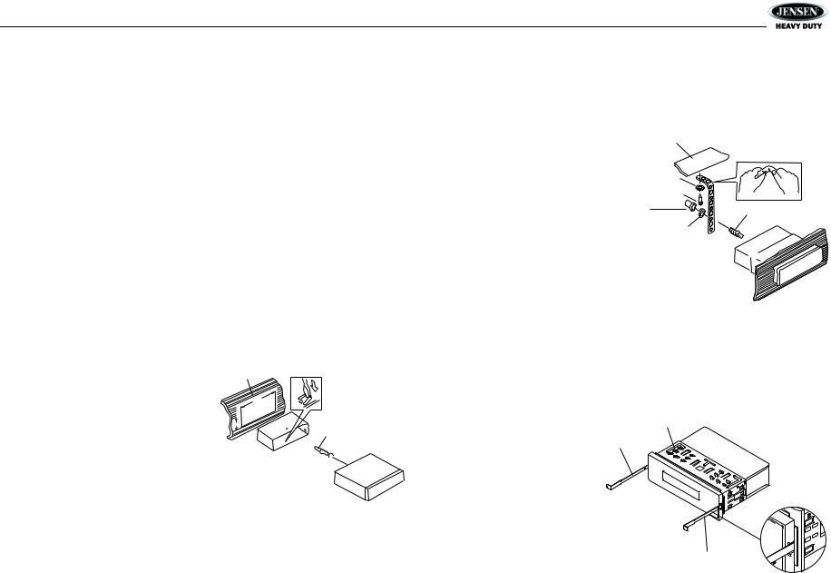
7.Carefully slide the radio into the mounting sleeve making sure it is right-side-up until it is fully seated and the spring clips lock it into place.
8.Attach one end of the
perforated support strap
(supplied) to the screw |
Dashboard |
|
|
|
|
||
stud on the rear of the |
|
Support Strap |
|
chassis using the hex nut |
|
|
|
provided. Fasten the |
Plain Washer |
|
|
other end of the |
Screw (5 x 25mm) |
|
|
perforated strap to a |
|
||
Rubber Bushing |
|
||
secure part of the |
Screw Stud |
||
|
|||
dashboard either above |
Hex Nut (5mm) |
|
|
or below the radio using |
|
|
|
the screw and plain |
|
|
|
washer provided. Bend |
|
|
|
the strap, as necessary, |
|
|
|
to position it. Some |
|
|
|
vehicle installations |
|
|
|
provide cavity for rear |
|
|
support. In these applications, place the rubber bushing over the screw stud and insert the radio.
CAUTION: The perforated rear support strap or rear rubber mounting bushing must be used in the installation of the radio. Installation without either may result in damage to the radio or the mounting surface and void the manufacturer’s warranty.
9.Test radio operation by referring to the operating instructions for the unit.
Removing the Unit
To remove the radio after installation, remove the plastic end caps, insert the removal keys straight back until they click, and then pull the radio out. If removal keys are inserted at an angle, they will not lock properly to release the unit.
Reconnect Battery
When wiring is complete, reconnect the battery negative terminal.
Sleeve
Removal Key
Removal Key
3
 Loading...