


 Loading...
AWM910
Owner’s Manual
1 |
2 |
3 |
4 |
5 |
6 |
|
RPT |
SCAN |
RDM |
H |
M |
|
PUSH PWR |
|
|
|
|
|
VOL |
|
|
|
|
|
|
|
|
ALARM |
|
|
|
|
|
SET |
ON/OFF |
|
|
|
|
EQ |
T/F |
|
|
|
|
|
AUD |
|
MUTE |
AUX |
|
BAND |
CD |
|
|
|
|
||
AUX IN |
|
|
|
|
|
|
|
|
SPK |
SPK |
SPK |
|
|
|
A |
||
|
|
|
B |
A+B |
|
|
|
|
|
||
COMPACT DISC PLAYER
PUSH
RADIO CD COMPACT MUSIC SYSTEM
AWM910
JENSEN

Thank You!
Thank you for choosing a Jensen product. We hope you will find the instructions in this owner’s manual clear and easy to follow. If you take a few minutes to look through it, you’ll learn how to use all the features of your new Jensen receiver for maximum enjoyment.
Table of Contents . . . . . . . . . . . . . . . . . . . . . . . . . . . . . . . . . . . . . . . . . . . . . . . . . . . . . . . . . 2
Features . . . . . . . . . . . . . . . . . . . . . . . . . . . . . . . . . . . . . . . . . . . . . . . . . . . . . . . . . . . . . . . . . 3
Installation . . . . . . . . . . . . . . . . . . . . . . . . . . . . . . . . . . . . . . . . . . . . . . . . . . . . . . . . . . . . . . . 4
Wiring . . . . . . . . . . . . . . . . . . . . . . . . . . . . . . . . . . . . . . . . . . . . . . . . . . . . . . . . . . . . . . . . . . . 5
Basic Operation. . . . . . . . . . . . . . . . . . . . . . . . . . . . . . . . . . . . . . . . . . . . . . . . . . . . . . . . . . . 6
Tuner Operation . . . . . . . . . . . . . . . . . . . . . . . . . . . . . . . . . . . . . . . . . . . . . . . . . . . . . . . . . . 8
CD Operation . . . . . . . . . . . . . . . . . . . . . . . . . . . . . . . . . . . . . . . . . . . . . . . . . . . . . . . . . . . . . 10
Specifications . . . . . . . . . . . . . . . . . . . . . . . . . . . . . . . . . . . . . . . . . . . . . . . . . . . . . . . . . . . . 12
2
AWM910
Features
Features of the Jensen AWM910 mobile audio system include:
•Auto Dimming LCD Display Backlighting
•Backlit Controls and Display
•Electronic AM/FM Tuner
•Three preset EQ Modes
•Rotary Volume Control
•Time/Alarm Clock
•Vertical CD Mechanism for Audio CD, CD-R, CD-RW
•4-Channel Amplified Audio Output (50W Total)
•Front Aux Audio Input (3.5mm stereo jack)
•¼" Headphone Output on Front Panel
3
Installation
Select Mounting Location
Select a mounting location, taking care to avoid the following:
•Places exposed to heat-radiating appliances such as electric heaters
•Adjacent to other equipment that radiates heat
•Poorly-ventilated or dusty places
•Moist or humid locations
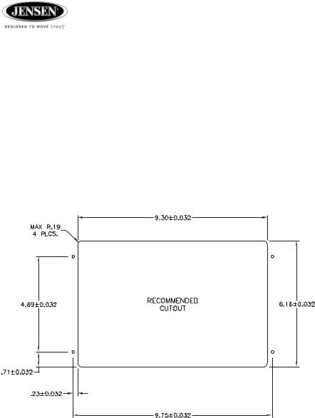
Preparing the Opening
Use the mounting hole diagram (below) to measure and cut a mounting hole, and mount the unit using the four 3x20mm self-tapping screws provided.
Note: Before cutting the mounting hole, make sure the area behind the mounting location is clear of wires and fuel, vacuum and or brake lines.
Mounting Hole Diagram
Mounting the Radio
Route power, speaker and antenna cables through the hole, and connect them to the unit as outlined in the wiring diagram. After ensuring correct connections, test operation.
4
Loading...