


JHD36A
AM/ FM/ RBDS/ WB/ USB/ AUX-IN/ BT/ Sirius XM Ready/ APP Ready Heavy Duty Radio
Installation and Operation Manual

JHD36A
CONTENTS |
|
Introduction............................................................................................................................... |
1 |
Safety Information .................................................................................................................... |
2 |
Installation ................................................................................................................................ |
3 |
Wiring ....................................................................................................................................... |
4 |
Basic Operation ........................................................................................................................ |
5 |
Tuner Operation........................................................................................................................ |
8 |
CD/ MP3/ USB Operation ....................................................................................................... |
10 |
SiriusXM Radio Operation ....................................................................................................... |
11 |
iPod® Operation ...................................................................................................................... |
15 |
Bluetooth Operation................................................................................................................ |
16 |
APP Operation........................................................................................................................ |
17 |
Care and Maintenance ........................................................................................................... |
18 |
Troubleshooting ...................................................................................................................... |
18 |
Specifications ......................................................................................................................... |
19 |
ii
JHD36A
INTRODUCTION
System Features |
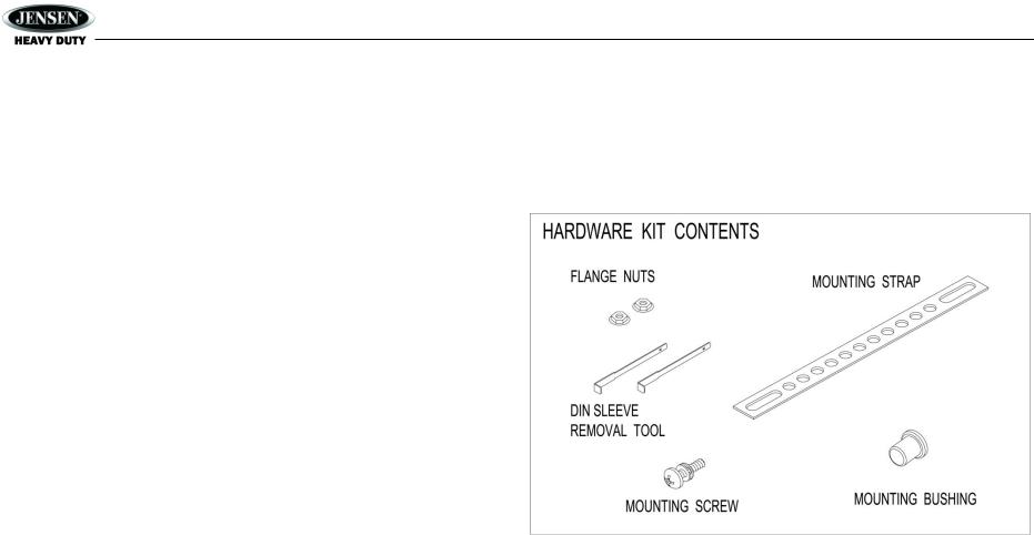
Content List |
||
Features of Jensen JHD36A mobile audio system include: |
Jensen Heavy Duty Radio |
||
Full Dot Matrix LCD |
|
Hardware Kit |
|
|
AM/ FM US/ EURO Tuner with 30 Presets (12AM, 18FM) |
|
Installation Manual |
|
RBDS (Radio Broadcast Data Service) with PTY Search |
|
Quick Reference Guide |
Sirius XM Radio Ready
USB Playback of MP3 and WMA files
CD ESP (Electronic Skip Protection) 30 Sec
iPod Ready (USB Interface)
Weatherband Tuner with SAME Technology
Mute
Bluetooth (Supports A2DP, AVRCP, SPP and HFP)
Pre-set Equalizer – 5 settings (User, Flat, Pop, Classical, Rock)
Electronic Bass, Treble, Balance and Fader Controls
Output Power 45W x 4
Clock 12/ 24 Hour Selectable
Public Announcement (PA) Feature with Optional Microphone
IR Wireless Remote Control Ready (sold separately)
2-Channel Pre-amp Line Level Outputs
2- Wire Power with Non-Volatile Memory and Clock/ Time support
Auxiliary Audio Input (Front 3.5mm Stereo Jack, Rear RCA)
APP Ready
1
JHD36A
SAFETY INFORMATION
When Driving
Keep the volume level low enough to be aware of the road and traffic conditions.
When Washing Your Vehicle
Do not expose the product to water or excessive moisture. Moisture can cause electrical shorts, fire or other damage.
When Parked
Parking in direct sunlight can produce very high temperatures inside your vehicle. Give the interior a chance to cool down before starting playback.
Use the Proper Power Supply
This product is designed to operate with a 12 volt DC negative ground battery system.
Protect the Disc Mechanism
Avoid inserting any foreign objects into the disc slot. Misuse may cause malfunction or permanent damage due to the precise mechanism of this unit.
CAUTION:
THIS MOBILE CD PLAYER IS A CLASS I LASER PRODUCT THAT USES A VISIBLE/ INVISIBLE LASER BEAM WHICH COULD CAUSE HAZARDOUS RADIATION EXPOSURE IF IMPROPERLY DIRECTED. BE SURE TO OPERATE THE MOBILE CD PLAYER AS INSTRUCTED.
USE OF CONTROLS OR ADJUSTMENTS OR PERFORMANCE OF PROCEDURES OTHER THAN THOSE SPECIFIED HEREIN MAY RESULT IN HAZARDOUS RADIATION EXPOSURE. DO NOT OPEN COVERS AND DO NOT ATTEMPT TO REPAIR THE UNIT YOURSELF. REFER SERVICING TO QUALIFIED PERSONNEL.
WARNING:
TO REDUCE THE RISK OF FIRE OR ELECTRIC SHOCK, DO NOT EXPOSE THIS EQUIPMENT TO RAIN OR MOISTURE.
TO REDUCE THE RISK OF FIRE OR ELECTRIC SHOCK AND ANNOYING INTERFERENCE, USE ONLY THE RECOMMENDED ACCESSORIES.
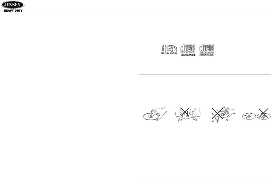
DISC NOTES
Depending on the recording status, conditions of the disc, and the equipment used for recording, some CD-Rs/CD-RWs may not play on this unit. For more reliable playback, please adhere to the following recommendations:
Use CD-RWs with speed 1x to 4x and write with speed 1x to 2x.
Use CD-Rs with speed 1x to 8x and write with speed 1x to 2x.
Do not play a CD-RW which has been written more than 5 times.
Compatible Disc Types
Table 1: General Disc Information
|
Disc Type |
Logo |
Diameter/ |
Playback Time |
|
Playable Sides |
|||
|
|
|
|
|
|
|
|
|
|
|
Audio CD |
|
12cm single side |
74 minutes |
|
|
|
|
|
|
|
|
|
|
NOTE: CD-R and CD-RW discs will not play unless the recording session is closed and the CD is finalized.
Disc Maintenance
A dirty or defective disc may cause sound dropouts while playing. Before playing, wipe the disc using a clean cloth, working from the center hole towards the outside edge. Never use benzene, thinners, cleaning fluids, anti-static liquids or any other solvent.
Insert label side up. |
Do not bend. |
Never touch the |
Wipe clean from this |
|
|
underside of the disc. |
center to the edge. |
Be sure to use only round CDs for this unit and do not use any special shape CDs. Use of special shape CDs may cause the unit to malfunction.
Do not stick paper or tape on the disc. Do not use CDs with labels or stickers attached or that have sticky residue from removed stickers.
Do not expose discs to direct sunlight or heat sources such as hot air-ducts, or leave them in a vehicle parked in direct sunlight where there can be a considerable rise in temperature inside the vehicle.
NOTE: A disc may become scratched (although not enough to make it unusable) depending on how you handle it and other conditions in the usage environment. These scratches are not an indication of a problem with the player.
2
|
|
|
|
JHD36A |
|
|
|
|
|
INSTALLATION |
|
mounting sleeve. |
||
|
|
|
4. |
Place the radio in front of the dashboard opening so the wiring can be brought through the |
This unit is designed for installation in vehicle cabs with an existing 1-DIN radio opening. In |
5. |
Follow the wiring diagram carefully and make certain all connections are secure and |
||
many cases, a special installation kit will be required to mount the radio to the dashboard. See |
|
insulated with crimp connectors or electrical tape to ensure proper operation. |
||
the dealer where the radio was purchased for kit availability. Always check the kit application |
6. |
After completing the |
||
before purchasing to make sure the kit works with your vehicle. |
|
wiring connections, turn |
||
Before you Begin |
|
the unit on to confirm |
||
|
operation (vehicle |
|||
|
|
|
|
|
1. |
Disconnect Battery |
|
accessory switch must be |
|
|
Before you begin, always disconnect the battery negative terminal. |
|
on). If the unit does not |
|
2. |
Remove Transport Screws |
|
operate, recheck all |
|
Important Notes |
|
wiring until the problem is |
||
|
corrected. Once proper |
|||
|
|
|
|
|
|
Before final installation, test the wiring connections to make sure the unit is connected |
|
operation is achieved, |
|
|
properly and the system works. |
|
turn the accessory switch |
|
|
Use only the parts included with the unit to ensure proper installation. The use of |
|
off and proceed with final |
|
|
unauthorized parts can cause malfunctions. |
|
mounting of the chassis. |
|
|
Consult with your nearest dealer if installation requires the drilling of holes or other |
7. |
Carefully slide the radio |
|
|
modifications to your vehicle. |
|
into the mounting sleeve |
|
|
Install the unit where it does not interfere with driving and cannot injure passengers during |
|
making sure it is right-side-up until it is fully seated and the spring clips lock it into place. |
|
|
a sudden or emergency stop. |
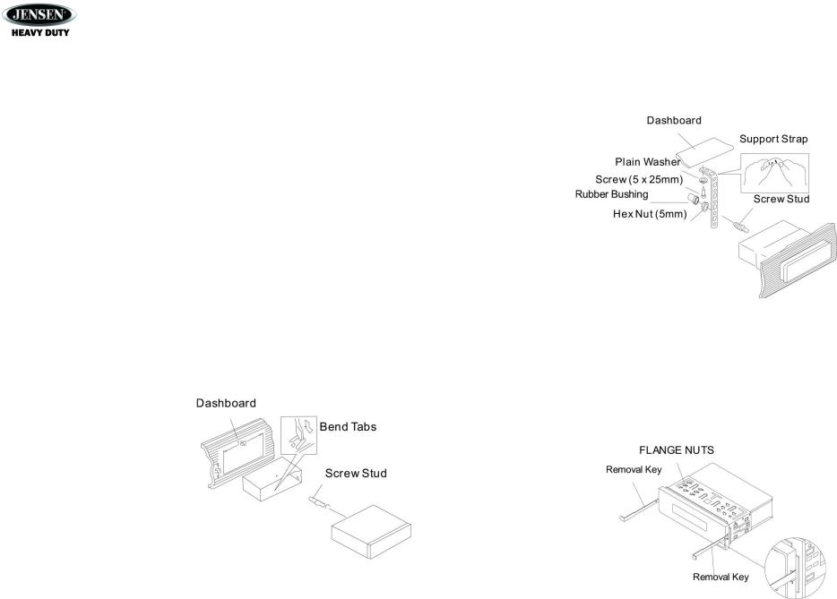
8. |
Attach one end of the perforated support strap (supplied) to the screw stud on the rear of |
|
|
If the installation angle exceeds 30° from horizontal, the unit might not give optimum |
|
the chassis using the hex nut provided. Fasten the other end of the dashboard either |
|
|
performance. |
|
above or below the radio using the screw and plain washer provided. Bend the strap, as |
|
|
Avoid installing the unit where it will be subjected to high temperatures from direct sunlight, |
|
necessary, to position it. Some vehicle installations provide cavity for rear support. In |
|
|
hot air, or from a heater, or subject to excessive dust, dirt or vibration. |
|
these applications, place the rubber bushing over the screw stud and insert. |
|
DIN Front Mount |
|
CAUTION: The perforated rear support strap or rear rubber mounting bushing must |
||
|
be used in the installation of the radio. Installation without either may result in |
|||
|
|
|
|
|
1. |
Slide the mounting sleeve off of the |
|
damage to the radio or the mounting surface and void the manufacturer’s warranty. |
|
|
chassis if it has not already been |
9. |
Test radio operation by referring to the operating instructions for the unit. |
|
|
removed. If it is locked into position, |
Removing the Unit |
||
|
use the removal keys (supplied) to |
|||
|
|
|
||
|
disengage it. The removal keys are |
To remove the radio after installation, |
||
|
depicted in “Removing the Unit” on |
remove the plastic end caps, insert the |
||
|
page 3 . |
removal keys straight back until they |
||
2. |
Check the dashboard opening size by |
click, and then pull the radio out. If |
||
|
sliding the mounting sleeve into it. If |
removal keys are inserted at an angle, |
||
|
the opening is not large enough, |
they will not lock properly to release the |
||
|
carefully cut or files as necessary until |
unit. |
|
|
|
the sleeve easily slides into the |
Reconnect Battery |
||
|
opening. Do not force the sleeve into the opening or cause it to bend or bow. Check that |
|||
|
|
|
||
|
there will be sufficient space behind the dashboard for the radio chassis. |
When wiring is complete, reconnect the |
||
3. |
Locate the series of bend tabs along the top, bottom and sides of the mounting sleeve. |
battery negative terminal. |
||
|
With the sleeve fully inserted into the dashboard opening, bend as many of the tabs |
|
|
|
|
outward as necessary to firmly secure the sleeve to the dashboard. |
|
|
|
3
JHD36A
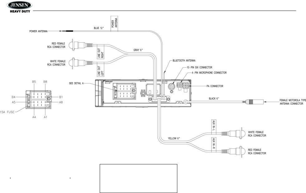
WIRING
DETAIL A
SHOWN FROM PIN VIEW
PIN NO. |
DESCRIPTION |
A1 |
RIGHT REAR SPEAKER (+) |
A2 |
RIGHT FRONT SPEAKER (+) |
|
|
A3 |
LEFT FRONT SPEAKER (+) |
A4 |
LEFT REAR SPEAKER (+) |
A5 |
LEFT REAR SPEAKER ( ) |
A6 |
LEFT FRONT SPEAKER ( ) |
A7 |
RIGHT FRONT SPEAKER ( ) |
A8 |
RIGHT REAR SPEAKER ( ) |
|
|
B1 |
NO CONNECTION |
B2 |
NO CONNECTION |
B3 |
NO CONNECTION |
B4 |
NO CONNECTION |
B5 |
GROUND |
B6 |
NO CONNECTION |
|
|
B7 |
+12V ACC SWITCHED |
B8 |
NO CONNECTION |
WARNING!
Do not connect the +12VDC ACC switched wire to the battery. This wire MUST be connected to the Accessory/ Ignition wire or a +12 volts switched power source.
4

JHD36A
BASIC OPERATION |
Mute |
Power On/ Off/ Radio
Press the rotary encoder POWER/AUDIO button (1) to turn the unit on or press and hold to turn off. The unit will resume at the last mode selected (Tuner, Auxiliary, etc.).
Volume Control
To increase the volume, turn the rotary encoder (1) to the right. To decrease the volume, turn the rotary encoder to the left. While adjusting the volume, the LCD displays a bar graph and numerical representation of the level.
The maximum volume setting is 40.
Press the MUTE button (24) to mute the audio output. Press MUTE again to restore the audio output to the previous level.
Mode
Press the MODE button (4) to select a different mode of operation, as indicated on the display panel. Available modes include the following: Tuner (AM/ FM) > SXM (SiriusXM) > iPod/ USB > CD > Auxiliary > BT Audio. Tuner is the default source when a prior source is no longer available.
NOTE: CD, iPod, USB or SiriusXM (SXM) mode will be skipped if the device is not installed.
NOTE: SiriusXM (SXM) mode will be skipped when the Region menu option is set to
“EURO”.
Reset
The reset button should be activated for the following reasons:
Initial installation of the unit when all wiring is completed
Function buttons do not operate
Error symbol on the display
Use a ball point pen or thin metal object to press the RESET button (23). This may be necessary should the unit display an error code.
Audio Menu
Press the POWER/AUDIO button (1) to access the audio menu. You can navigate through the audio menu items by pressing the POWER/AUDIO button repeatedly. Once the desired menu item appears on the display, adjust that option by turning the rotary encoder (1) within 5 seconds. The unit will automatically exit the audio menu after five seconds of inactivity. The following menu items can be adjusted.
Bass Level
Use the rotary encoder (1) to adjust the Bass level range from “-6” to “+6”.
Treble Level
Use the rotary encoder (1) to adjust the Treble level range from “-6” to “+6”.
Balance
Adjusting Balance controls the relative level between the left and right speakers in each pair.
Use the rotary encoder (1) to adjust the Balance between the left and right speakers from “Left 12” to “Right 12”.
Fader
Adjusting Fade controls the relative level between the front and rear speaker pairs. Use the
5
 Loading...