


Docking Digital HD Radio™ System for iPod ® and iPhone™
Made for
 Pod
Pod
Works with
iPhone
Owner's Manual
JiMS-525i
(iPod and iPhone Not Included)
Please read and follow this Instruction Manual carefully before using the unit and retain it for future reference
- 24 -
IMPORTANT SAFETY
INSTRUCTIONS
WARNING: TO REDUCE THE RISK OF FIRE OR ELECTRIC SHOCK, DO NOT EXPOSE THIS APPLIANCE TO RAIN OR MOISTURE. DANGEROUS HIGH VOLTAGES ARE PRESENT INSIDE THE ENCLOSURE. DO NOT OPEN THE CABINET REFER SERVICING TO QUALIFIED PERSONNEL ONLY.
|
|
|
|
|
|
|
CAUTION |
|
|
|
|
RISK OF ELECTRIC SHOCK |
|
|
|
|
DO NOT OPEN |
|
|
The lightning flash and |
CAUTION: TO REDUCE THE RISK OF |
The exclamation point |
||
arrow head within the |
ELECTRIC SHOCK DO NOT REMOVE |
within the triangle is a |
||
triangle is a warning |
|
COVER (OR BACK) NO USER |
warning sign alerting you |
|
sign alerting you of |
SERVICEABLE PARTS INSIDE. REFER |
of Important Instructions |
||
“dangerous voltage” |
|
SERVICING TO QUALIFIED SERVICE |
accompanying the |
|
inside the product |
|
PERSONNEL |
product |
|
|
|
|
|
|
The Caution marking is located at the bottom of the unit.
The rating plate is located at the bottom of the unit.
CAUTION:
PLEASE READ AND OBSERVE ALL WARNINGS AND INSTRUCTIONS GIVEN IN THIS OWNER'S MANUAL AND THOSE MARKED ON THE UNIT, KEEP THESE INSTRUCTIONS. RETAIN THIS BOOKLET FOR FUTURE REFERENCE.
This set has been designed and manufactured to assure personal safety. Improper use can result in electric shock or fire hazard. The safeguards incorporated in this unit will protect you if you observe the following procedures for installation, use and servicing. This unit does not contain any parts that can be repaired by the user.
The symbol for class II (Double insulation)
DO NOT REMOVE THE CABINET COVER, OR YOU MAY BE EXPOSED TO DANGEROUS VOLTAGE. REFER SERVICING TO QUALIFIED SERVICE PERSONNEL ONLY.
1.Read these Instructions.
2.Keep these Instructions.
3.Heed all Warnings.
4.Follow all instructions.
5.Do not use this apparatus near water.
6.Clean only with a dry cloth.
7.Do not block any of the ventilation openings. Install in accordance with the manufacturer's instructions.
8.Do not install near any heat sources such as radiators, heat registers, stoves, or other apparatus (including amplifiers) that produce heat.
-1 -

IMPORTANT SAFETY
INSTRUCTIONS
9.Do not defeat the safety purpose of the polarized or grounding – type plug. A polarized plug has two blades with one wider than the other. A grounding type plug has two blades and a third grounding prong. The wide blade or the third prong is provided for your safety. If the provided plug does not fit into your outlet, consult an electrician for replacement of the obsolete outlet.
10.Protect the power cord from being walked on or pinched particularly at plugs, convenience receptacles and the point where they exit from the apparatus.
11. Only use attachments/accessories specified by the manufacturer.
12. Use only with a cart, stand, tripod, bracket, or table specified by the manufacturer, or sold with the apparatus. When a cart is used, use caution when moving the cart/apparatus combination to avoid injury from tip-over.
13.Unplug this apparatus during lightning storms or when unused for long periods of time.
14.Refer all servicing to qualified service personnel. Servicing is required when the apparatus has been damaged in anyway, such as power-supply cord or plug is damaged, liquid has been spilled or objects have fallen into the apparatus, the apparatus has been exposed to rain or moisture, does not operate normally, or has been dropped.
FCC NOTICE:
This equipment has been tested and found to comply with the limits for a Class B digital device, pursuant to Part 15 of the FCC Rules. These limits are designed to provide reasonable protection against harmful interference in a residential installation. This equipment generates, uses and can radiate radio frequency energy and, if not installed and used in accordance with the instructions, may cause harmful interference to radio communications.
However, there is no guarantee that interference will not occur in a particular installation. If this equipment does cause harmful interference to radio or television reception, which can be determined by turning the equipment off and on, the user is encouraged to try to correct the interference by one or more of the following measures:
–Reorient or relocate the receiving antenna.
–Increase the separation between the equipment and receiver.
–Connect the equipment into an outlet on a circuit different from that to which the receiver is needed.
–Consult the dealer or an experienced radio/TV technician for help.
Warning:
Changes or modifications to this unit not expressly approved by the party responsible for compliance could void the user's authority to operate the equipment.
–The apparatus shall not be exposed to dripping or splashing and that no objects filled with liquids, such as vases, shall be placed on apparatus.
–Main plug is used as disconnect device and it should remain readily operable during intended use. In order to disconnect the apparatus from the mains completely, the mains plug should be disconnected form the mains socket outlet completely.
–Battery shall not be exposed to excessive heat such as sunshine, fire or the like.
-2 -

TABLE OF CONTENTS |
|
WELCOME ........................................................................................................................................................................ |
4 |
PROTECT YOUR FURNITURE ......................................................................................................................................... |
4 |
ABOUT THIS MANUAL ...................................................................................................................................................... |
4 |
LOCATION OF CONTROLS .............................................................................................................................................. |
4 |
FRONT VIEW .............................................................................................................................................................. |
4 |
REAR VIEW ................................................................................................................................................................ |
5 |
DISPLAY UNIT ............................................................................................................................................................ |
5 |
REMOTE CONTROL SECTION ................................................................................................................................. |
6 |
GETTING STARTED .......................................................................................................................................................... |
6 |
UNPACKING THE HD RADIOTM RECEIVER ............................................................................................................ |
6 |
CONNECTING THE FM ANTENNA WIRE ................................................................................................................. |
6 |
CONNECTING THE HD RADIOTM RECEIVER TO A CABLE RADIO SIGNAL .......................................................... |
7 |
ANTENNA GROUNDING ............................................................................................................................................ |
7 |
NOTICE FOR CABLE TV SYSTEM INSTALLER ........................................................................................................ |
7 |
CONNECTING THE AM LOOP ANTENNA ................................................................................................................. |
7 |
AUX LINE-IN CONNECTION ...................................................................................................................................... |
7 |
CONNECTING AC POWER SUPPLY ........................................................................................................................ |
8 |
ACTIVATING THE REMOTE CONTROL .................................................................................................................... |
8 |
REPLACING THE REMOTE CONTROL BATTERY ................................................................................................... |
8 |
BATTERY PRECAUTIONS ......................................................................................................................................... |
8 |
RADIO OPERATION .......................................................................................................................................................... |
9 |
LISTENING TO THE RADIO ...................................................................................................................................... |
9 |
TO PRESET CHANNELS ........................................................................................................................................... |
10 |
TO RECEIVE PRESET STATIONS ............................................................................................................................ |
10 |
HD RADIOTM MULTICAST CHANNELS (FM ONLY) ................................................................................................ |
10 |
SPECIAL INFORMATION ABOUT DELAY IN THE HD RADIOTM SYSTEM ............................................................. |
11 |
RBDS (RADIO BROADCAST DATA SYSTEM) ......................................................................................................... |
11 |
iTunes Tagging ............................................................................................................................................................. |
12 |
TO STORE SONG TAG(S) ......................................................................................................................................... |
12 |
PURCHASING SONG(S) WITH ITUNES ................................................................................................................... |
12 |
AUX OPERATION .............................................................................................................................................................. |
13 |
iPod ADAPTORS .............................................................................................................................................................. |
13 |
DOCKING YOUR IPOD .............................................................................................................................................. |
14 |
DOCKING YOUR IPHONE ......................................................................................................................................... |
15 |
CONNECTING THE S-VIDEO (FOR IPOD VIDEO OUTPUT) ......................................................................................... |
16 |
GENERAL SET UP ..................................................................................................................................................... |
16 |
FOR PHOTO VIEW (FOR IPOD WITH COLOR DISPLAY ONLY – EXCLUDING IPOD NANO) ................................ |
16 |
CONNECTING THE S-VIDEO (FOR IPHONE VIDEO OUTPUT) .................................................................................... |
16 |
FOR VIDEO VIEW (FOR IPHONE WITH VIDEO ONLY) .......................................................................................... |
16 |
USING HEADPHONES (NOT INCLUDED) ....................................................................................................................... |
17 |
CLOCK SETTING ............................................................................................................................................................... |
17 |
SETTING THE TIME ................................................................................................................................................... |
17 |
SETTING THE ALARM (S) ......................................................................................................................................... |
18 |
CLOCK LIGHT OPERATION ............................................................................................................................................. |
18 |
ALARM OPERATION ......................................................................................................................................................... |
19 |
WAKE TO RADIO, IPOD OR ALARM ........................................................................................................................ |
19 |
SNOOZE OPERATION ...................................................................................................................................................... |
19 |
SLEEP OPERATION .......................................................................................................................................................... |
20 |
SETTING SLEEP TIMER ............................................................................................................................................ |
20 |
ADJUSTING THE SLEEP PERIOD ............................................................................................................................ |
20 |
SLEEP AND WAKE TO BUZZER/iPod/RADIO ............................................................................................................... |
20 |
CARE AND MAINTENANCE .............................................................................................................................................. |
21 |
CLEANING THE UNIT ................................................................................................................................................ |
21 |
SPECIFICATIONS .............................................................................................................................................................. |
21 |
TROUBLESHOOTING GUIDE ........................................................................................................................................... |
22 |
SERVICE ............................................................................................................................................................................ |
23 |
- 3 -
WELCOME
Thank you for purchasing the JENSEN JiMS-525i HD RadioTM System.
Before operating the unit, please read this manual thoroughly and retain it for future reference.
PROTECT YOUR FURNITURE!!
This system is equipped with non-skid rubber 'feet' to prevent the product from moving when you operate the controls. These 'feet' are made from non-migrating rubber material specially formulated to avoid leaving any marks or stains on your furniture. However certain types of oil based furniture polishes, wood preservatives, or cleaning sprays may cause the rubber 'feet' to soften, and leave marks or a rubber residue on the furniture.
To prevent any damage to your furniture we strongly recommend that you purchase small self-adhesive felt pads, available at hardware stores and home improvement centers everywhere, and apply these pads to the bottom of the rubber 'feet' before you place the product on fine wooden furniture.
ABOUT THIS MANUAL
Instructions in this manual describe using the controls on the remote. You can also use the controls on the main unit if they have the same or similar names as those on the remote.
LOCATION OF CONTROLS
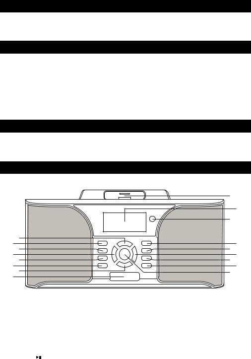
Front View
|
|
|
17 |
|
|
|
16 |
|
|
|
15 |
|
1 |
|
|
|
2 |
|
14 |
|
3 |
|
13 |
|
4 |
|
12 |
|
5 |
|
11 |
|
6 |
|
10 |
|
7 |
|
9 |
|
8 |
|
|
|
|
|
|
1. |
Volume + Button |
10. |
ALARM 2 Button |
2. |
STANDBY/ON Button |
11. ALARM 1 Button |
|
3. |
EQ Button |
12. |
Skip : Forward/Tuning Up Button |
4. |
Skip 9 Backward/Tuning Down Button |
13. |
SLEEP Button |
5. |
FUNCTION Button |
14. |
SET/FM MODE Button |
6. |
BAND Button |
15. |
Remote Sensor |
7. |
Volume – Button |
16. |
Display |
8. |
SNOOZE/LIGHT Button |
17. iPod Connector and Docking Bay |
|
9. |
Play/Pause / iTunes®Tag Button |
|
|
|
|
- 4 - |
|

LOCATION OF CONTROLS (Continued)
Rear View
1 |
2 |
3 |
4 |
|
5 |
6 |
7 |
|
|
|||||||||||
|
|
|
|
|
|
|
|
|
|
|
|
|
|
|
|
|
|
|
|
|
|
|
|
|
|
|
|
|
|
|
|
|
|
|
|
|
|
|
|
|
|
|
|
|
|
|
|
|
|
|
|
|
|
|
|
|
|
|
|
|
|
|
|
|
|
|
|
|
|
|
|
|
|
|
|
|
|
|
|
|
|
|
|
|
|
|
|
|
|
|
|
|
|
|
|
|
|
|
|
|
|
|
|
|
|
|
|
|
|
|
|
|
|
|
|
|
|
|
|
|
|
|
|
|
|
|
|
|
|
|
|
|
|
|
|
|
|
|
|
|
|
|
|
|
|
|
|
|
|
|
|
|
|
|
|
|
|
|
|
|
|
|
|
|
|
|
|
|
|
|
|
|
|
|
|
|
|
|
|
|
|
|
|
|
|
|
|
|
|
|
|
|
|
|
|
|
|
|
|
|
|
|
|
|
|
|
|
|
|
|
|
|
|
|
|
|
|
|
|
|
|
|
|
|
|
|
|
|
|
|
1. |
AC INPUT SOCKET |
5. |
AUX LINE-IN Jack |
2. |
AM Antenna Connector |
6. |
HEADPHONE Jack |
3. |
S-VIDEO Output (5th Gen iPod) |
7. |
RESET Switch |
4. |
FM Antenna Connector |
|
|
Display Unit
1 |
2 |
3 |
4 |
5 |
6 |
7 |
8 |
9 |
10 |
|
FM |
|
|
|
|
ST |
|
|
|
|
PM |
|
|
|
|
MHz |
|
|
|
|
AM |
|
|
|
|
KHz |
|
|
|
1. |
Band/AM-PM Indicator |
6. |
ALARM 2 Indicator |
2. |
iPod Icon |
7. |
SLEEP Indicator |
3. |
HD RadioTM Icon |
8. |
FM STEREO Indicator |
4. |
Time/Frequency Reading |
9. |
Frequency Unit |
5. |
ALARM 1 Indicator |
10. |
RBDS Messages/FUNCTION Indicator |
|
|
- 5 - |
|
LOCATION OF CONTROLS (Continued)
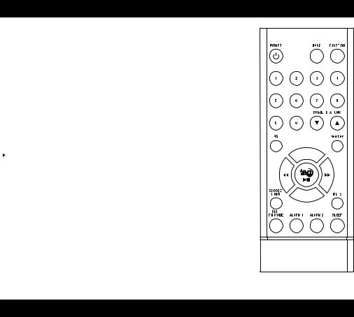
Remote Control Section
POWER |
Turn the Radio On/Off |
|
|||||||||||
BAND |
Select AM/FM Band |
|
|||||||||||
FUNCTION |
Selects Radio, iPod or Aux Modes |
|
|||||||||||
0 – 9 |
Numeric buttons |
|
|||||||||||
PRESET STATIONS 6 |
Memory Stations Down |
|
|||||||||||
PRESET STATIONS 5 |
Memory Stations Up |
|
|||||||||||
EQ |
Equalizer Options |
|
|||||||||||
MEMORY |
Program Preset Stations |
|
|||||||||||
+, – |
Volume Up and Down |
|
|||||||||||
|
|
|
Play/Pause/ iTunes® Tag |
|
|
|
|
|
|
|
|||
|
|
|
|
|
|
|
|
|
|
||||
: |
Skip Forward/Tuning Up |
|
|||||||||||
9 |
Skip Backward/Tuning Down |
|
|
|
|
|
|
|
|
|
|||
|
|
|
|
|
|
|
|
|
|||||
|
|
||||||||||||
SNOOZE/LIGHT |
Silences the Alarm Temporarily/ |
|
|||||||||||
MUTE |
Switch Backlight On/Off |
|
|
|
|||||||||
Mute the System Sound |
|
||||||||||||
SET/FM MODE |
Set Time/Select FM ST or MONO |
|
|||||||||||
ALARM 1 |
Set Alarm 1 |
|
|
||||||||||
ALARM 2 |
Set Alarm 2 |
|
|
||||||||||
SLEEP |
Set Sleep Timer On |
|
|
||||||||||
|
|
|
|
|
|
|
|
|
|
|
|
|
|
GETTING STARTED
Unpacking the HD RadioTM Receiver
Please save all the original packaging. It provides the safest way to transport your unit.
Note: This HD RadioTM Receiver is not designed for automotive use.
NOTE: The JiMS-525i is not magnetically shielded and may cause color distortion on the screen of some TVs or video monitors. To avoid this, you may need to move the unit further away from the TV or monitor if unnatural color shifts or image distortion occurs.
Connecting the FM Antenna Wire (included)
1.Push the connector plug on the end of the antenna wire onto the FM Antenna Connector at the rear of the radio.
2.Straighten out the Antenna to its full length and orient the wire for the best reception.
- 6 -
GETTING STARTED (Continued)
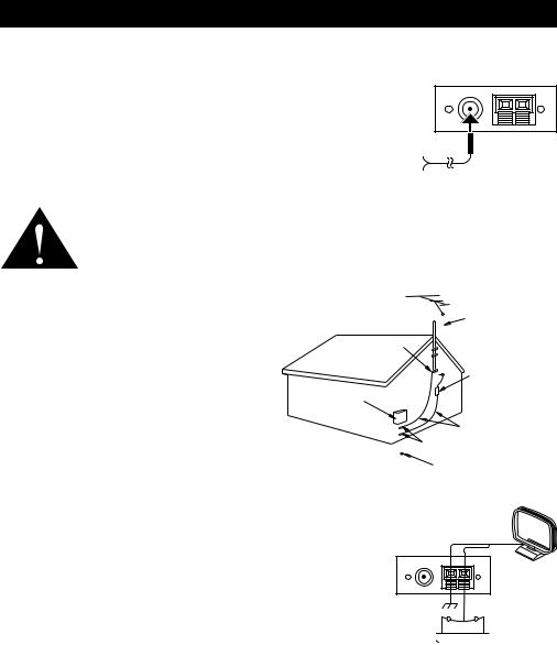
Connecting FM / HD RadioTM Receiver Antenna / to a Cable Radio Signal
This Radio's FM Antenna Connector is a standard connector that will accept either the FM Antenna wire (included) or the cable FM feed from most cable systems that provide FM programming. To connect the included FM Antenna wire, slide the black plastic end of the antenna wire onto the center post of the antenna connector on the back of the unit. To connect your Radio to the
FM signal available from some cable TV providers, contact your cable TV provider for assistance and also to find out if HD RadioTM broadcast signals are available through the cable line. As of the writing of this manual, HD
RadioTM signals are not being rebroadcast via cable providers.
FM / HD RADIO AM RADIO ANTENNA ANTENNA
CONNECTOR CONNECTOR
FM / HD RADIO
ANTENNA WIRE
Be sure that the installation includes a splitter that will filter the signal to prevent any re-emission of the TV spectrum through the Radio, so that only the FM band, not the cable TV signal, is transmitted to the Radio.
Antenna Grounding |
|
|
|
|
|
|
Antenna Lead In Wire |
Example of antenna grounding, per the National Electrical |
|
|
|||||
|
|||||||
|
|
|
|||||
Code, ANSI/NFPA 70. |
Ground Clamp |
|
|
|
|||
|
|
|
|
||||
|
|
|
|
|
|
|
Antenna |
Notice for Cable TV System Installer |
|
|
|
|
|
|
Discharge Unit |
|
|
|
|
|
|
||
|
|
|
|
|
|
(Nec Section 810-20) |
|
Please make note of Article 820-40 of the NEC |
Electric Service |
|
|
|
|
|
|
(of USA) that provides guidelines for proper |
Equipment |
|
|
|
|
|
|
|
|
|
|
|
|
Grounding Conductors |
|
grounding. In particular, this standard specifies |
|
|
|
|
|
|
(Nec Section 810-21) |
that the cable ground shall be connected to the |
Nec-National |
|
|
|
Ground Clamps |
||
|
|||||||
Electrical Code |
|
||||||
grounding system of the building, as close to the |
|
|
|
|
|||
|
|
|
|
|
|
|
|
point of cable entry as is practical. |
Power Service Grounding Electrode System |
||||||
|
(Nec Art 250, Part H ) |
||||||
Connecting the AM Loop Antenna
If AM reception is weak for improvement connect the provided Loop
Antenna as describe below:
1.Push to open the 2 receptacles of the AM antenna terminals and insert 2 open-end wires of the AM loop antenna into them.
2.Release the 2 AM antenna terminal handles to hold the AM loop antenna wires in place.
3.Orient the AM loop antenna for the best reception.
AM loop antenna
AM outdoor 


 antenna
AUX LINE-IN Connection
Connect one end of the Audio line cable (Included) to the AUX Input jack at the back of the Radio and the other end of the Audio line cable to your external audio player, such as a CD, MP3 etc.
- 7 -
 Loading...