


JWM70A
MOBILE AUDIO SYSTEM
Installation and Owner's Manual

|
JWM70A |
Introduction.............................................................................................................................. |
3 |
Disc Notes................................................................................................................................ |
4 |
Installation............................................................................................................................... |
5 |
Wiring...................................................................................................................................... |
6 |
Basic Operation........................................................................................................................ |
7 |
Tuner Operation...................................................................................................................... |
10 |
Disc Operation........................................................................................................................ |
11 |
DVD/VCD Operation ............................................................................................................... |
12 |
MP3/USB Operation................................................................................................................ |
14 |
Bluetooth Operation................................................................................................................ |
16 |
App Operation........................................................................................................................ |
17 |
Remote Control Operation....................................................................................................... |
18 |
DVD Setup Menu..................................................................................................................... |
20 |
Care and Maintenance............................................................................................................. |
22 |
Troubleshooting...................................................................................................................... |
22 |
Specifications......................................................................................................................... |
23 |
FCC Notice............................................................................................................................. |
23 |
INTRODUCTION
Thank You!
JWM70A
ŸAvoid Moisture.
To reduce the risk of fire or electric shock, do not expose this equipment to rain or moisture.
Thank you for choosing a Jensen product. We hope you will find the instructions |
Ÿ Avoid Cleaning Products. |
|
The front of this unit should only be cleaned with a slightly damp cloth. Do not |
||
in this owner’s manual clear and easy to follow. If you take a few minutes to look |
||
use cleansers. |
||
through it, you’ll learn how to use all the features of your new Jensen receiver for |
||
Ÿ Use Recommended Accessories. |
||
maximum enjoyment. |
||
TO REDUCE THE RISK OF FIRE OR ELECTRIC SHOCK AND ANNOYING |
||
|
||
Features |
INTERFERENCE, USE ONLY THE RECOMMENDED ACCESSORIES. |
|
|
Features of Jensen JWM70A mobile audio system include:
ŸDigital AM/FM Tuner/30 Preset stations (12 AM/18 FM)
ŸBluetooth Ready with A2DP/AVRCP Streaming Audio
ŸAPP Ready
ŸPre-set Equalizer -5 settings (User > Flat > Pop > Classical > Rock)
ŸElectronic Bass, Treble, Balance and Fader Controls
ŸDVD/CD-R/RW and MP3 Compatible
ŸHDMI Video Output with JCOM link
ŸHDMI ARC
ŸTime/Alarm Clock
ŸWhite LED Backlit LCD
Ÿ1/8" Front Auxiliary Audio Input
ŸRear Audio RCA Inputs/Outputs
ŸUSB Playback of MP3/WMA Files
Ÿ3 Zone / 8 Speaker Output
ŸIndependent Zone Volume Control
ŸWireless Remote Control Included
CAUTION: This mobile DVD player is a Class I laser product that uses a visible/invisible laser beam which could cause hazardous radiation exposure if improperly directed. Be sure to operate the mobile DVD player as instructed. Use of controls or adjustments or performance of procedures other than those specified herein may result in hazardous radiation exposure. Do not open covers and do not attempt to repair the unit yourself.
Refer servicing to qualified personnel.
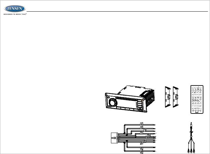
Packing List
JWM70A |
SCREW COVER |
Remote Control |
||||||||||||
|
|
|
|
|
|
|
|
|
|
|
|
|
|
|
|
|
|
|
|
|
|
|
|
|
|
|
|
|
|
|
|
|
|
|
|
|
|
|
|
|
|
|
|
|
|
|
|
|
|
|
|
|
|
|
|
|
|
|
|
|
|
|
|
|
|
|
|
|
|
|
|
|
|
|
|
|
|
|
|
|
|
|
|
|
|
|
|
|
|
|
|
|
|
|
|
|
|
|
|
|
|
|
|
|
|
|
|
|
|
|
|
|
|
|
|
|
|
|
|
|
|
|
|
|
|
|
|
|
|
|
|
|
|
|
Precautions |
AUX AUDIO/VIDEO |
20-PIN Speaker Wire |
|
Ÿ Use the Proper Power Supply. |
CABLE |
This product is designed to operate with a 12 volt DC, negative ground |
|
battery system(the standard system in a North American vehicle). |
|
Ÿ Protect the Disc Mechanism. |
|
Avoid inserting any foreign objects into the slot of this player. Failure to |
|
observe this may cause malfunction due to the precise mechanism of this |
|
unit. |
|
Ÿ Use Authorized Service Centers. |
|
Do not attempt to disassemble or adjust this precision product; contact a |
|
professional for assistance. |
|
3

JWM70A
DISC NOTES
Depending on the recording status, conditions of the disc, and the equipment used for recording, some CD-Rs/CD-RWs may not play on this unit. For more reliable playback, please adhere to the following recommendations:
ŸUse CD-RWs with speed 1x to 4x and write with speed 1x to 2x.
ŸUse CD-Rs with speed 1x to 8x and write with speed 1x to 2x.
ŸDo not play a CD-RW which has been written more than 5 times.
NOTE: CD-R and CD-RW discs will not play unless the recording session is closed and the CD is finalized.
Disc Maintenance
ŸA dirty or defective disc may cause sound dropouts while playing. Before playing, wipe the disc using a clean cloth, working from the center hole towards the outside edge. Never use benzene, thinners, cleaning fluids, anti-static liquids or any other solvent.
ŸBe sure to use only round CDs for this unit and do not use any special shape CDs. Use of special shape CDs may cause the unit to malfunction.
ŸDo not stick paper or tape on the disc. Do not use CDs with labels or stickers attached or that have sticky residue from removed stickers.
ŸDo not expose discs to direct sunlight or heat sources such as hot air-ducts, or leave them in a vehicle parked in direct sunlight where there can be a considerable rise in temperature inside the vehicle.
Insert label side up. |
Do not bend. |
Never touch the |
Wipe clean from this |
underside of the disc. center to the edge.
NOTE: A disc may become scratched (although not enough to make it unusable) depending on how you handle it and other conditions in the usage environment. These scratches are not an indication of a problem with the player.
4
|
|
JWM70A |
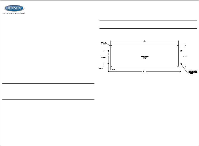
INSTALLATION |
NOTE: Before cutting the mounting hole, make sure the area behind the |
|
. |
mounting location is clear of wires, fuel and vacuum or brake lines. |
|
It's a good idea to read all of the instructions before beginning the installation. |
||
We recommend having your Jensen JWM70A installed by a reputable RV |
|
|
dealership. |
|
|
Tools and Supplies
You will need these tools and supplies to install your JWM70A:
ŸPhillips screw driver
ŸWire cutters and strippers
ŸTools to remove existing radio (screwdriver, socket wrench set or other tools)
ŸElectrical tape
ŸCrimping tool
ŸVolt meter/test light
ŸCrimp connections
Ÿ16 gauge wire for power connections
Ÿ16 –18 gauge speaker wire
ŸFour M3x20mm (3/32 x 0.75") screws
Disconnecting the Battery
To prevent a short circuit, be sure to turn off the ignition and remove the negative (-) battery cable prior to installation.
NOTE: If the JWM70A is to be installed in a vehicle equipped with an onboard drive or navigation computer, do not disconnect the battery cable. If the cable is disconnected, the computer memory may be lost. Under these conditions, use extra caution during installation to avoid causing a short circuit.
Selecting the Mounting Location
Select a mounting location, taking care to avoid the following:
ŸPlaces exposed to heat-radiating appliances such as electric heaters
ŸAdjacent to other equipment that radiates heat
ŸPoorly-ventilated or dusty places
ŸMoist or humid locations
"
 "
"

 "
"
 "
"
 "
"
 "
"


 "
"
 "
"

 "
"
 "
"

 "
"
 "
"

 "
"
 "
"
Mounting the Radio
ŸUse the mounting hole diagram to measure and cut a mounting hole
ŸRoute power, speakers, AV, and antenna cables through the hole and connect
ŸCheck and ensure correct operation
ŸMount the unit using four M3x20mm (3/32 x 0.75") screws
ŸAttach the screw covers
5

|
|
|
JWM70A |
|
WIRING |
|
|
WARNING: Wiring harness comes with stripped and tinned leads to aid in the |
|
The wiring diagram depicts all the wiring connections required for proper |
installation process. Any unused speaker wires must have their exposed ends cut |
|||
off or insulated individually. |
||||
operation of the unit. |
|
|
||
|
|
|
||
10 |
1 |
WIRING HARNESS |
|
|
CONNECTOR |
|
|||
|
|
(SEE DETAIL A) |
|
|
10A |
11 |
|
|
|
20 |
|
|
||
DETAIL A |
|
|
|
|
SHOWN FROM PIN VIEW |
|
|
|
|
PIN NO. |
WIRE COLOR |
DESCRIPTION |
1 |
PINK/BLACK |
RIGHT (C) SPEAKER (-) |
2 |
PINK |
RIGHT (C) SPEAKER (+) |
3 |
DARKGREEN |
LEFT (C) SPEAKER (+) |
4 |
DARK GREEN/BLACK |
LEFT (C) SPEAKER (-) |
5 |
BROWN/BLACK |
LEFT (B) SPEAKER (-) |
6 |
GRAY |
FRONT RIGHT (A) SPEAKER (+) |
7 |
GRAY/BLACK |
FRONT RIGHT (A) SPEAKER (-) |
8 |
EMPTY |
NO CONNECTION |
9 |
WHITE/BLACK |
FRONT LEFT (A) SPEAKER (-) |
10 |
WHITE |
FRONT LEFT (A) SPEAKER (+) |
11 |
ORANGE |
RIGHT (B) SPEAKER (+) |
12 |
ORANGE/BLACK |
RIGHT (B) SPEAKER (-) |
13 |
BROWN |
LEFT (B) SPEAKER (+) |
14 |
BLUE |
POWER ANTENNA |
15 |
RED |
ACC/ IGN (+) (18GA) |
16 |
BLACK |
GROUND (18GA) |
17 |
VIOLET |
RIGHT REAR (A) SPEAKER (+) |
18 |
VIOLET/BLACK |
RIGHT REAR (A) SPEAKER (-) |
19 |
LIGHT GREEN/BLACK |
LEFT REAR (A) SPEAKER (-) |
20 |
LIGHT GREEN |
LEFT REAR (A) SPEAKER (+) |
CONNECTIONS
The diagram below depicts all the available audio/video connections available to use with your system.
|
FIXED AUDIO |
|
VARIABLE AUDIO |
OUTPUT(RIGHT, |
|
OUTPUT |
LEFT) |
VIDEO |
(RIGHT,LEFT) |
|
|
|
OUTPUT |
|
|
|
|
AM/FM ANTENNA |
|
|
SOCKET |
|
|
AUDIO INPUT |
|
HDMI |
|
|
|
(RIGHT, LEFT) |
|
|
6

|
|
|
|
|
|
|
JWM70A |
BASIC OPERATION |
|
|
|
|
|
Mode |
|
|
|
|
|
|
1. Press the MODE button (15), the LCD will display “MODE” and access mode |
||
|
20 |
|
19 |
18 |
17 |
16 |
selection. |
|
|
2. Press the MODE button, |<< or >>| buttons (6, 8), or rotate the VOL/ENTER knob |
|||||
|
|
|
|
|
|
|
|
|
|
|
|
|
|
|
to cycle through the available modes and choose the desired mode. Available |
|
|
|
|
|
|
|
modes are AM, FM, FRONT AUX, REAR AUX, HDMI ARC, DISC and USB. |
1 |
|
|
|
|
|
15 |
3. Press ENTER knob (4) to confirm the mode selection. |
|
|
|
|
|
Audio Menu Setting |
||
|
|
|
|
|
14 |
||
|
|
|
|
|
|
||
|
|
|
|
|
|
13 |
1.Press the SETTINGS button (14) to access the audio menu. |
|
|
|
|
|
|
12 |
2.Press the |<< or >>| buttons (6, 8) or SETTINGS button repeatedly to navigate |
|
|
|
|
|
|
through the audio menu items. |
|
|
|
|
|
|
|
11 |
|
2 |
|
|
|
|
|
3.Once the desired menu item appears on the display, adjust that option by rotating |
|
|
|
|
|
|
|
the VOL/ENTER knob (4) clockwise or counter-clockwise within 5 seconds. |
|
|
|
|
|
|
|
|
4.Press the Back button (2) to confirm your selection and exit audio menu. The unit |
|
|
|
|
|
|
|
will automatically exit the audio menu after 5 seconds of inactivity. |
|
|
|
|
|
|
|
The following items can be adjusted: |
3 4 |
5 |
6 |
7 |
8 |
|
9 10 |
Ÿ BASS: Adjust the Bass level from "-7" to "+7". |
Power |
|
|
|
|
|
|
Ÿ TREBLE: Adjust the treble from "-7" to "+7". |
|
|
|
|
|
|
Ÿ BALANCE: Adjust the Balance between the left and right speakers output from |
|
Press the POWER button (1) to turn the unit on. |
|
|
|
"LEFT 7" (full left) to "RIGHT 7" (full right). |
|||
The unit will resume at the last mode (Tuner, Aux, etc.). |
|
“BALANCE 0” indicates equal balance between the left and right speakers. |
|||||
Zones Volume Control |
|
|
|
|
|
|
Ÿ FADE: Adjust the speaker fade between the rear and front speakers from “REAR |
|
|
|
|
|
|
7” (full rear) to “FRONT 7” (full front). |
|
1. Press the ZONES button (5) to enter the zone menu. |
|
“FADE 0” indicates equal balance between the rear and front speakers. |
|||||
2. While in the zone menu, press ZONES, ENTER (4), or the |<< or >>| buttons |
Ÿ LOUDNESS: Toggle the loudness on/off. When listening to music at low |
||||||
(6, 8) to change the active zone (ZONE A, ZONE B and ZONE C) for volume |
volumes, this feature will boost the bass/treble range to compensate for the |
||||||
adjustment control. |
|
|
|
|
|
|
characteristics of human hearing. |
NOTE: Zone A also controls the output of the rear line level audio out. |
Ÿ EQUALIZATION: Choose one of the following pre-defined bass and treble |
||||||
3. Rotate the VOL/ENTER knob (4) clockwise toincrease or counter-clockwise to |
curves: POP > CLASSICAL > ROCK > FLAT. |
||||||
decrease the active zone's volume. |
|
|
|
|
System Menu Setting |
||
|
|
|
|
|
|
|
|
NOTE: Set the zone volume to '0' to turn off the zone. |
|
1. Press and hold the SETTINGS button (14) for 2 seconds to access the system |
|||||
Each zone has a maximum volume setting of '40'.While adjusting the volume, the |
menu. |
||||||
LCD displays numerical representation of the level. |
|
|
2. Press the |<< or >>| buttons (6, 8) or SETTINGS button repeatedly to navigate |
||||
Zone Mute |
|
|
|
|
|
|
through the system menu items. |
While in zone menu (see above), press and hold the ENTER knob button to mute |
3. Once the desired menu item appears on the display, adjust that option by rotating |
||||||
the VOL/ENTER knob clockwise or counter-clockwise within 5 seconds. |
|||||||
the audio output of the active zone's volume. Press and hold again to restore the |
4. Press the Back button (2) to confirm your selection and exit audio menu. The unit |
||||||
previous volume level. |
|
|
|
|
|
|
will automatically exit the audio menu after 5 seconds of inactivity. |
Pause / Mute
During RADIO / FRONT AUX / REAR AUX / HDMI ARC mode, press the || button
(7) to mute the audio output for all zones. Press again to restore the previous volume level.
During USB / DVD / BT mode, press the || button to pause playback. Press again to resume playback.
The following items can be adjusted:
–BLUETOOTH DEVICE (Lock/Unlock, Disconnect/Connect, Delete): View, lock and delete from a list of previously paired mobile phone device models.
–BEEP (ON/OFF): Turn the audible beep On/Off (heard when functions/buttons are selected).
7
JWM70A
Note: Beep tone off will not affect the audible tone of the alarm clock.
–REGION (USA/EUROPE): Set frequency spacing for various regions.
–BLUETOOTH (ON/OFF): Choose “Bluetooth On” or Bluetooth Off”.
–PRESET VOL (1-40): Select an automatic turn on volume.
–RESET <ENTER>: Press the ENTER button to return the JWM70A to factory default settings.
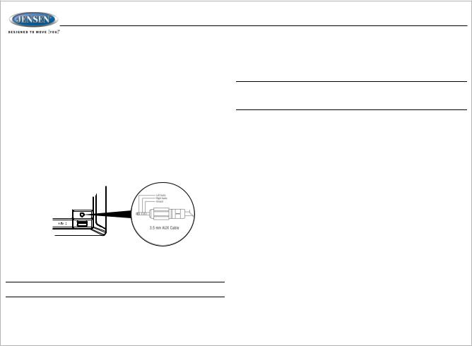
Auxiliary Input Function
When a portable audio device is connected to the unit, press the MODE button (15) repeatedly until FRONT AUX / REAR AUX mode is selectable, then press ENTER (4) knob to enter the FRONT AUX / REAR AUX mode. To connect a portable audio device, insert a standard 3.5mm (audio line output or headphone output from your portable CD / MP3 or other media player) into the AUX connector (AUX FRONT) (11) on the front of the unit or the AUX-IN RCA jack
(AUX REAR) on the left chassis of the unit.
Auxiliary Input Connector
For front panel audio input, an external audio source can be connected to the front panel audio input with a 3.5mm audio cable adapter. Connect the device to the AUX connector (11) on the front panel.
In addition to front panel auxiliary input source, the unit can also be connected to the RCA audio input through the AUX-IN RCA jack on the left chassis of the unit.
USB Interface Connector
You can connect a USB device directly to USB interface (10) on the front of the JWM70A for playback of compatible files. Press the MODE button repeatedly until USB mode is selectable. Refer to “MP3/USB Operation” on page 13 for additional operating instructions.
NOTE: USB will not support Apple device playback. The USB input supplies up to 1A of charging current.
Liquid Crystal Display (LCD)
The current activated functions and time are shown on the LCD panel (19).
Dimming control
1.Press the DIM button (17) on the front panel to turn the dimmer On (selected brightness level) and press again to turn the dimmer Off (maximum brightness level).
2.Press & Hold the DIM button (17) to access DIMMER LEVEL menu.
3.Rotate the volume knob clockwise to increase or counter-clockwise to decrease the brightness of button and LCD backlight from “BRIGHTNESS 0” to “BRIGHTNESS 8”. “BRIGHTNESS 0” indicates the LCD backlight is turned off.
4.Press the BACK button (2) to confirm your selection and exit menu.
NOTE: LCD panels may take longer to respond when subjected to cold temperatures for an extended period of time. In addition, the visibility of the numbers on the LCD may decrease slightly. The LCD display will return to normal when the temperature increases to a moderate range.
Time Menu Settings
1.Press the TIME button (18) to access time menu settings.
2.Press the |<< or >>| buttons (6, 8) or TIME button repeatedly to navigate the time menu.
3.Once the desired time menu item appears on the display, adjust that option by rotating the VOL/ENTER knob clockwise or counter-clockwise within 5 seconds.
The following items can be adjusted:
ŸSLEEP TIMER: select the sleep time from 0 (OFF), 15, 30, 45 or 60 minutes. The sleep timer will automatically turn off the JWM70A in designated number of minutes.
ŸALARM (ON/OFF): to turn the alarm function on or off.
ŸALARM SET: The hour clock digit will flash, Rotate the VOL/ENTER knob clockwise or counter-clockwise to adjust the hour. Press the ENTER knob to access the minute adjustment. Press the ENTER knob again to save the alarm time and return to ALARM ON/OFF setting.
ŸCLOCK SET: The hour clock digit will flash, Rotate the VOL/ENTER knob clockwise or counter-clockwise to adjust the hour. Press the ENTER knob to access the minute adjustment. Press the ENTER knob again to save the clock time.
Press the BACK button (2) to confirm your selection and exit time menu. The unit will automatically exit the audio menu after 5 seconds of inactivity.
Remote Sensor
Infrared receiver is located on the front panel to receive infrared signal emitted by
the remote control.
Reset
The reset button should be activated for the following reasons:
ŸInitial installation of the unit when all wiring is completed
ŸFunction buttons do not operate
ŸError symbol on the display
HDMI ARC
Use a ball point pen or thin metal object to press the RESET button (3).
Connect HDMI cable to JENSEN TV with ARC function and JWM70A radio head unit. If the set up and operation is correct, the TV audio will come out from the speaker of the head unit after switching to HDMI ARC mode.
8
 Loading...