


JRV215N
TOUCH SCREEN MOBILE NAVIGATION, MULTIMEDIA, AND OBSERVATION SYSTEM
Installation and Operation Manual

JRV215N
CONTENTS |
|
Legal and Safety Notices .......................................................................................................... |
3 |
Warnings and Precautions ........................................................................................................ |
4 |
Safety Information .................................................................................................................... |
5 |
Installation ................................................................................................................................ |
7 |
Wiring ....................................................................................................................................... |
9 |
Basic Operation ....................................................................................................................... |
11 |
System Menu ......................................................................................................................... |
13 |
AM/FM/RBDS Controls ........................................................................................................... |
17 |
Weather Band Operation ........................................................................................................ |
18 |
DVD/VCD/CD/MP3 Operation................................................................................................. |
20 |
SiriusXM® Radio Operation..................................................................................................... |
22 |
iPhone/iPod/USB Operation ................................................................................................... |
27 |
Bluetooth Operation................................................................................................................ |
29 |
Zone 2 Operation.................................................................................................................... |
33 |
Camera Operation .................................................................................................................. |
35 |
Remote Control Operation ...................................................................................................... |
36 |
Care and Maintenance ........................................................................................................... |
37 |
Troubleshooting ...................................................................................................................... |
38 |
Specifications ......................................................................................................................... |
39 |
2

JRV215N
LEGAL AND SAFETY NOTICES
Legal Notices
Copyrights and Trademarks
iPhone, iPod, iPod classic, iPod Nano, iPod shuffle, and iPod touch are trademarks of Apple Inc., registered in the U.S. and other countries.
“Made for iPod” and “Made for iPhone” mean that an electronic accessory has been designed to connect specifically to iPod or iPhone respectively, and has been certified by the developer to meet Apple performance standards. Apple is not responsible for the operation of this device or its compliance with safety and regulatory standards. Please note that the use of this accessory with iPod or iPhone may affect wireless performance.
Sirius, XM and all related marks and logos are trademarks of Sirius XM Radio Inc. All rights reserved.
Safety Information
When Driving
Keep the volume level low enough to be aware of the road and traffic conditions.
Protect from Water
Do not expose the product to water, as this can cause electrical shorts, fire or other damage
Protect from High Temperatures
Exposure to direct sunlight for an extended period of time can produce very high temperatures inside your vehicle. Give the interior a chance to cool down before starting playback.
Do not mount radio with close proximity of engine compartment.
Use the Proper Power Supply
This product is designed to operate with a 12 volt DC negative ground battery system.
Protect the Disc Mechanism
Avoid inserting any foreign objects into the disc slot. Misuse may cause malfunction or permanent damage due to the precise mechanism of this unit.
CAUTION:
THIS MOBILE DVD/CD PLAYER IS A CLASS I LASER PRODUCT. THIS UNIT USES A VISIBLE/INVISIBLE LASER BEAM WHICH COULD CAUSE HAZARDOUS RADIATION IF EXPOSED DIRECTLY. BE SURE TO OPERATE THE MOBILE CD PLAYER AS INSTRUCTED. USE OF CONTROLS OR ADJUSTMENTS OR PERFORMANCE OR PROCEDURES OTHER THAN THOSE SPECIFIED HEREIN MAY RESULT IN HAZARDOUS RADIATION EXPOSURE. DO NOT OPEN COVERS AND DO NOT REPAIR BY YOURSELF. PLEASE REFER SERVICING TO A QUALIFIED TECHNICIAN.
WARNING:
TO REDUCE THE RISK OF FIRE OR ELECTRIC SHOCK, DO NOT EXPOSE THIS EQUIPMENT TO WATER.
TO REDUCE THE RISK OF ELECTRIC SHOCK AND INTERFERENCE, USE ONLY THE RECOMMENDED ACCESSORIES.
Camera-Monitor Warnings!
1.Camera/monitor system aids in the use of, but does not replace vehicle side/rear-view mirrors.
2.Objects in camera/monitor view are closer than they appear. When backing up, proceed cautiously and be prepared to stop
3

JRV215N
WARNINGS AND PRECAUTIONS |
map database to calculate and display travel directions. The system’s GPS antenna receives |
|
|
|
signals from a constellation of 24 satellites orbiting the earth and uses the strongest signals to |
WARNING! Please read and follow the following safety precautions. Failure to follow the |
determine your position to within meters. |
instructions below may increase your risk of collision and personal injury. |
|
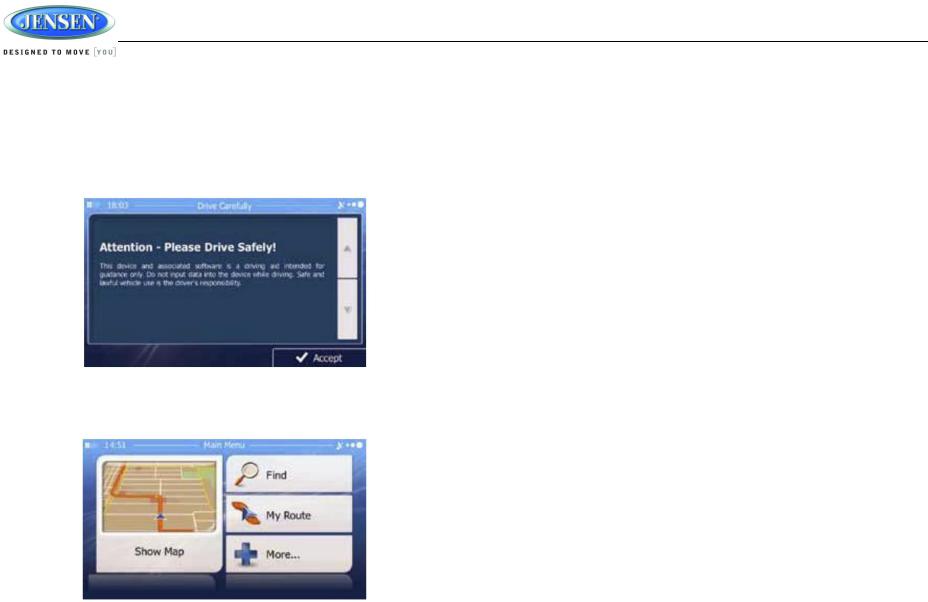
The Attention – Please Drive Safely! Screen is displayed each time the iGo primo software is turned ON as a reminder to make use of the systems navigational aids in a safe manner.
Before using the software, read this entire manual. Make sure that you are familiar with the system’s features and know how to operate the system. Proper use of the iGo primo software includes the following guidelines:
The iGo primo software is not a substitute for your personal judgment. The route suggestions should not supersede any local traffic regulation or your personal judgment and/or knowledge of safe diving practices. Prior to completing any maneuvers suggested by your iGo primo software (for example, a U-turn or a left turn), verify that you can legally and safely complete the maneuver. Do not follow route suggestions if they direct you to perform an unsafe or illegal maneuver, would place you in an unsafe situation, or would route you into an area that you would consider unsafe.
Glance at the screen only when necessary and safe to do so. Let the computer voice guide you. If prolonged viewing is necessary, pull of the road to a safe location.
Do not use the iGo primo software to locate emergency services (such as police, fire stations, hospitals, and clinics). The database may not include all emergency service providers. Use your own best judgment and ask for directions in these situations.
If the vehicle is in motion, only a passenger should program the iGo primo software. The driver should not program the system unless the vehicle is parked in a safe location.
The iGo primo software’s map database provides information on suggested routes without regard to factors that may affect your driving experience or the time required to arrive at your destination. For example, the system does not reflect road detours, closures, or construction, some road characteristics (e.g., road surface, slope or grade, weight or height restrictions, etc.), temporary traffic congestion, weather conditions, and similar factors.
iGo primo software provides turn-by-turn visual and voice assistance to direct you to your selected destination. The software quickly calculates step-by-step directions to any destination available on the included navigation map.
The iGo primo software uses Global Positioning System (GPS) satellites, and a digital roadway
Vehicle Position
The iGo promo software’s computer considers vehicle speed and heading changes, together with longitude and latitude information, to accurately determine vehicle heading and position on a digital map.
Signals from GPS satellites are used to determine the vehicle location. Three (good) or four (best) satellites must be received to accurately determine location. The GPS reception status is indicated by the GPS symbol on the map.
Map and Information Database
The map database used by your iGo promo software was created using high-resolution aerial and land based data collection.
Car navigation maps are frequently updated. While the database was judged to be as accurate as possible at the time of its release, a map database can never be 100% accurate. Road information that is maintained in the map databases, such as turn restrictions or road names may change over time.
4
JRV215N
SAFETY INFORMATION
User Agreement
When the unit is first turned on, you will see the following message, warning you to operate your navigation system appropriately:
You must agree to the above notice before using the navigation software. Tap the Accept button to proceed to the Navigation Menu.
Driver Safety Rules
The following safety rules must be followed to prevent accidents that can result in injury or death to yourself or others:
The driver should operate the device only when the vehicle is stopped. Only a vehicle passenger should operate the device while the vehicle is moving. When diving, the need to view the display is minimal. Voice prompts will guide you to your destinations
It is your responsibility to comply with all traffic laws.
The navigation software is designed to assist you in the process of reaching your destination. It is not a substitute for attentiveness and good judgment.
It is your responsibility to disregard any unsafe, hazardous, or illegal route suggestions.
The device does not include, analyze, process, consider, or reflect any of the following:
a.Legal restrictions (such as vehicular type, weight, height, width, load, and speed restrictions.
b.Road slope or grade, bridge height, width, weight, or other limits;
c.Population density;
d.Neighborhood quality or safety;
e.Availability or proximity of law enforcement, emergency rescue, medical, or other assistance;
f.Construction work zones or hazards;
g.Road or lane closures;
h.Road, traffic, or traffic facilities’ safety or condition;
i.Weather conditions;
j.Pavement characteristics or conditions;
k.Special events;
l.Traffic congestion.
While ever attempt is made to ensure that the database is accurate, roadways, points of interest, and business and service locations may change over time.
Do not use the unit to navigate to a police station, hospital, etc. in an emergency. Call 911 for assistance.
Laws in some states prohibit wearing stereo headphones or may prohibit use or placement of a navigation device while operation a motor vehicle. Please contact your state’s Department of Motor Vehicles for more information.
5
JRV215N
DISC NOTES
Depending on the recording status, conditions of the disc, and the equipment used for recording, some CD-Rs/CD-RWs may not play on this unit. For more reliable playback, please adhere to the following recommendations:
Use CD-RWs with speed 1x to 4x and write with speed 1x to 2x.
Use CD-Rs with speed 1x to 8x and write with speed 1x to 2x.
Do not play a CD-RW which has been written more than 5 times.
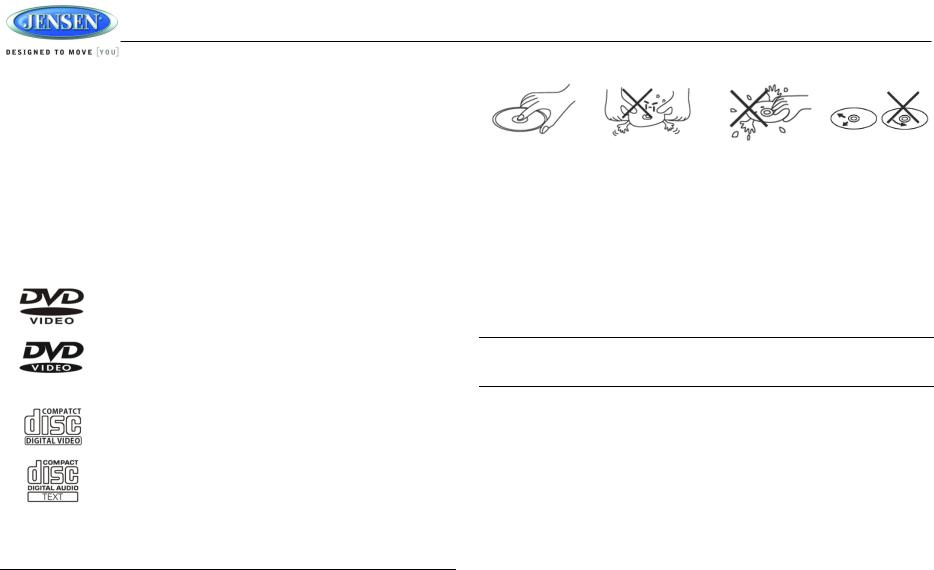
Compatible Disc Types
Table 1: General Disc Information
|
Symbol |
12cm Disc Properties |
Max Play time |
|
|
|
|
|
|
|
(MPEG 2 Method) |
|
|
Single side single layer (DVD-5) |
133 minutes |
|
|
Single side double layer (DVD-9) |
242 minutes |
|
|
Double side single layer (DVD-10) |
266 minutes |
|
|
Double side double layer (DVD-18) |
484 minutes |
|
|
|
|
|
|
Single side single layer (VCD) |
MPEG 1 Method |
|
|
|
74 minutes |
|
|
|
|
|
|
Single side single layer |
74 minutes |
|
|
|
|
|
|
|
|
NOTE: CD-R and CD-RW discs will not play unless the recording session is closed and the CD is finalized.
Disc Maintenance
A dirty or defective disc may cause sound dropouts while playing. Before playing, wipe the disc using a clean cloth, working from the center hole towards the outside edge. Never use benzene, thinners, cleaning fluids, anti-static liquids or any other solvent.
|
|
|
|
Insert label side up, |
Do not bend. |
Never touch the |
Wipe clean from this |
|
|
underside of the disc |
center to the edge. |
Be sure to use only round CDs for this unit and do not use any special shape CDs. Use of special shape CDs may cause the unit to malfunction.
Do not stick paper or tape on the disc. Do not use CDs with labels or stickers attached or that have sticky residue from removed stickers.
Do not expose discs to direct sunlight or heat sources such as hot air-ducts, or leave them in a vehicle parked in direct sunlight where there can be a considerable rise in temperature inside the vehicle.
NOTE: A disc may become scratched (although not enough to make it unusable) depending on how you handle it and other conditions in the usage environment. These scratches are not an indication of a problem with the player.
6

INSTALLATION
Before you Begin
JRV215N
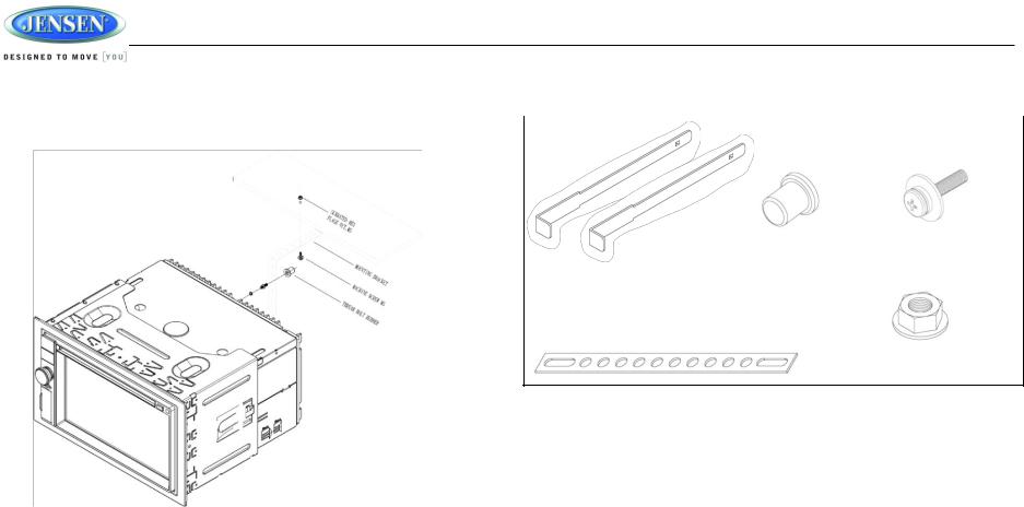
3.Locate the series of bend tabs along the top, bottom and sides of the mounting sleeve.
1.Disconnect Battery
Before you begin, always disconnect the battery negative terminal.
2.Remove Transport Screws and discard.
Important Notes
Before final installation, test the wiring connections to make sure the unit is connected properly and the system works.
Use only the parts included with the unit to ensure proper installation. The use of unauthorized parts can cause malfunctions.
Consult with your nearest dealer if installation requires the drilling of holes or other modifications to your vehicle.
Install the unit where it does not interfere with driving and cannot injure passengers if there is a sudden or emergency stop.
If the installation angle exceeds 30º from horizontal, the unit might not give optimum performance.
Avoid installing the unit where it will be subject to high temperatures from direct sunlight, hot air, or from a heater, or where it would be subject to excessive dust, dirt or vibration.
2-DIN Front Mount
With the sleeve fully inserted into the dashboard opening, bend as many of the tabs outward as necessary to firmly secure the sleeve to the dashboard.
4.Place the radio in front of the dashboard opening so the wiring can be brought through the mounting sleeve.
This unit can be installed in a dashboard with an opening of the following dimensions:
1.Slide the mounting sleeve off of the chassis if it has not already been removed. If it is locked into position, use the removal keys (supplied) to disengage it. Insert the keys through the holes in the front panel as far as they will go, and then slide the sleeve off the back of the unit.
2.Check the dashboard opening size by sliding the mounting sleeve into it. If the opening is not large enough, carefully cut or file as necessary until the sleeve easily slides into the opening. Do not force the sleeve into the opening or cause it to bend or bow. Check that there will be sufficient space behind the dashboard for the radio chassis.
5.Follow the wiring diagram carefully and make certain all connections are secure and insulated with crimp connectors or electrical tape to ensure proper operation.
6.After completing the wiring connections, reconnect battery and turn the unit on to confirm operation (vehicle ignition switch must be on). If the unit does not operate, recheck all wiring until the problem is corrected. Once proper operation is achieved, turn the ignition switch off and proceed with final mounting of the chassis.
7.Carefully slide the radio into the mounting sleeve making sure it is right-side-up until it is fully seated and the spring clips lock it into place.
8.Attach one end of the perforated support strap (supplied) to the screw stud on the rear of the chassis using the hex nut provided. Fasten the other end of the perforated strap to a secure part of the dashboard either above or below the radio using the screw and plain washer provided. Bend the strap, as necessary, to position it. Some vehicle installations provide cavity for rear support. In these applications, place the rubber bushing over the screw stud and insert the radio.
7
JRV215N
CAUTION: The perforated rear support strap or rear rubber mounting bushing |
Hardware Kit Contents |
|
|
must be used in the installation of the radio. Installation without either may result |
|
in damage to the radio or the mounting surface and void the manufacturer’s |
|
warranty. |
|
Thread Bolt Rubber |
Machine Screw M5 |
Key, EGI, T=1.00 (x2)
Mounting Bracket
Serrated Hex Flange Nut, M5
Reconnect Battery
When wiring is completed, reconnect the battery negative terminal.
9.Test radio operation by referring to the operating instructions for the unit.
Removing the unit
To remove the radio after installation:
1.Make sure the ignition is turned off, and then disconnect the cable from the vehicle’s battery negative (-) terminal.
2.Insert the removal keys straight into the holes on the front of the unit, as far as they will go.
3.Pull the radio straight out.
8

WIRING
|
|
|
|
JRV215N |
|
|
|
|
|
|
|
|
|
|
31300152 |
|
|
|
|
|
SHOWN ON PIN VIEW |
|
|
|
|
PIN NO. |
|
DESCRIPTION |
|
|
|
1 |
|
GROUND |
|
|
|
2 |
|
ILLUM (PARKING LIGHT) |
|
|
|
3 |
|
P.CNTR |
|
|
|
4 |
|
AMP REMOTE |
|
|
|
5 |
|
RIGHT REAR SPEARKER (+) |
|
|
|
6 |
|
RIGHT REAR SPEARKER (-) |
|
|
|
7 |
|
LEFT REAR SPEARKER (+) |
|
|
|
8 |
|
LEFT REAR SPEARKER (-) |
|
|
|
9 |
|
LEFT FRONT SPEAKER (-) |
|
|
|
10 |
|
LEFT FRONT SPEAKER (+) |
|
|
|
11 |
|
RIGHT FRONT SPEAKER (-) |
|
|
|
12 |
|
RIGHT FRONT SPEAKER (+) |
|
|
|
13 |
|
NC |
|
|
|
14 |
|
PARKING BRAKE |
|
|
|
15 |
|
+12V ACC SWITCHED |
|
|
|
16 |
|
+12V BATTERY |
|
|
|
|
|
|
|
WARNING!
Do not connect the +12VDC ACC SWITCHED wire to the battery. This wire MUST be connected to the Accessory/Ignition wire or a +12 volts switched power source.
WARNING!
Do not connect the ILLUM wire to the dimmer. This wire MUST be connected to a parking light circuit that provides +12VDC when parking lights are active.
9
JRV215N
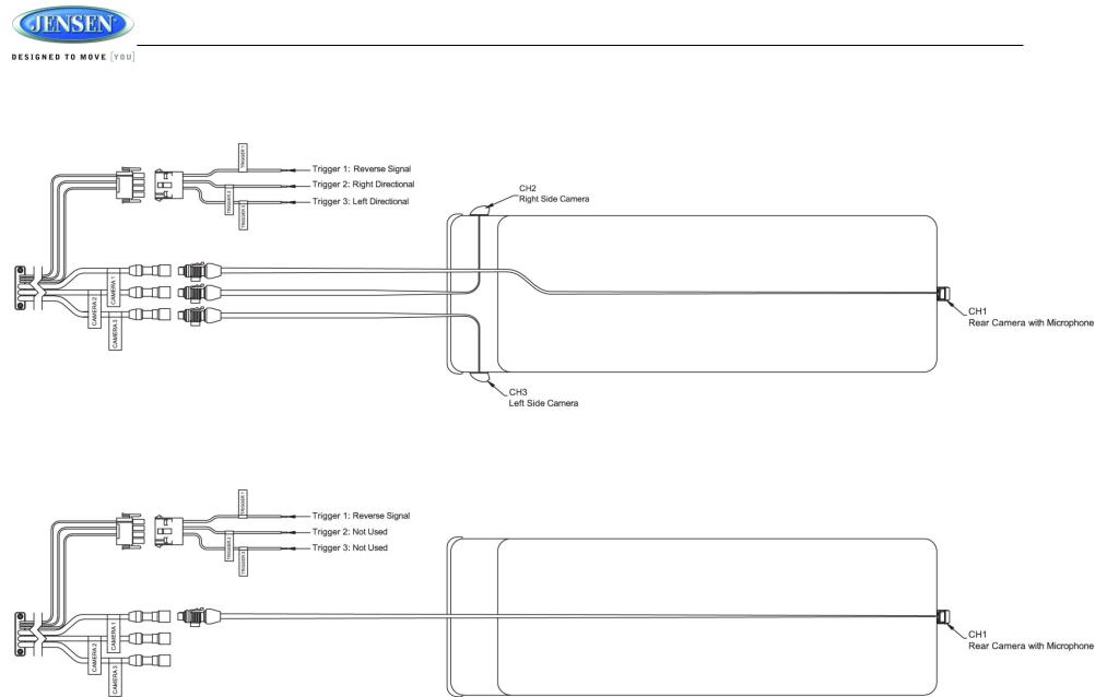
Recommended Camera Installation Configurations
3 Cameras Setup
1 Rear Camera Setup
10
JRV215N
BASIC OPERATION
Power On/Off
Press the power VOL knob (3) to turn the unit on. The unit will resume at the last mode (Tuner, Aux, etc.). Press and hold the VOL knob to turn the unit off. While ON, press the knob to activate the MUTE function.
Volume Control
To increase the volume, rotate the power VOL knob (3) clockwise.
To decrease the volume, rotate the power VOL knob counter-clockwise.
During adjustment, the volume level is displayed in the middle of the display as a horizontal bar graph with the associated number level setting from 0 (full mute) to 30 (0dB, no attenuation).
The screen will display the volume indicator bar for 5 seconds and then revert to the previous mode information.
Reset
Use a ball point pen or thin metal object to press the RESET button (4). The reset button should be activated for the following reasons:
initial installation of the unit when all wiring is completed
function buttons do not operate
error symbol on the display
Mute
Press the power VOL knob (3) to mute the audio output. “  ” will appear on the display.
Press the power VOL knob again to restore the audio output to the previous level.
Menu
Press the MENU button (1) or touch the home icon on-screen in the home menu to access different modes (Cameras, Navigation, AM/FM, Disc, Bluetooth, USB, SiriusXM, Weather, AUX 1, AUX 2, Zone2, Settings, Panel off and Dimming). Press and hold MENU to toggle between day and night dimmer settings when dimming control is turned off in settings.
Swipe from right to left, or touch the 2nd dot at the bottom of the screen to go to page 2. Swipe from left to right, or touch the 1st dot at the bottom of the screen to return to page 1.
Touch the on-screen button to adjust the settings under the specific mode.
11
|
|
|
|
JRV215N |
||
|
|
|
|
|
||
Navigation |
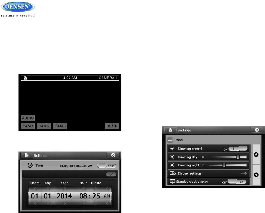
The current date and time is displayed on the bottom of the LCD display (9).To adjust the clock: |
|||||
1. |
Touch the “Settings” > “Time” > “Time setting” option on-screen (9). |
|||||
|
|
|
||||
|
|
|
2. |
Swipe the on-screen button on the top right to select between 12-hour clock and 24-hour |
||
Press the NAV button (2) or touch the on-screen button (9) in the home menu to access |
|
clock. |
||||
|
navigation mode. Press NAV to toggle between current audio mode and navigation. |
3. |
Use the on-screen arrows to adjust the Month, Day, Year, Hour, Minute and AM/PM (only |
|||
For more details, please refer to the separated navigation manual. |
|
when using a 12-hour clock). |
||||
Camera |
4. |
Touch when finished. |
||||
|
Touch the “Cameras” option on-screen (9) to access camera mode. |
Auxiliary Input |
||||
|
|
|
||||
|
Under camera mode, touch the screen to access camera 1, camera 2, and camera 3 and |
To access an auxiliary device: |
||||
|
|
|
||||
|
to enable/disable rear camera audio. |
1. |
Connect an audio source to the AUX IN connector on the front panel (7) or to the AUX IN |
|||
|
|
|
||||
|
|
|
|
cables on the back of the radio. Video input is accessible for both the “AUX 1” and “AUX 2” |
||
|
|
|
|
mode through the VIDEO IN cable at the back of the unit. |
||
|
|
|
2. |
Touch the “AUX 1” (front AUX) or “AUX 2” (rear AUX) on-screen button to select front or |
||
|
|
|
|
rear auxiliary input. |
||
|
|
|
3. |
Connect the audio source with a 3.5mm video cable at the jack (7), the radio will |
||
automatically switch to AUX 1 mode.
Remote Sensor
Point the remote control handset (sold separately) at the remote sensor IR (10) and press the function keys on the handset to control the system.
To view or adjust the camera setup options, go to the “Settings” under the home menu. See “Camera Sub-menu” on page 10.
Adjusting the Clock
Dimming/Display
1. Touch the “Dimming” option on-screen (9) to adjust the dimming levels for day and night viewing of the display, display settings and standby clock display ON/OFF.
2. Swipe the on-screen button to turn ON/OFF automatic dimming control (this requires
12
 Loading...