


DV2007
CD / MP3 / WMA/ DVD PLAYER / RECEIVER
Installation and Operation Manual
B |
|
|
A |
|
N |
|
D |
REL |
|
|
E |
T |
|
MU |
|
EN |
U |
M |
M
M
O
D
E
DVD PLAYER / RECEIVER |
DV2007 |
 DVD MENU
1. SAFETY INFORMATION
When Driving
Keep the volume level Iow enough to be aware of the road and traffic conditions.
When Car Washing
Do not expose the product to water or excessive moisture. This could cause electrical shorts, fire or other damage.
When Parked
Parking in direct sunlight can produce very high temperatures inside your vehicle. Give the interior a chance to cool down before starting playback.
Use the Proper Power Supply
This product is designed to operate with a 12 volt DC, negative ground battery system (the regular system in a North American car).
Protect the Disc Mechanism
Avoid inserting any foreign objects into the slot of this player. Failure to follow this may cause malfunction or permanent damage due to the precise mechanism of this unit.
CAUTION:
THIS MOBILE DVD PLAYER IS A CLASS I LASER PRODUCT. THIS UNIT USES A VISIBLE/INVISIBLE LASER BEAM WHICH COULD CAUSE HAZARDOUS RADIATION IF EXPOSED DIRECTLY . BE SURE TO OPERATE THE MOBILE DVD PLAYER CORRECTLY AS INSTRUCTED.
USE OF CONTROLS OR ADJUSTMENTS OR PERFORMANCE OR PROCEDURES OTHER THAN THOSE SPECIFIED HEREIN MAY RESULT IN HAZARDOUS RADIATION EXPOSURE.
DO NOT OPEN COVERS AND DO NOT REPAIR BY YOURSELF PLEASE REFER SERVICING TO A QUALIFIED TECHNICIAN.
WARNING:
TO REDUCE THE RISK OF FIRE OR ELECTRIC SHOCK, DO NOT EXPOSE THIS EQUIPMENT TO RAIN OR MOISTURE.
TO REDUCE THE RISK OF FIRE OR ELECTRIC SHOCK, AND ANNOYING INTERFERENCE, USE ONLY THE RECOMMENDED ACCESSORIES.
THIS DEVICE IS INTENDED FOR CONTINUOUS OPERATION.
This product incorporates copyright protection technology that is protected by method claims of certain U.S. Patents and other intellectual property rights owned by Macrovision Corporation and other rights owners. Use of this copyright protection technology must be authorized by Macrovision Corporation, and is intended for home and other limited viewing uses only unless otherwise authorized by Macrovision Corporation. Reverse engineering or disassembly is prohibited.
DV2007
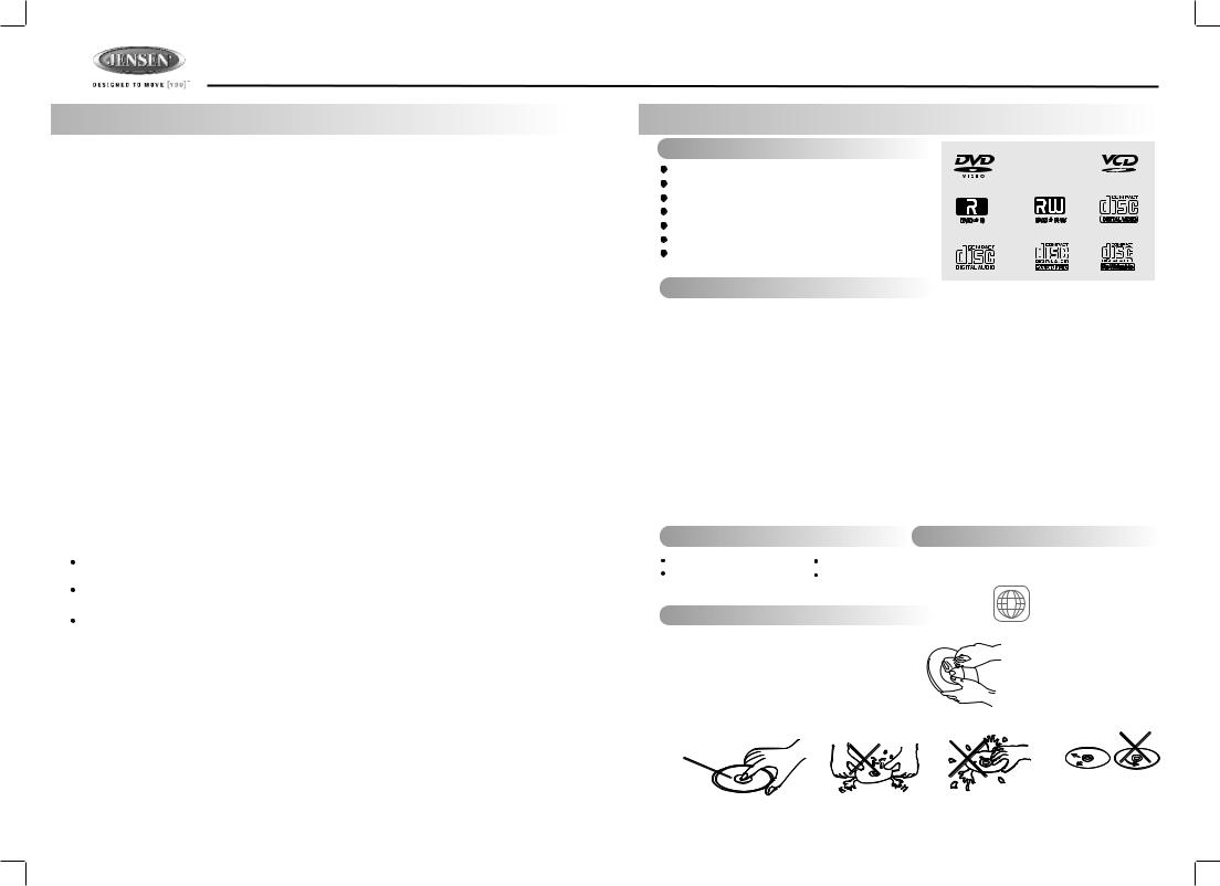
2. DISC AND FORMAT SUPPORTS
A. DISCS CAN PLAY WITH THIS UNIT
Digital Versatile Discs (DVDs)
Video CDs (VCDs)
Digital Versatile Discs Recordable(DVD+/-R)
Digital Versatile Discs Rewritable(DVD+/-RW)
Compact Discs (CDs)
CD Recordable (CD-R)
CD Rewritable (CD-RW)
B. FORMAT CAN PLAY WITH THIS UNIT
 AUDIO FORMAT
Playback CD-DA and MP3 or WMA digital music file on CD-ROM or DVD-ROM or USB or
Memory Card.
Note of MP3 and WMA:
Support Maximum 2000 files
Maximum 30 characters display
Supported Sampling frequencies; 32kHz, 44.1kHz, 48kHz.
Supported Bit-Rates: 32-256 kbps variable bit rate
 VIDEO FORMAT
Playback IMAGE JPEG, DVD Video, MPEG4. on CD-ROM or DVD-ROM or USB or Memory Card.
Noted of MPEG4
Supported decoding MPEG-4 video defined by ISO 14496-2 Standard
a.Simple Profile (SP) and
b.Advance Simple Profile (ASP)
Supported file format: .mp4 and .m4a (audio only)
C. DISCS WHICH CAN NOT BE PLAYED |
D. NOTE ON REGION CODE |
||
8 cm disc |
LD |
DVD players and DVD Video discs have their |
|
own Region Code numbers. This unit can |
|||
CDV, CDI, CDG, |
DVD RAM |
||
play the disc of all region code numbers. |
|||
ALL
E. DISC MAINTENANCE
Before playing, wipe the disc using a clean cloth, working from the center hole towards the outside edge. 
Never use benzene, thinners, cleaning fluids or anti-static liquids or any other solvent.
Note: A disc may become somewhat scratched (although not enough to make it unusable) depending on you handle it and conditions in the usage environment. Note these scratches are not an indication of any problem with the player.
Label side
Up
Do not bend |
Never touch |
Wipe the disc surface |
the under side |
from the |
|
|
of a disc |
center to the edge. |
2
DV2007
3. INSTALLATION
Before You Begin
1.Disconnect Battery
Before you begin, always disconnect the battery negative terminal.
2.Remove Transport Screws
Important Notes
•Before final installation, test the wiring connections to make sure the unit is connected properly and the system works.
•Use only the parts included with the unit to ensure proper installation. The use of unauthorized parts can cause malfunctions.
•Consult with your nearest dealer if installation requires the drilling of holes or other modifications to your vehicle.
•Install the unit where it does not interfere with driving and cannot injure passengers if there is a sudden or emergency stop.
•If the installation angle exceeds 30º from horizontal, the unit might not give optimum performance.
•Avoid installing the unit where it will be subject to high temperatures from direct sunlight, hot air, or from a heater, or where it would be subject to excessive dust, dirt or vibration.
•Be sure to remove the control panel before installing the unit.
DIN Front/Rear Mount
This unit can be property installed with either a “Front” (conventional DIN front mount) or “Rear” (DIN rear mount installation, utilizing threaded screw holes at the sides of the unit chassis) mount. For details, refer to installation methods A and B.
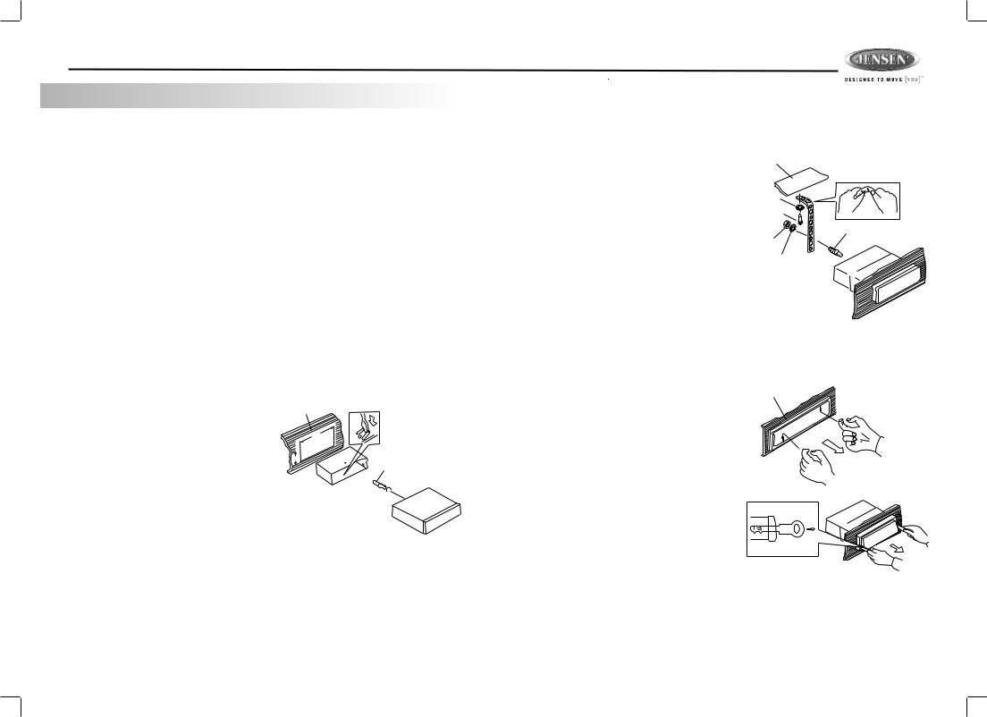
DIN Front Mount (Method A)
1. Remove the detachable front panel, if it is Dashboard attached to the chassis, by pushing the
REL button.
182
2.Slide the mounting sleeve off of the chassis if it has not already been removed.
53
If it is locked into position, use the removal keys (supplied) to disengage it. The removal keys are depicted on page 4.
3.Check the dashboard opening size by sliding the mounting sleeve into it. If the opening is not large enough, carefully cut or file as necessary until the sleeve easily
slides into the opening. Do not force the sleeve into the opening or cause it to bend or bow. Check that there will be sufficient space behind the dashboard for the radio chassis.
4.Locate the series of bend tabs along the top, bottom and sides of the mounting sleeve. With the sleeve fully inserted into the dashboard opening, bend as many of the tabs outward as necessary to firmly secure the sleeve to the dashboard.
5.Place the radio in front of the dashboard opening so the wiring can be brought through the mounting sleeve.
6.Follow the wiring diagram carefully and make certain all connections are secure and insulated with crimp connectors or electrical tape to ensure proper operation.
7.After completing the wiring connections, attach the front panel and turn the unit on to confirm operation (vehicle ignition switch must be on). If the unit does not operate,
recheck all wiring until the problem is corrected. Once proper operation is achieved, turn the ignition switch off and proceed with final mounting of the chassis.
8.Carefully slide the radio into the mounting sleeve making sure it is right-side-up until it is fully seated and the spring clips lock it into place.
9.Attach one end of the
perforated support strap |
Dashboard |
|
(supplied) to the screw stud on |
Support Strap |
|
the rear of the chassis using |
||
|
||
the hex nut and spring washer |
Plain Washer |
|
provided. Fasten the other end |
||
Screw (4 x 12mm) |
||
of the perforated strap to a |
||
|
||
secure part of the dashboard |
Screw Stud |
|
either above or below the radio |
Hex Nut (5mm) |
|
using the screw and plain |
Spring Washer |
|
washer provided. Bend the |
|
|
strap, as necessary, to position |
|
|
it. CAUTION: The rear of the |
|
|
radio must be supported with |
|
the strap to prevent damage to the dashboard from the weight
of the radio or improper operation due to vibration.
10.Re-attach the front panel to the chassis and test radio operation by referring to the operating instructions for the unit.
Removing the Unit
To remove the radio after installation:
1.Insert fingers into the groove in the front of frame and pull out to remove the frame. (When re-attaching the frame, point the side with a groove downwards and reattach.)
2.Insert the removal keys straight back until they click, and then pull the radio out. If removal keys are inserted at an angle, they will not lock properly to release the unit.
Trim Plate Installation
Dashboard
Removal Key
Push the trim plate against the chassis until it is fitted. You must do this before you install the
control panel, otherwise it can't be attached.
DIN Rear Mount (Method B)
This unit has threaded holes in the chassis side panels which may be used with the original factory mounting brackets of some vehicles to mount the radio to the dashboard. Please consult with your local mobile stereo shop for assistance on this type of installation.
1.Remove the existing factory radio from the dashboard or center console mounting. Save all hardware and brackets as they will be used to mount the new radio.
2.Carefully unsnap the plastic trim ring from the front of the new radio chassis. Remove and
3 |
discard the trim ring. |
DV2007
3.Remove the factory mounting brackets and hardware from the existing radio and attach them to the new radio. Select a position where the screw
holes of the bracket and the |
Screws |
|
|
||
screw holes of the main unit |
Dashboard |
|
are aligned (are fitted). |
||
|
||
Tighten the screws at 2 |
|
|
places on each side. Do not |
Factory |
|
exceed M5 x 9 MM maximum |
||
Mounting |
||
screw size. Longer screws |
||
Bracket |
may damage components
Hook (Remove)
inside the chassis.
4.Wire the new radio to the
vehicle as outlined in the Universal Installation instructions.
5.Mount the new radio assembly to the dashboard or center console using the reverse procedure of step 1.
NOTE: The mounting box, outer trim ring, and half-sleeve are not used for method B installation.
Reconnect Battery
When wiring is complete, reconnect the battery negative terminal.
Detachable Control Panel (DCP)
Removing the Detachable Control Panel (DCP)
1.Turn the power off.
2. Press the REL button.
3.Remove the DCP.
Attaching the DCP |
PANEL RELEASE |
BUTTON |
1.Attach the panel at the right side first, with point B on the main unit touching point A on the DCP (as shown in the
diagram). |
2 |
2.Press the left side of the DCP onto the main unit until a
“click” is heard. |
|
A |
CAUTION: |
1 |
B |
•DO NOT insert the DCP from the left side. Doing so may damage it.
•The DCP can easily be damaged if dropped or
subjected to a strong shock. When the release button is pressed and the DCP is unlocked, the vehicle's vibrations may cause it to fall. To prevent damage to the DCP, always store it in a protective case after detaching it.
•The rear connector that connects the main unit and the DCP is an extremely important part. Be careful not to damage it by pressing on it with fingernails, pens, screwdrivers, etc.
•If the DCP is dirty, remove debris with a soft, dry cloth only. You can use a cotton swab soaked in isopropyl alcohol to clean the socket on the back of the DCP.
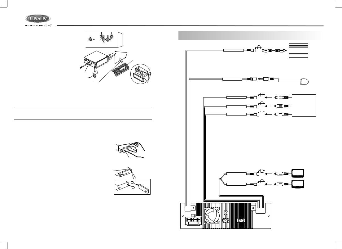
4. WIRING DIAGRAM-AUDIO/VIDEO CONNECTIONS
SUB-WOOFER OUTPUT BLUE |
SUB |
SUB-W OUT |
WOOFER
External Remote Receiver Not Included.
Sold Separately
EXTERNAL REMOTE JACK |
PINK |
EXTERNAL REMOTE |
|
REMOTE |
|
RECEIVER |
|
VIDEO INPUT |
YELLOW |
|
|
VIDEO IN |
|
|
|
AUDIO INPUT (RIGHT) |
RED |
VCR or DVD |
|
or |
|||
AUDIO IN R |
|
GAME CONSOLE
AUDIO INPUT (LEFT) WHITE

AUDIO IN L
VIDEO (1) OUTPUT |
YELLOW |
VIDEO OUT (1) |
|
VIDEO (2) OUTPUT |
YELLOW |
VIDEO OUT (2) |
|
FUSE |
4

DV2007
5. WIRING DIAGRAM - POWER / SPEAKERS (20 PIN)
|
|
cable |
|
FUSE |
ANTENNA |
(Not supplied) |
|
|
|
EXTENDER |
|||
|
|
ready |
WHITE |
|
|
ANTENNA |
cableremote |
|
20-PIN |
JACK |
CABLE |
||
BLACK |
iPod |
AUDIO/POWER |
|
|
||
|
|
|
|
|
||
|
|
|
|
HARNESS |
|
|
|
|
|
(See Figure 1 ) |
|
|
|
wired |
|
|
|
|
(Not supplied) |
|
|
|
|
|
|
|
|
|
iPod |
|
GREY |
|
WHITE |
|
|
|
RCA-TO-RCA |
|
|
|
|
|
|
|
|
|
|
|
|
|
|
|
|
|
|
|
|
|
|
|
|
||||||||||||||||||||||||||||||
|
|
|
|
|
|
CABLES |
|
|
|
|
|
|
|
|
|
|
|
|
|
|
|
|
|
|
|
|
|
|
|
|
|
|
|||||||||||||||||||||||||||||||
|
|
|
|
|
|
|
|
|
|
|
|
|
|
|
|
|
|
REAR |
|
|
|
|
L-CH |
|
|
|
|
|
|
|
|
|
|
|
|
|
|
|
|
|
|
|
|
|
|
|
|
|
|
|
|
|
|
|
|
|
|
|
|
|
|||
|
|
|
|
|
|
|
|
|
|
|
|
|
|
|
|
|
|
|
|
|
|
|
|
|
|
|
|
|
|
|
|
|
|
|
|
|
|
|
|
|
|
|
|
|
|
|
|
|
|
|
|
|
|
|
|
|
|
|
|||||
|
|
|
|
|
|
|
|
|
|
|
|
|
|
|
|
|
|
CHANNEL |
|
|
RED |
|
|
|
|
|
|
|
|
|
|
|
|
|
|
|
|
|
|
|
|
|
|
|
|
|
|
|
|
|
|
|
|
|
|
|
|
|
|||||
|
|
|
|
|
|
|
|
|
|
|
|
|
|
|
|
|
|
BLACK |
|
|
|
|
R-CH |
|
|
|
|
|
|
|
|
|
|
|
|
|
|
|
|
AMP |
|
|
|
|
|
|
|
|
|
|
|
||||||||||||
|
|
|
|
|
|
|
|
|
|
|
|
|
|
|
|
|
|
|
WHITE |
|
|
|
|
|
|
|
|
|
|
|
|
|
|
|
|
|
|
|
|
|
|
|
|
|
|||||||||||||||||||
WIRED |
|
FRONT |
|
|
|
|
|
L-CH |
|
|
|
|
|
|
|
|
|
|
|
|
|
|
|
|
|
|
|
|
|
|
|
|
|
||||||||||||||||||||||||||||||
|
|
|
|
|
|
|
|
|
|
|
|
|
|
|
|
|
|
|
|
|
|
|
|
|
|
|
|
|
|
||||||||||||||||||||||||||||||||||
|
CHANNEL |
|
|
|
|
RED |
|
|
|
|
|
|
|
|
|
|
|
|
|
|
|
|
|
|
|
|
|
|
|
|
|
|
|
|
|
|
|
|
|
|
|
|
|
||||||||||||||||||||
REMOTE |
|
|
|
|
|
|
|
|
|
-CH |
|
|
|
|
|
|
|
|
|
|
|
|
|
|
|
|
|
|
|
|
|
|
|
|
|
|
|
|
|
|
|
|
|
|
|
|
|
||||||||||||||||
|
|
|
|
|
|
|
|
|
|
|
|
|
|
|
|
|
|
|
|
|
|
|
|
|
|
|
|
|
|
|
|
|
|
|
|
|
|
|
|
|
|
|
|
|
|
||||||||||||||||||
|
|
|
|
|
|
|
|
|
|
|
|
|
|
|
|
|
|
BLUE |
|
|
|
R |
|
|
|
|
|
|
|
|
|
|
|
|
|
|
|
|
|
|
|
|
|
|
|
|
|
|
|
|
|
|
|
|
|
|
|
|
|
||||
|
|
|
|
|
|
|
|
|
|
|
|
|
|
|
|
|
|
|
|
|
|
|
|
|
|
|
|
|
|
|
|
|
|
|
|
|
|
|
|
|
|
|
|
|
|
|
|
|
|
|
|
|
|
|
|
|
|
|
|||||
|
|
|
|
|
|
|
|
|
|
|
|
|
|
|
|
|
|
POWER ANTENNA/ |
|
|
|
|
|
|
|
|
|
Power Antenna |
|
|
|
|
|
|
|
|
|
|
|
|
|
|
|
|
|
|
|
|
|
|
|||||||||||||
|
|
|
|
|
|
|
|
|
|
|
|
|
|
|
|
|
|
AMPLIFIER REMOTE |
|
|
|
|
|
|
|
|
|
|
|
|
|
|
|
|
|
|
|
|
|
|
|
|
|
|
|
|
|
|
|
||||||||||||||
|
|
|
|
|
|
|
|
|
|
|
|
|
|
|
|
|
|
|
|
|
|
|
|
|
|
|
|
|
|
|
Connect to power antenna or amplifier, |
|
|
|
|
|
|
||||||||||||||||||||||||||
|
|
|
|
|
|
|
|
|
|
|
|
|
|
|
|
|
|
BLACK |
|
|
|
|
|
|
|
|
If not used, Tape bare end of wire. |
|
|
|
|
|
|
|
|||||||||||||||||||||||||||||
|
|
|
|
|
|
|
|
|
|
|
|
|
|
|
|
|
|
|
|
|
|
|
|
|
|
|
|
|
|
|
|
|
|
|
|
|
|
|
|
|
|
|
|
|
|
|
|
|
|
|
|
|
|
|
|
|
|
|
|||||
|
|
|
|
|
|
|
|
|
|
|
|
|
|
|
|
|
|
GROUND |
|
|
|
|
|
|
|
|
|
Ground |
|
|
|
|
|
|
|
|
|
|
|
|
|
|
|
|
|
|
|
|
|
|
|
|
|
|
|||||||||
|
|
|
|
|
|
|
|
|
|
|
|
|
|
|
|
|
|
|
|
|
|
|
|
|
|
|
|
|
|
|
Connect to ground terminal or clean |
|
|
|
|
|
|
|
|||||||||||||||||||||||||
|
|
|
|
|
|
|
|
|
|
|
|
|
|
|
|
|
|
YELLOW |
|
|
|
|
|
|
|
|
unpainted metal part of chassis. |
|
|
|
|
|
|
|
|
|
|
||||||||||||||||||||||||||
|
|
|
|
|
|
|
|
|
|
|
|
|
|
|
|
|
|
|
|
|
|
|
|
|
|
Memory / Battery |
|
|
|
|
|
|
|
|
|
|
|
|
|
|
|
|
|
|
|
||||||||||||||||||
|
|
|
|
|
|
|
|
|
|
|
|
|
|
|
|
|
|
+12 VOLTS |
|
|
|
|
|
|
|
|
|
|
|
|
|
|
|
|
|
|
|
|
|
|
|
|
|
|
|
|
|||||||||||||||||
|
|
|
|
|
|
|
|
|
|
|
|
|
|
|
|
|
|
CONSTANT |
|
|
|
|
|
|
|
|
|
Connect to battery or 12 volt power source |
|
|
|
||||||||||||||||||||||||||||||||
|
|
|
|
|
|
|
|
|
|
|
|
|
|
|
|
|
|
|
|
|
|
|
|
|
|
|
|
|
|
|
that is always live. The radio will not work if |
|
|
|
|||||||||||||||||||||||||||||
|
|
|
|
|
|
|
|
|
|
|
|
|
|
|
|
|
|
RED |
|
|
|
|
|
|
|
|
this wire is not connected. |
|
|
|
|
|
|
|
|
|
|
|
|||||||||||||||||||||||||
|
|
|
|
|
|
|
|
|
|
|
|
|
|
|
|
|
|
|
|
|
|
|
|
|
|
|
|
|
|
|
|
|
|
|
|
|
|
|
|
|
|
|
|
|
|
|
|
|
|
|
|
|
|
|
|
|
|
|
|||||
|
|
|
|
|
|
|
|
|
|
|
|
|
|
|
|
|
|
+12 VOLTS |
|
|
|
|
|
|
|
|
|
Accessory / Ignition |
|
|
|
|
|
|
|
|
|
|
|
||||||||||||||||||||||||
|
|
|
|
|
|
|
|
|
|
|
|
|
|
|
|
|
|
SWITCHED |
|
|
|
|
|
|
|
|
|
|
|
|
|
|
|
|
|
|
|
|
|||||||||||||||||||||||||
|
|
|
|
|
|
|
|
|
|
|
|
|
|
|
|
|
|
|
|
|
|
|
|
|
|
|
Connect to existing radio wire or radio fuse. |
|
|
|
|||||||||||||||||||||||||||||||||
|
|
|
|
|
|
|
|
|
|
|
|
|
|
|
|
|
|
|
|
|
|
|
|
|
|
|
|
|
|
|
|
|
|
||||||||||||||||||||||||||||||
|
|
|
|
|
|
|
|
|
|
|
|
|
|
|
|
|
|
|
|
|
|
|
|
|
|
|
|
|
|
|
|
|
|
|
|
|
|
|
|
|
|
|
|
|
|
|
|
|
|
|
|
|
|
|
|
|
|
|
|
|
|
|
|
|
|
|
|
|
|
|
|
|
|
|
|
|
|
|
|
|
|
|
|
|
|
|
|
|
|
|
|
|
|
|
1 |
|
2 |
3 |
4 |
5 |
|
|
|
6 |
7 |
8 |
|
9 |
10 |
|
|
|
|||||||||||||||
|
|
|
|
|
|
|
|
|
|
|
|
|
|
|
|
|
|
|
|
|
|
|
|
|
|
|
|
|
|
|
|
|
|
|
|
|
|
|
|
|
|
|
|
|
|
|
|
|
|
|
|
|
|
|
|
|
|
|
|
|
|
|
|
|
|
|
|
|
|
|
|
|
|
|
|
|
|
|
|
|
|
|
|
|
|
|
|
|
|
|
|
|
|
|
|
|
|
|
|
|
|
|
|
|
|
|
|
|
|
|
|
|
|
|
|
|
|
|
|
|
|
|
|
|
|
|
|
|
|
|
|
|
|
|
|
|
|
|
|
|
|
|
|
|
|
|
|
|
|
|
|
|
|
|
Pin View |
|
11 |
|
12 |
13 |
14 |
15 |
|
|
|
16 |
17 |
18 |
|
19 |
20 |
|
Figure 1 |
||||||||||||||||||
|
|
|
|
|
|
|
|
|
|
|
|
|
|
|
|
|
|
|
|
|
|
|
|
|
|
|
|
|
|
|
|
|
|
|
|
|
|
|
|
|
|
|
|
|
|
|
|
|
|
|
|
|
|
|
|
|
|
|
|||||
|
|
|
|
|
|
|
|
|
|
|
|
|
|
|
|
|
|
|
|
|
|
|
|
|
|
|
|
|
|
20 PIN AUDIO / POWER HARNESS |
|||||||||||||||||||||||||||||||||
|
|
|
|
|
|
|
|
|
|
|
|
|
|
|
|
|
|
|
|
|
|
|
|
|
|
|
|
|
|
|
|
|
|
|
|
|
|
20 PIN HARNESS PIN CHART |
|
|
|
|
|
|
|
||||||||||||||||||
|
|
|
|
|
|
|
|
|
|
|
|
|
|
|
|
|
|
|
|
|
|
|
|
|
|
|
|
|
|
|
|
|
|
|
|
|
|
|
|
|
|
|
|
|
|
|
|
|
|
|
|
|
|
|
|
|
|
|
|
|
|
|
|
|
|
|
|
|
|
|
|
|
|
|
|
|
|
|
|
|
|
|
|
|
|
|
|
|
|
|
PIN |
|
WIRE COLOR |
|
|
|
|
|
|
|
|
|
|
|
FUNCTION / LABEL |
|
|||||||||||||||||||||
|
|
|
|
|
|
|
|
|
|
|
|
|
|
|
|
|
|
|
|
|
|
|
|
|
|
|
1 |
|
GREY / BLACK |
|
|
|
|
|
RIGHT FRONT SPEAKER ( |
) |
|
||||||||||||||||||||||||||
|
|
|
|
|
|
|
|
|
|
|
|
|
|
|
|
|
|
|
|
|
|
|
|
|
|
2 |
|
|
GREY |
|
|
|
|
|
|
|
|
|
RIGHT FRONT SPEAKER (+) |
|
|||||||||||||||||||||||
|
LEFT FRONT |
|
|
|
|
|
|
|
|
|
|
|
|
|
|
|
RIGHT FRONT |
|
|
|
3 |
|
|
VIOLET |
|
|
|
|
|
|
|
|
|
RIGHT REAR SPEAKER (+) |
|
||||||||||||||||||||||||||||
|
|
WHITE-BLACK LF |
|
|
|
|
|
|
|
|
|
|
|
|
|
|
|
GREY-BLACK RF |
|
|
|
4 |
|
|
VIOLET/BLACK |
|
|
|
|
|
RIGHT REAR SPEAKER ( |
) |
|
|
|||||||||||||||||||||||||||||
|
|
|
|
|
|
|
|
|
|
|
|
|
|
|
|
|
|
|
|
|
|
|
|
|
|
5 |
|
|
PINKEMPTY |
|
|
|
|
|
|
|
|
|
PARKINGN/A BRAKE ( |
) |
|
|
|
|
|
|
|||||||||||||||||
|
|
WHITE LF+ |
|
|
|
|
|
|
|
|
GREY RF+ |
|
|
|
|
6 |
|
|
GREEN |
|
|
|
|
|
|
|
|
|
LEFT REAR SPEAKER (+) |
|
|
|
|||||||||||||||||||||||||||||||
|
|
|
|
|
|
|
|
|
|
|
|
|
|
|
|
|
|
|
|
|
|
|
|
|
|
7 |
|
|
GREEN / BLACK |
|
|
|
|
|
LEFT REAR SPEAKER ( |
) |
|
|
|
||||||||||||||||||||||||
|
LEFT REAR |
|
|
|
|
|
|
|
|
RIGHT REAR |
|
|
|
|
8 |
|
|
RED |
|
|
|
|
|
|
|
|
|
IGNITION (ACC) |
|
|
|
|
|
|
|
||||||||||||||||||||||||||||
|
|
|
|
|
|
|
|
|
|
|
|
|
9 |
|
|
BLACK |
|
|
|
|
|
|
|
|
|
REAR PRE-AMPLIFIER LINE OUT COMMON |
|
||||||||||||||||||||||||||||||||||||
|
GREEN-BLACK LR |
|
|
|
|
|
|
|
VIOLET-BLACK RR |
|
|
|
|
|
|
|
|
|
|
|
|
|
|
|
|
|
|
|
|
|
|
|
|
|
|
|
|
|
|
|
|
|
|
|
|
|
|
|
|
|
|||||||||||||
|
|
|
|
|
|
|
|
|
|
|
|
10 |
|
RED |
|
|
|
|
|
|
|
|
|
RIGHT REAR PRE-AMPLIFIER LINE OUT |
|
||||||||||||||||||||||||||||||||||||||
|
|
|
|
|
|
|
|
|
|
|
|
|
|
|
|
|
|
|
|
|
|
|
|
|
|
|
|
|
|
|
|
|
|
|
|
|
|||||||||||||||||||||||||||
|
|
GREEN LR+ |
|
VIOLET RR+ |
|
|
|
11 |
|
WHITE |
|
|
|
|
|
|
|
|
|
LEFT FRONT SPEAKER (+) |
|
||||||||||||||||||||||||||||||||||||||||||
|
|
|
|
|
|
|
|
|
|
|
|
|
|
|
|
|
|
|
|
|
|
|
|
|
|
12 |
|
WHITE / BLACK |
|
|
|
|
|
LEFT FRONT SPEAKER ( |
) |
|
|
||||||||||||||||||||||||||
|
|
|
|
|
|
|
|
|
|
|
|
|
|
|
|
|
|
|
|
|
|
|
|
|
|
|
13 |
|
BLUE/WHITE |
|
|
|
|
|
POWER AMPLIFIER REMOTE (+) |
|
|||||||||||||||||||||||||||
|
|
|
|
|
|
|
|
|
|
|
|
|
|
|
|
|
|
|
|
|
|
|
|
|
|
|
14 |
|
BLUE |
|
|
|
|
|
|
|
|
|
POWER ANTENNA |
|
|
|
|
|
|
|
|||||||||||||||||
|
|
|
|
|
|
|
|
|
|
|
|
|
|
|
|
|
|
|
|
|
|
|
|
|
|
|
15 |
|
YELLOW |
|
|
|
|
|
|
|
|
|
BATTERY (+) |
|
|
|
|
|
|
|
|
|
|
||||||||||||||
|
|
|
|
|
|
|
|
|
|
|
|
|
|
|
|
|
|
|
|
|
|
|
|
|
|
|
16 |
|
BLACK |
|
|
|
|
|
|
|
|
|
CHASSIS GROUND |
|
|
|
|
|
|
||||||||||||||||||
|
|
|
|
|
|
|
|
|
|
|
|
|
|
|
|
|
|
|
|
|
|
|
|
|
|
|
17 |
|
WHITE |
|
|
|
|
|
|
|
|
|
LEFT FRONT PRE-AMPLIFIER LINE OUT |
|
|||||||||||||||||||||||
|
|
|
|
|
|
|
|
|
|
|
|
|
|
|
|
|
|
|
|
|
|
|
|
|
|
|
18 |
|
RED |
|
|
|
|
|
|
|
|
|
RIGHT FRONT PRE-AMPLIFIER LINE OUT |
|
|||||||||||||||||||||||
|
|
|
|
|
|
|
|
|
|
|
|
|
|
|
|
|
|
|
|
|
|
|
|
|
|
|
19 |
|
BLACK |
|
|
|
|
|
|
|
|
|
FRONT PRE-AMPLIFIER LINE OUT COMMON |
|
|||||||||||||||||||||||
|
|
|
|
|
|
|
|
|
|
|
|
|
|
|
|
|
|
|
|
|
|
|
|
|
|
|
20 |
|
WHITE |
|
|
|
|
|
|
|
|
|
LEFT REAR PRE-AMPLIFIER LINE OUT |
|
|||||||||||||||||||||||
6. CONTROL PANEL FUNCTION
3 |
7 |
19 |
22 |
2 |
|
|
BAND |
|
|
|
|
|
|
|
DVD PLAYER / RECEIVER |
DV2007 |
|
|
REL |
|
MENU |
|
|
|
|
M |
|
|
|
|
|
E |
|
|
|
|
T |
|
|
|
|
|
U |
|
M |
|
|
|
M |
|
|
|
|
|
|
|
OD |
DVD MENU |
|
|
|
|
E |
|
|
1 |
6 |
4 |
5 |
21 |
20 |
12 |
13 |
14 |
15 |
16 |
17 |
10 |
9 |
8 |
11 |
18 |
OPERATIONS:
|
SYSTEM |
TUNER |
CD/MP3/WMA |
DVD |
|
|
|
|
|||||
KEY |
Short |
|
Long |
Short |
Long |
Short |
Long |
Short |
|
Long |
Short |
|
Long |
|
|
|
|||||||||||
|
Press |
|
Press |
Press |
Press |
Press |
Press |
Press |
|
Press |
Press |
|
Press |
1 |
Mute |
|
Power |
|
|
|
|
|
|
|
|
|
|
2 |
Eject |
|
|
|
|
Eject |
|
Eject |
|
|
|
|
|
3 |
|
|
|
|
|
|
|
|
|
||||
Panel Release button |
Panel Release buttonPanel Release button |
Panel Release button |
|
|
|
||||||||
4 |
Audio |
|
|
|
|
Ok |
|
Ok |
|
Enter |
|
|
|
|
Menu |
|
|
|
|
|
|
|
|
|
|
|
|
5 |
Mode |
|
|
|
|
|
|
|
|
|
|
|
|
6 |
Encoder |
|
|
|
|
|
|
|
|
|
|
|
|
Volume |
|
|
|
|
|
|
|
|
|
|
|
|
|
|
|
|
|
|
|
|
|
|
|
iPod |
|
|
|
7 |
|
|
|
Band |
|
|
|
|
|
|
|
|
|
|
|
|
|
|
|
|
|
|
|
|
Search |
|
|
8Sub-W
9Lo/Dx
10 |
Ix-bass |
|
|
|
|
|
|
|
11 |
PS |
AS |
Set-up |
OSD |
Set-up |
iPod |
iPod |
|
infor mation |
Video |
|||||||
12 |
M1 |
Memor y 1 Pause/Play |
Pause/Play |
|
Pause/Play |
|
||
13 |
M2 |
Memor y 2 |
Stop |
Stop |
|
|
|
|
14 |
|
Memor y 3 |
Repeat Off |
Repeat Off |
|
Album |
||
M3 |
Repeat Track |
Repeat Chapter |
Repeat |
|||||
Repeat |
||||||||
|
|
|
Repeat Disc |
Repeat Title |
|
|
||
15 |
M4 |
Memor y 4 Random |
Short press M4 |
Shuffle |
Album |
|||
DVD Menu |
||||||||
|
|
|
Folder |
|
Shuffle |
|||
16 |
M5 |
Memor y 5 |
Down |
|
|
|
|
|
17 |
M6 |
Memor y 6 |
Up |
|
DVD Audio |
|
|
|
18Display
19Menu
|
20 |
Seek Up |
Tune Up |
File/Track |
Fast |
Next |
Fast |
File Up |
Fast |
|
|
|
|
Up |
Forward |
|
Forward |
|
Forward |
|
21 |
Seek |
Tune |
File/Track |
Fast |
Back |
Fast |
File Down |
Fast |
|
Down |
Down |
Down |
Backward |
Backward |
Backward |
|||
|
22 |
|
|
3.5mm A/V In Jack |
|
|
|
|
|
5
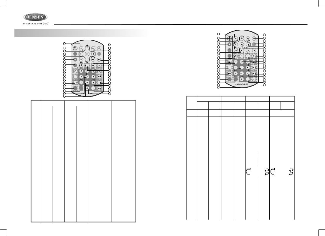
7. REMOTE FUNCTION
9 |
|
|
|
12 |
1 |
|
|
|
2 |
10 |
|
|
|
8 |
|
|
|
|
|
5 |
|
|
|
4 |
|
|
|
MODE |
|
|
|
|
|
|
15 |
|
|
|
11 |
|
VOLUME |
|
|
16 |
6 |
|
|
|
|
|
|
|
17 |
|
13 |
|
|
|
|
|
|
|
14 |
|
3 |
|
|
|
|
AUDIO |
|
|
18 |
|
30 |
|
|
||
|
|
|
37 |
|
|
|
|
|
|
34 |
|
|
|
31 |
|
|
|
|
|
19 |
|
|
|
38 |
20 |
|
|
|
21 |
35 |
GOTO |
|
|
39 |
22 |
|
|
|
24 |
32 |
|
|
|
36 |
25 |
|
MENU |
|
27 |
7 |
MUTE |
DISPLAY |
+10 |
33 |
|
|
|||
40 |
|
|
|
29 |
23 |
|
|
|
28 |
26 |
|
|
|
|
OPERATIONS:
KEY |
SYSTEM |
TUNER |
CD/MP3/WMA |
DVD |
|
|
||||
Short |
Long |
Short |
Long |
Short |
Long |
Short |
|
Long |
||
|
|
|||||||||
|
Press |
Press |
Press |
Press |
Press |
Press |
Press |
|
Press |
|
|
|
|
|
|
|
|
|
|
|
|
1 |
Power |
|
|
|
|
|
|
|
|
|
2 |
Eject |
|
|
|
Eject |
|
Eject |
|
|
|
|
|
|
|
|
|
|
|
|
|
|
3 |
Audio |
|
|
|
|
|
|
|
|
|
|
Menu |
|
|
|
|
|
|
|
|
|
4 |
Mode |
|
|
|
|
|
|
|
|
|
|
|
|
|
|
|
|
|
|
|
|
5 |
Volume |
|
|
|
|
|
|
|
|
|
|
Up |
|
|
|
|
|
|
|
|
|
6 |
Volume |
|
|
|
|
|
|
|
|
|
Down |
|
|
|
|
|
|
|
|
|
|
|
|
|
|
|
|
|
|
|
|
|
7 |
MUTE |
|
|
|
|
|
|
|
|
|
|
DIMMER |
|
|
|
|
|
|
|
|
|
8 |
|
|
Tune |
|
Fast |
|
Fast |
|
|
|
|
|
|
Up |
|
Forward |
|
Forward |
|
|
|
9 |
|
|
Tune |
|
Fast |
|
Fast |
|
|
|
|
|
|
Down |
|
Backward |
|
Backward |
|
|
|
10 |
|
|
|
|
Left |
|
Left |
|
|
|
|
|
|
|
Left |
|
|
|
|
||
11 |
|
|
|
|
Right |
|
Right |
|
|
|
12 |
|
|
|
|
Up |
|
Up |
|
|
|
13 |
|
|
|
|
Down |
|
Down |
|
|
|
14 |
|
|
Seek Up |
|
Track Up |
|
Next |
|
|
|
15 |
|
|
Seek |
|
Track |
|
Back |
|
|
|
|
|
|
Down |
|
Down |
|
|
|
|
|
16 |
|
|
|
|
Ok |
|
Ok |
|
|
|
17 |
|
|
|
|
Pause/Play |
|
Pause/Play |
|
|
|
18 |
|
|
|
|
Stop |
|
Stop |
|
|
|
19 |
|
|
M1 |
Memory |
Track NO. Access |
Numeric 1 |
||||
|
|
|
|
1 |
File NO. Access |
|
|
|
|
|
20 |
|
|
M2 |
Memory |
Track NO. Access |
Numeric 2 |
||||
|
|
|
|
2 |
File NO. Access |
|
|
|
|
|
21 |
|
|
M3 |
Memory |
Track NO. Access |
Numeric 3 |
||||
|
|
|
|
3 |
File NO. Access |
|
|
|
|
|
22 |
|
|
M4 |
Memory |
Track NO. Access |
Numeric 4 |
||||
|
|
|
|
4 |
File NO. Access |
|
|
|
|
|
6
|
|
|
|
|
|
|
DV2007 |
|
9 |
|
|
|
12 |
|
|
|
|
|
|
|
|
|
|
|
1 |
|
|
|
2 |
|
|
|
10 |
|
|
|
8 |
|
|
|
|
|
|
|
|
|
|
|
5 |
|
|
|
4 |
|
|
|
|
|
MODE |
|
|
|
|
|
|
|
|
11 |
|
|
|
|
15 |
|
|
|
|
|
|
|
VOLUME |
|
|
16 |
|
|
|
|
|
|
|
|
|
||
|
6 |
|
|
|
|
|
|
|
|
|
|
17 |
|
|
|
|
13 |
|
|
|
|
|
|
|
|
|
|
14 |
|
|
|
|
3 |
|
|
|
|
|
|
|
AUDIO |
|
|
18 |
|
|
|
|
30 |
|
|
|
|
||
|
|
|
|
37 |
|
|
|
|
|
|
|
|
|
|
|
|
34 |
|
|
|
31 |
|
|
|
|
|
|
|
|
|
|
|
19 |
|
|
|
38 |
|
|
|
20 |
|
|
|
21 |
|
|
|
35 |
GOTO |
|
|
39 |
|
|
|
22 |
|
|
|
24 |
|
|
|
32 |
|
|
|
36 |
|
|
|
25 |
|
MENU |
|
27 |
|
|
|
7 |
MUTE |
DISPLAY |
+10 |
33 |
|
|
|
|
|
|
|
|||
|
40 |
|
|
|
29 |
|
|
|
23 |
|
|
|
28 |
|
|
|
26 |
|
|
|
|
|
|
OPERATIONS: |
|
|
|
|
|
|
|
SYSTEM |
TUNER |
CD/MP3/WMA |
DVD |
||||
KEY |
|
|
|
|
|
|
|
Short |
Long |
Short |
Long |
Short |
Long |
Short |
Long |
Press |
Press |
Press |
Press |
Press |
Press |
Press |
Press |
23 |
|
M5 |
Memory |
Track NO. Access |
Numeric 5 |
||
|
|
|
5 |
File NO. Access |
|
|
|
24 |
Memory |
Track NO. Access |
Numeric 6 |
||||
M6 |
File NO. Access |
||||||
|
|
6 |
|
|
|
||
25 |
Sub-W |
Track NO. Access |
Numeric 7 |
||||
File NO. Access |
|||||||
|
|
|
|
|
|
||
26 |
|
Track NO. Access |
Numeric 8 |
||||
|
|
|
File NO. Access |
|
|
|
|
27 |
iX-Bass |
Track NO. Access |
Numeric 9 |
||||
|
|
|
File NO. Access |
|
|
|
|
28 |
Band |
Track NO. Access |
Numeric 0 |
||||
|
|
|
File NO. Access |
|
|
|
|
29 |
|
Track NO. Access |
Numeric +10 |
||||
|
File NO. Access |
||||||
30 |
|
|
VCD: PBC |
|
|
||
|
|
|
|
DVD: |
|
|
|
|
|
|
|
DVD MENU |
|
|
|
31 |
|
Set Up |
Set Up |
|
|
||
32 |
|
Repeat Off |
Repeat Off |
||||
|
|
|
Repeat Track |
Repeat Chapter |
|||
|
|
|
Repeat Disc |
Repeat Title |
|||
|
|
|
|
|
|
|
|
33 |
|
|
Zoom |
|
|
||
34 |
|
|
OSD |
|
|
||
35 |
|
|
Go To |
|
|
||
36 |
|
|
Subtitle |
|
|
||
37 |
|
|
Title |
|
|
||
38 |
|
|
DVD |
|
|
||
|
|
Audio |
|
|
|||
|
39 |
|
|
Angle |
|
|
|
40 |
DISPLAY MENU |
|
|
|
|
||
|
|
|
|
|
|
|
|
DV2007
8.BASIC OPERATIONS
3)PANEL RELEASE BUTTON (REL)
Press this button to remove the control panel.
1)POWER ON/OFF BUTTON (  )
)
Press POWER/MUTE button or any other button on the front of the radio (except Open/Eject) to turn the unit on. And Long press POWER /MUTEbutton again to turn the unit off.
1) MUTE BUTTON (MUTE)
Short Press the MUTE button to mute the audio output, and “Mute” will appear on the display. Press the mute button again to restore the audio output to the previous level.
8)SUB-WOOFER (SUB-W)
Press the SUB-W button to activate the Sub-woofer function On, and “Sub-woofer” will appear on the LCD display for 3 seconds. press the SUB-W button again to turn off the Sub-woofer function.
10)iX-BASS BUTTON (iX-Bass )
Press the iX-Bass button to turn on the IX-Bass function, and “iX-Bass” will appear in the LCD display for 3 seconds. Press the iX-Bass button again to turn off the IX-Bass function
5) MODE BUTTON (MODE)
Short Press the MODE button to select a different mode of operation as indicated on the display panel. Available modes include Tuner, DVD,AV IN-1 and AV IN-2 (optional).
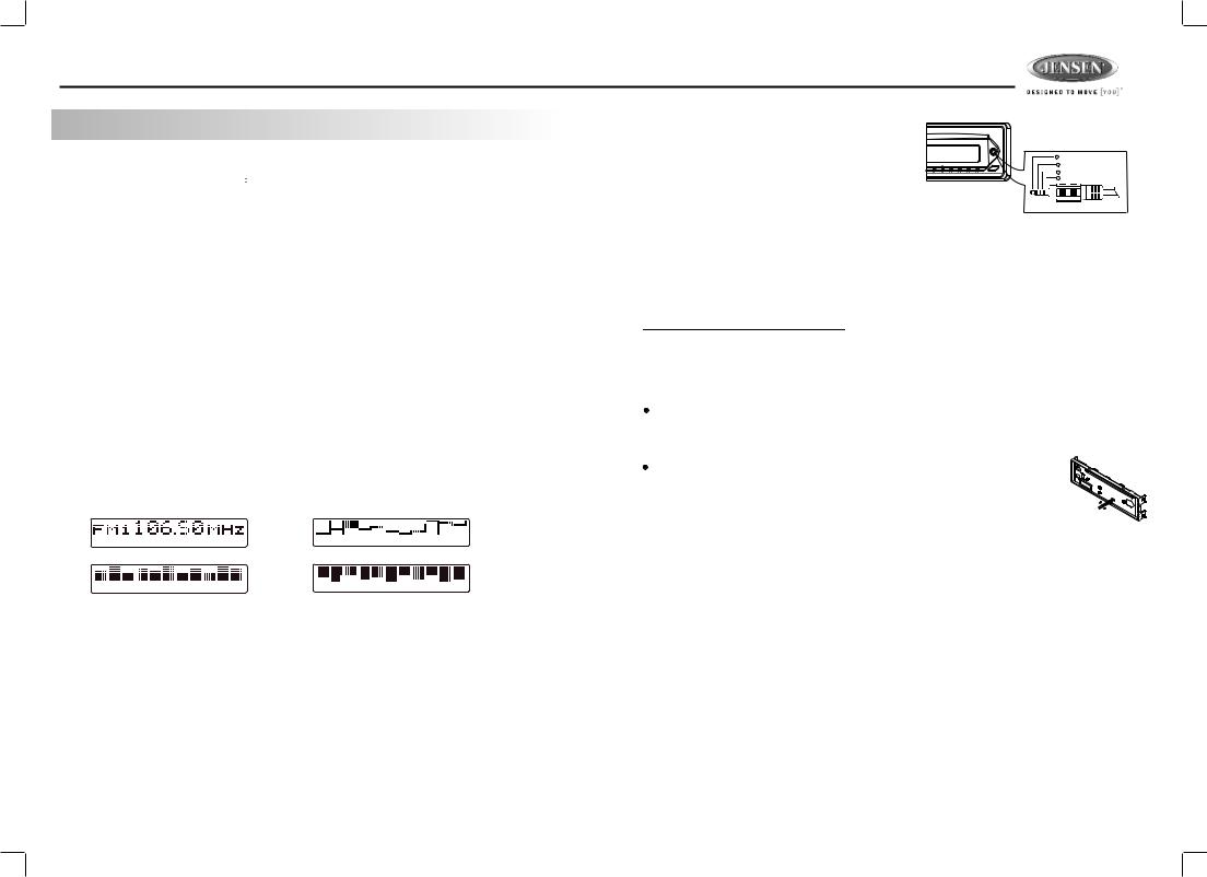
18) DISPLAY (D)
Short Press the DISPLAY button repeatedly to select the following different Display options: Spectrum mode 1 > Spectrum mode 2 > Spectrum mode 3 > Default Display.
The selected DISPLAY will appear in the display when the unit is turned on.
Default Display |
True Spectrum Analyzer mode 2 |
True Spectrum Analyzer mode1 |
True Spectrum Analyzer mode 3 |
22) FRONT PANEL A/V IN JACK
The unit is allowed to connect with external Audio / 
Video system such like Digital Camera or DVD
Console. You can connect the external A/V system |
1 |
Left Audio |
|
2 Right Audio |
|||
thru the A/V in jack on front panel. After connect with |
|||
3 |
Ground |
||
4 Video
external A/V system, pressing mode to “A/V In 2” to
enjoy this external A/V system on this unit.
3.5mm A/V Cable ( not included )
 The unit is only support the 3.5mm A/V Jack Pin Assignment shown as diagram.
9) LO / DX BUTTON
This feature is used to designate the strength of the signals at which the radio will stop during automatic tuning. "Distance" is the default, allowing the radio to stop at a broader range of signals. To set the unit to select only strong local stations during automatic tuning,press this button until "Local" appears in the display.
6) ENCODER VOLUME BUTTON
To increase the volume, rotate the volume control knob clockwise.
To decrease the volume, rotate the volume control knob counter clockwise.
When the volume is adjusted, the volume level is shown on the display panel as a number ranging from 00 (lowest) to 46 (highest).
RESET
To Reset the Main Unit System
After releasing the front panel, use a pencil or any non-metalic object to press & hold the reset button for five seconds to reset the main unit and the unit will return to the factory default settings. 
To Reset the DVD Setting
Press SET UP button on remote control or long press AS/PS button to bring up the SET UP Menu, select MISC then select use Default settings, the DVD Setting will resume to factory default value .
7
 Loading...