


JDVD1500
DVD / CD / AM-FM RECEIVER
Installation and Operation Manual

JDVD1500
CONTENTS |
|
Introduction............................................................................................................................... |
1 |
Safety Information .................................................................................................................... |
2 |
Disc Notes ................................................................................................................................ |
3 |
Installation ................................................................................................................................ |
4 |
Wiring ....................................................................................................................................... |
6 |
Basic Operation ........................................................................................................................ |
8 |
Tuner Operation...................................................................................................................... |
10 |
MP3/WMA Operation ............................................................................................................... |
11 |
DISC Operation ...................................................................................................................... |
13 |
Bluetooth Operation................................................................................................................ |
16 |
Remote Control Operation ...................................................................................................... |
17 |
Setup Menu ............................................................................................................................ |
18 |
Care and Maintenance ........................................................................................................... |
20 |
Troubleshooting ...................................................................................................................... |
20 |
Specifications ......................................................................................................................... |
21 |
ii
JDVD1500
INTRODUCTION
System Features
Features of Jensen JDVD1500 mobile audio system include:
3-Wire power (ACC, Batt, Gnd)
1-DIN (sleeve-mount) chassis design
Segmented LCD Display
White LED panel illumination
Electronic AM/FM tuner (US / Euro)
Station presets (18FM, 12AM)
Auto-Store (AS)/ Preset Scan (PS)
Single DVD / CD player (Plays DVD, CD-A, CD-R/RW Media)
Plays MP3 and WMA Encoded Discs
Electronic Skip Protection (ESP) CD (8 Sec) DVD (3 Sec)
Front panel Aux Video / Stereo Audio input (3.5mm)
Encoded rotary volume control
Audio Mute / Loudness
Preset EQ (Pop, Rock, Classic)
2 Stereo Pre-amp Audio Outputs (RCA)
2 Composite Video Output (RCA)
4x40W Maximum Audio Power Output
Wireless (Jensen IR Codes) Credit Card size remote control (included)
Content List
Jensen Radio
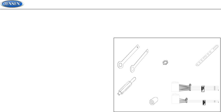
Hardware Kit
Installation Manual
Quick Reference Guide
HARDWARE KIT CONTENTS
KEY |
MOUNTING STRAP |
|
SPRING WASHER
BLUNT CUT HARNESS
MOUNTING SCREW
MOUNTING BUSHING
1

JDVD1500
SAFETY INFORMATION
When Driving
Keep the volume level low enough to be aware of the road and traffic conditions.
When Washing Your Vehicle
Do not expose the product to water or excessive moisture. Moisture can cause electrical shorts, fire or other damage.
When Parked
Parking in direct sunlight can produce very high temperatures inside your vehicle. Give the interior a chance to cool down before starting playback.
Use the Proper Power Supply
This product is designed to operate with a 12 volt DC negative ground battery system.
Protect the Disc Mechanism
Avoid inserting any foreign objects into the disc slot. Misuse may cause malfunction or permanent damage due to the precise mechanism of this unit.
CAUTION:
THIS MOBILE CD PLAYER IS A CLASS I LASER PRODUCT THAT USES A VISIBLE/ INVISIBLE LASER BEAM WHICH COULD CAUSE HAZARDOUS RADIATION EXPOSURE IF IMPROPERLY DIRECTED. BE SURE TO OPERATE THE MOBILE CD PLAYER AS INSTRUCTED.
USE OF CONTROLS OR ADJUSTMENTS OR PERFORMANCE OF PROCEDURES OTHER THAN THOSE SPECIFIED HEREIN MAY RESULT IN HAZARDOUS RADIATION EXPOSURE. DO NOT OPEN COVERS AND DO NOT ATTEMPT TO REPAIR THE UNIT YOURSELF. REFER SERVICING TO QUALIFIED PERSONNEL.
WARNING:
TO REDUCE THE RISK OF FIRE OR ELECTRIC SHOCK, DO NOT EXPOSE THIS EQUIPMENT TO RAIN OR MOISTURE.
TO REDUCE THE RISK OF FIRE OR ELECTRIC SHOCK AND ANNOYING INTERFERENCE, USE ONLY THE RECOMMENDED ACCESSORIES.
This product incorporates copyright protection technology that is protected by method claims of certain U.S. Patents and other intellectual property rights owned by Macrovision Corporation and other rights owners. Use of this copyright protection technology must be authorized by Macrovision Corporation, and is intended for home and other limited viewing uses only unless otherwise authorized by Macrovision Corporation. Reverse engineering or disassembly is prohibited.
Region Management Information
This Mobile DVD Player is designed and manufactured to respond to the Region Management Information recorded on individual DVD discs. If the Region number described on the DVD disc does not correspond to the Region number(s) supported by this Mobile DVD Player, the disc will not play in this unit.
2

JDVD1500
DISC NOTES
Compatible Disc Types
DVD Video
DVDs contain excellent sound and video quality due to Dolby Digital and MPEG2 encoding. A DVD is 12 cm in diameter and can hold more than seven times the data of a CD-ROM. The maximum playing time can be up to 2 hours (a double-sided DVD is up to 4 hours). There are four types of DVD discs: single-layer single-sided (1), two-layer single-sided (2), single-layer double-sided (3), and two-layer double-sided (4).
CD-DA
CD-DA discs can play voice data. The playing time of the standard 12 cm CD-DA disc is 74 minutes.
DTS-CD
DTS digital surround sound uses 6 digital audio tracks to replace the analog voice tracks in movies.
HDCD
HDCD, or “High Definition Compatible Digital,” is a recording/playing technology that improves CD audio quality. Based on full compliance with CD specifications, it can enhance the quality and quantity of digital sounds in the highest scale. It encodes the required messages that were deserted by the CD format, and stores the related commands into the LSB. Without changing the CD format, it is output through the 24-bit D/A converter, which will ultimately enhance the quality of playback.
MP3/WMA/JPEG
This unit is compatible with CD-R, CD-RW, and CD-ROM discs containing MP3, WMA, and JPEG tracks.
CD-R/CD-RW
This unit is compatible with CD-R and CR-RW discs that support ISO9660 specifications. “.MP3”, “.JPG”, “.JPEG”, “.AC3”, “.PCM”, “.MPG”, “.MPE”, and “.WAV” formats can be included on
ISO9660-compatible discs.
DVD-R / DVD-RW
This unit is compatible with DVD-R and DVD-RW discs that support UDF specifications. “.MP3”, “.JPG”, “.JPEG”, “.AC3”, ”.PCM”, “.MPG”, “.MPE”, and “.WAV” formats can be included on
UDF-compatible discs.
Incompatible Disc Types
8 cm disc
CD ROM
CDV, CDI, CDG
LD
DVD ROM
DVD RAM
NOTE: DVD-R and DVD-RW discs will not play unless the recording session is closed and the CD is finalized.
Table 1: General Disc Information
Disc Type |
Logo |
Diameter/ |
Playback Time |
|
Playable Sides |
||||
|
|
|
||
|
|
|
|
|
DVD Video |
|
12cm single/double |
133 minutes (4.7 GB) |
|
|
|
side |
242 minutes (8.5 GB) |
|
|
|
(1 layer or 2 layers) |
266 minutes (9.4 GB) |
|
|
|
|
484 minutes (17 GB) |
|
Audio CD |
|
12cm single side |
74 minutes |
|
|
|
|
|
|
MP3/MWA |
CD-Rs or CD-RWs recorded in MP3, MPEG1 or 2, 2.5 Audio Layer 3 and |
|||
Disc |
WMA Version 7 and 8. The recorded format must be compliant with ISO |
|||
|
9660 Level 1, ISO 9660 Level 2, Romeo, or Joliet. |
|
||
Disc Maintenance
A dirty or defective disc may cause sound dropouts while playing. Before playing, wipe the disc using a clean cloth, working from the center hole towards the outside edge. Never use benzene, thinners, cleaning fluids, anti-static liquids or any other solvent.
Insert label side up. |
Do not bend. |
Never touch the |
Wipe clean from this |
|
|
underside of the disc. |
center to the edge. |
NOTE: A disc may become scratched (although not enough to make it unusable) depending on how you handle it and other conditions in the usage environment. These scratches are not an indication of a problem with the player.
3
JDVD1500
INSTALLATION
This unit is designed for installation in vehicle cabs with an existing 1-DIN radio opening. In many cases, a special installation kit will be required to mount the radio to the dashboard. See the dealer where the radio was purchased for kit availability. Always check the kit application before purchasing to make sure the kit works with your vehicle.
Before you Begin
1.Disconnect Battery
Before you begin, always disconnect the battery negative terminal.
2.Remove Transport Screws
Important Notes
Before final installation, test the wiring connections to make sure the unit is connected properly and the system works.
Use only the parts included with the unit to ensure proper installation. The use of unauthorized parts can cause malfunctions.
Consult with your nearest dealer if installation requires the drilling of holes or other modifications to your vehicle.
Install the unit where it does not interfere with driving and cannot injure passengers during a sudden or emergency stop.
If the installation angle exceeds 30° from horizontal, the unit might not give optimum performance.
Avoid installing the unit where it will be subjected to high temperatures from direct sunlight, hot air, or from a heater, or subject to excessive dust, dirt or vibration.
DIN Front Mount
1.Slide the mounting sleeve off of the chassis if it has not already been removed. If it is locked into position, use the removal
keys (supplied) to disengage it. The removal keys are depicted in “DIN Rear Mount” on page 4.
2.Check the dashboard opening size by sliding the mounting sleeve into it. If the opening is not large enough, carefully cut or file as necessary until the sleeve easily slides into the opening. Do not force the sleeve into the opening or cause it to bend or bow. Check that there will be sufficient space behind the dashboard for the radio chassis.
4
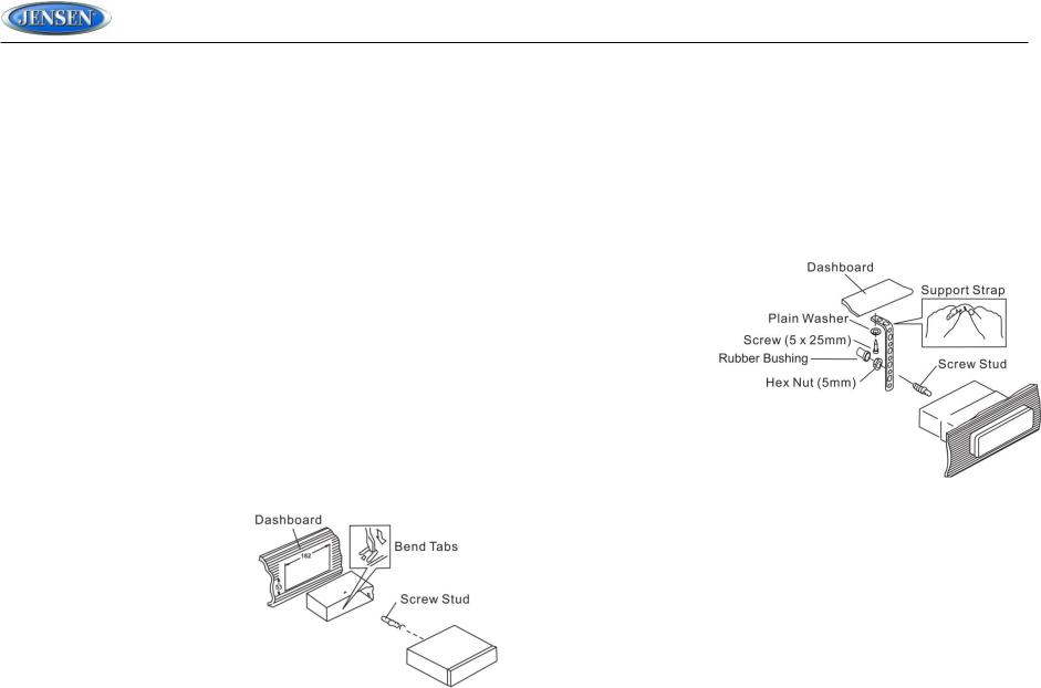
3.Locate the series of bend tabs along the top, bottom and sides of the mounting sleeve. With the sleeve fully inserted into the dashboard opening, bend as many of the tabs outward as necessary to firmly secure the sleeve to the dashboard.
4.Place the radio in front of the dashboard opening so the wiring can be brought through the mounting sleeve.
5.Follow the wiring diagram carefully and make certain all connections are secure and insulated with crimp connectors or electrical tape to ensure proper operation.
6.After completing the wiring connections, turn the unit on to confirm operation (vehicle accessory switch must be on). If the unit does not operate, recheck all wiring until the problem is corrected. Once proper operation is achieved, turn the accessory switch off and proceed with final mounting of the chassis.
7.Carefully slide the radio into the mounting sleeve making sure it is right-side-up until it is fully seated and the spring
clips lock it into place.
8.Attach one end of the perforated support strap (supplied) to the screw stud on the rear of the chassis using the hex nut provided. Fasten the other end of the perforated strap to a secure part of the dashboard either above or below the radio using the screw and plain washer provided. Bend the strap, as necessary, to
position it. Some vehicle installations provide cavity for rear support. In these applications, place the rubber bushing over the screw stud and insert the radio.
CAUTION: The perforated rear support strap or rear rubber mounting bushing must be used in the installation of the radio. Installation without either may result in damage to the radio or the mounting surface and void the manufacturer’s warranty.
9.Test radio operation by referring to the operating instructions for the unit.
10.When wiring is complete, reconnect the battery negative terminal.
11.Push the trim plate against the chassis until it is fitted.
DIN Rear Mount
This unit has threaded holes in the chassis side panels which may be used with the original factory mounting brackets of some vehicles to mount the radio to the dashboard. Please consult with your local mobile stereo shop for assistance on this type of installation.
1.Remove the existing factory radio from the dashboard or center console mounting. Save all hardware and brackets as they will be used to mount the new radio.

JDVD1500
2.Carefully unsnap the plastic trim ring from the front of the new radio chassis. Remove and discard the trim ring.
3.Remove the factory mounting brackets and hardware from the existing radio and attach them to the new radio. Select a position where the screw holes of the bracket and the screw holes of the main unit are aligned (are fitted). Tighten the
screws at 2 places on each side. Do not exceed M5 x 9 MM maximum screw size. Longer screws may damage components inside the chassis.
4.Wire the new radio to the vehicle as outlined in the Universal Installation instructions.
5.When wiring is complete, reconnect the battery negative terminal.
6.Mount the new radio assembly to the dashboard or center console using the reverse procedure of step 1.
NOTE: The mounting box, outer trim ring, and half-sleeve are not used for DIN rear mount.
Removing the Unit (DIN Front Mount)
To remove the radio after installation:
1.Insert fingers into the groove in the front of frame and pull out to remove the frame.
(When re-attaching the frame, point the side with a groove downwards and re-attach.)
2.Insert the removal keys straight back until they click, and then pull the radio out. If removal keys are inserted at an angle, they will not lock properly to release the unit.
5

JDVD1500
WIRING
|
DETAIL A |
|
SHOWN FROM PIN VIEW |
PIN NO. |
DESCRIPTION |
|
|
A1 |
GROUND |
A2 |
NO CONNECTION |
A3 |
+12VDC BATTERY CONSTANT |
A4 |
NO CONNECTION |
A5 |
NO CONNECTION |
A6 |
NO CONNECTION |
A7 |
AMP REMOTE |
A8 |
+12VDC SWITCHED |
B1 |
LEFT REAR SPEAKER (-) |
B2 |
LEFT FRONT SPEAKER (-) |
|
|
B3 |
RIGHT FRONT SPEAKER (-) |
B4 |
RIGHT REAR SPEAKER (-) |
|
|
B5 |
RIGHT REAR SPEAKER (+) |
B6 |
RIGHT FRONT SPEAKER (+) |
B7 |
LEFT FRONT SPEAKER (+) |
|
|
B8 |
LEFT REAR SPEAKER (+) |
6
 Loading...