


HP EliteBook 2730p Notebook PC
Maintenance and Service Guide
Document Part Number: 483222-002
March 2012
This guide is a troubleshooting reference used for maintaining and servicing the computer. It provides comprehensive information on identifying computer features, components, and spare parts; troubleshooting computer problems; and performing computer disassembly procedures.
© Copyright 2008, 2012 Hewlett-Packard Development Company, L.P.
Microsoft, Windows, and Windows Vista are U.S. registered trademarks of Microsoft Corporation. SD Logo is a trademark of its proprietor. Bluetooth is a trademark owned by its proprietor and used by Hewlett-Packard Company under license. Intel and Core are trademarks or registered trademarks of Intel Corporation or its subsidiaries in the United States and other countries. Java is a U.S. trademark of Sun Microsystems, Inc.
The information contained herein is subject to change without notice. The only warranties for HP products and services are set forth in the express warranty statements accompanying such products and services. Nothing herein should be construed as constituting an additional warranty. HP shall not be liable for technical or editorial errors or omissions contained herein.
Second Edition: March 2012
First Edition: October 2008
Document Part Number: 483222-002

Safety warning notice
ÅWARNING: To reduce the possibility of heat-related injuries or of overheating the computer, do not place the computer directly on your lap or obstruct the computer air vents. Use the computer only on a hard, flat surface. Do not allow another hard surface, such as an adjoining optional printer, or a soft surface, such as pillows or rugs or clothing, to block airflow. Also, do not allow the AC adapter to contact the skin or a soft surface, such as pillows or rugs or clothing, during operation. The computer and the AC adapter comply with the user-accessible surface temperature limits defined by the International Standard for Safety of Information Technology Equipment (IEC 60950).

Contents
1Product description
2External component identification
Top components. . . . . . . . . . . . . . . . . . . . . . . . . . . . . . . . . . . . . . . . . . . . . . . . . . . . . . . . . . . . . . . . . . . . . . 2–1 Wireless antenna locations . . . . . . . . . . . . . . . . . . . . . . . . . . . . . . . . . . . . . . . . . . . . . . . . . . . . . . . . . . 2–1 Display components . . . . . . . . . . . . . . . . . . . . . . . . . . . . . . . . . . . . . . . . . . . . . . . . . . . . . . . . . . . . . . . 2–2 Buttons and switches. . . . . . . . . . . . . . . . . . . . . . . . . . . . . . . . . . . . . . . . . . . . . . . . . . . . . . . . . . . . . . . 2–3 Keys . . . . . . . . . . . . . . . . . . . . . . . . . . . . . . . . . . . . . . . . . . . . . . . . . . . . . . . . . . . . . . . . . . . . . . . . . . . 2–4 Lights . . . . . . . . . . . . . . . . . . . . . . . . . . . . . . . . . . . . . . . . . . . . . . . . . . . . . . . . . . . . . . . . . . . . . . . . . . 2–5 Pointing devices . . . . . . . . . . . . . . . . . . . . . . . . . . . . . . . . . . . . . . . . . . . . . . . . . . . . . . . . . . . . . . . . . . 2–6
Front components. . . . . . . . . . . . . . . . . . . . . . . . . . . . . . . . . . . . . . . . . . . . . . . . . . . . . . . . . . . . . . . . . . . . . 2–7 Right-side components. . . . . . . . . . . . . . . . . . . . . . . . . . . . . . . . . . . . . . . . . . . . . . . . . . . . . . . . . . . . . . . . . 2–8 Left-side components . . . . . . . . . . . . . . . . . . . . . . . . . . . . . . . . . . . . . . . . . . . . . . . . . . . . . . . . . . . . . . . . . . 2–9 Rear components . . . . . . . . . . . . . . . . . . . . . . . . . . . . . . . . . . . . . . . . . . . . . . . . . . . . . . . . . . . . . . . . . . . . 2–11 Bottom components . . . . . . . . . . . . . . . . . . . . . . . . . . . . . . . . . . . . . . . . . . . . . . . . . . . . . . . . . . . . . . . . . . 2–12
3 Illustrated parts catalog
Serial number location . . . . . . . . . . . . . . . . . . . . . . . . . . . . . . . . . . . . . . . . . . . . . . . . . . . . . . . . . . . . . . . . . 3–1 Computer major components . . . . . . . . . . . . . . . . . . . . . . . . . . . . . . . . . . . . . . . . . . . . . . . . . . . . . . . . . . . . 3–2 Cable Kit . . . . . . . . . . . . . . . . . . . . . . . . . . . . . . . . . . . . . . . . . . . . . . . . . . . . . . . . . . . . . . . . . . . . . . . . . . . 3–7 Mass storage devices . . . . . . . . . . . . . . . . . . . . . . . . . . . . . . . . . . . . . . . . . . . . . . . . . . . . . . . . . . . . . . . . . . 3–8 Plastics Kit . . . . . . . . . . . . . . . . . . . . . . . . . . . . . . . . . . . . . . . . . . . . . . . . . . . . . . . . . . . . . . . . . . . . . . . . . . 3–9 Miscellaneous parts . . . . . . . . . . . . . . . . . . . . . . . . . . . . . . . . . . . . . . . . . . . . . . . . . . . . . . . . . . . . . . . . . . 3–10 Sequential part number listing . . . . . . . . . . . . . . . . . . . . . . . . . . . . . . . . . . . . . . . . . . . . . . . . . . . . . . . . . . 3–11
4 Removal and replacement procedures
Preliminary replacement requirements . . . . . . . . . . . . . . . . . . . . . . . . . . . . . . . . . . . . . . . . . . . . . . . . . . . . 4–1 Tools required . . . . . . . . . . . . . . . . . . . . . . . . . . . . . . . . . . . . . . . . . . . . . . . . . . . . . . . . . . . . . . . . . . . . 4–1 Service considerations. . . . . . . . . . . . . . . . . . . . . . . . . . . . . . . . . . . . . . . . . . . . . . . . . . . . . . . . . . . . . . 4–1 Grounding guidelines . . . . . . . . . . . . . . . . . . . . . . . . . . . . . . . . . . . . . . . . . . . . . . . . . . . . . . . . . . . . . . 4–2 Unknown user password . . . . . . . . . . . . . . . . . . . . . . . . . . . . . . . . . . . . . . . . . . . . . . . . . . . . . . . . . . . . 4–5
Component replacement procedures . . . . . . . . . . . . . . . . . . . . . . . . . . . . . . . . . . . . . . . . . . . . . . . . . . . . . . 4–6 Serial number location . . . . . . . . . . . . . . . . . . . . . . . . . . . . . . . . . . . . . . . . . . . . . . . . . . . . . . . . . . . . . 4–6 Computer feet . . . . . . . . . . . . . . . . . . . . . . . . . . . . . . . . . . . . . . . . . . . . . . . . . . . . . . . . . . . . . . . . . . . . 4–7 Battery. . . . . . . . . . . . . . . . . . . . . . . . . . . . . . . . . . . . . . . . . . . . . . . . . . . . . . . . . . . . . . . . . . . . . . . . . . 4–8 SIM . . . . . . . . . . . . . . . . . . . . . . . . . . . . . . . . . . . . . . . . . . . . . . . . . . . . . . . . . . . . . . . . . . . . . . . . . . . . 4–9 Hard drive . . . . . . . . . . . . . . . . . . . . . . . . . . . . . . . . . . . . . . . . . . . . . . . . . . . . . . . . . . . . . . . . . . . . . . 4–10 WLAN module . . . . . . . . . . . . . . . . . . . . . . . . . . . . . . . . . . . . . . . . . . . . . . . . . . . . . . . . . . . . . . . . . . 4–12 WWAN module . . . . . . . . . . . . . . . . . . . . . . . . . . . . . . . . . . . . . . . . . . . . . . . . . . . . . . . . . . . . . . . . . 4–15 Memory module . . . . . . . . . . . . . . . . . . . . . . . . . . . . . . . . . . . . . . . . . . . . . . . . . . . . . . . . . . . . . . . . . 4–16 Keyboard. . . . . . . . . . . . . . . . . . . . . . . . . . . . . . . . . . . . . . . . . . . . . . . . . . . . . . . . . . . . . . . . . . . . . . . 4–17 Hinge cover . . . . . . . . . . . . . . . . . . . . . . . . . . . . . . . . . . . . . . . . . . . . . . . . . . . . . . . . . . . . . . . . . . . . . 4–20
Maintenance and Service Guide |
v |

Contents
Top cover . . . . . . . . . . . . . . . . . . . . . . . . . . . . . . . . . . . . . . . . . . . . . . . . . . . . . . . . . . . . . . . . . . . . . . 4–21 RTC battery. . . . . . . . . . . . . . . . . . . . . . . . . . . . . . . . . . . . . . . . . . . . . . . . . . . . . . . . . . . . . . . . . . . . . 4–23 Audio connector board . . . . . . . . . . . . . . . . . . . . . . . . . . . . . . . . . . . . . . . . . . . . . . . . . . . . . . . . . . . . 4–24 Bluetooth module . . . . . . . . . . . . . . . . . . . . . . . . . . . . . . . . . . . . . . . . . . . . . . . . . . . . . . . . . . . . . . . . 4–25 Speaker . . . . . . . . . . . . . . . . . . . . . . . . . . . . . . . . . . . . . . . . . . . . . . . . . . . . . . . . . . . . . . . . . . . . . . . . 4–26 Display assembly . . . . . . . . . . . . . . . . . . . . . . . . . . . . . . . . . . . . . . . . . . . . . . . . . . . . . . . . . . . . . . . . 4–27 System board. . . . . . . . . . . . . . . . . . . . . . . . . . . . . . . . . . . . . . . . . . . . . . . . . . . . . . . . . . . . . . . . . . . . 4–30 Fan/heat sink assembly . . . . . . . . . . . . . . . . . . . . . . . . . . . . . . . . . . . . . . . . . . . . . . . . . . . . . . . . . . . . 4–34 Modem module . . . . . . . . . . . . . . . . . . . . . . . . . . . . . . . . . . . . . . . . . . . . . . . . . . . . . . . . . . . . . . . . . . 4–36
5 Computer Setup
Starting Computer Setup . . . . . . . . . . . . . . . . . . . . . . . . . . . . . . . . . . . . . . . . . . . . . . . . . . . . . . . . . . . . . . . 5–1 Using Computer Setup . . . . . . . . . . . . . . . . . . . . . . . . . . . . . . . . . . . . . . . . . . . . . . . . . . . . . . . . . . . . . . . . . 5–2 Navigating and selecting in Computer Setup . . . . . . . . . . . . . . . . . . . . . . . . . . . . . . . . . . . . . . . . . . . . 5–2 Restoring factory settings in Computer Setup . . . . . . . . . . . . . . . . . . . . . . . . . . . . . . . . . . . . . . . . . . . 5–3 Computer Setup menus . . . . . . . . . . . . . . . . . . . . . . . . . . . . . . . . . . . . . . . . . . . . . . . . . . . . . . . . . . . . . . . . 5–3 File menu. . . . . . . . . . . . . . . . . . . . . . . . . . . . . . . . . . . . . . . . . . . . . . . . . . . . . . . . . . . . . . . . . . . . . . . . 5–3 Security menu . . . . . . . . . . . . . . . . . . . . . . . . . . . . . . . . . . . . . . . . . . . . . . . . . . . . . . . . . . . . . . . . . . . . 5–4 Diagnostics menu . . . . . . . . . . . . . . . . . . . . . . . . . . . . . . . . . . . . . . . . . . . . . . . . . . . . . . . . . . . . . . . . . 5–5 System Configuration menu . . . . . . . . . . . . . . . . . . . . . . . . . . . . . . . . . . . . . . . . . . . . . . . . . . . . . . . . . 5–5
6 Specifications
Computer specifications. . . . . . . . . . . . . . . . . . . . . . . . . . . . . . . . . . . . . . . . . . . . . . . . . . . . . . . . . . . . . . . . 6–1 12.1-inch, WXGA display specifications. . . . . . . . . . . . . . . . . . . . . . . . . . . . . . . . . . . . . . . . . . . . . . . . . . . 6–2 Hard drive specifications . . . . . . . . . . . . . . . . . . . . . . . . . . . . . . . . . . . . . . . . . . . . . . . . . . . . . . . . . . . . . . . 6–2 System DMA specifications. . . . . . . . . . . . . . . . . . . . . . . . . . . . . . . . . . . . . . . . . . . . . . . . . . . . . . . . . . . . . 6–3 System interrupt specifications . . . . . . . . . . . . . . . . . . . . . . . . . . . . . . . . . . . . . . . . . . . . . . . . . . . . . . . . . . 6–3 System I/O address specifications . . . . . . . . . . . . . . . . . . . . . . . . . . . . . . . . . . . . . . . . . . . . . . . . . . . . . . . . 6–4 System memory map specifications. . . . . . . . . . . . . . . . . . . . . . . . . . . . . . . . . . . . . . . . . . . . . . . . . . . . . . . 6–6
7 Screw listing
Phillips PM2.0×5.0 captive screw . . . . . . . . . . . . . . . . . . . . . . . . . . . . . . . . . . . . . . . . . . . . . . . . . . . . . . . . 7–1 Phillips PM2.0×3.0 screw . . . . . . . . . . . . . . . . . . . . . . . . . . . . . . . . . . . . . . . . . . . . . . . . . . . . . . . . . . . . . . 7–2 Phillips PM2.0×4.0 screw . . . . . . . . . . . . . . . . . . . . . . . . . . . . . . . . . . . . . . . . . . . . . . . . . . . . . . . . . . . . . . 7–3 Torx T8M2.0×8.0 screw . . . . . . . . . . . . . . . . . . . . . . . . . . . . . . . . . . . . . . . . . . . . . . . . . . . . . . . . . . . . . . . 7–4 Torx T8M2.0×5.0 screw . . . . . . . . . . . . . . . . . . . . . . . . . . . . . . . . . . . . . . . . . . . . . . . . . . . . . . . . . . . . . . . 7–5 Phillips PM2.0×5.0 screw . . . . . . . . . . . . . . . . . . . . . . . . . . . . . . . . . . . . . . . . . . . . . . . . . . . . . . . . . . . . . . 7–6 Phillips PM2.0×4.0 screw . . . . . . . . . . . . . . . . . . . . . . . . . . . . . . . . . . . . . . . . . . . . . . . . . . . . . . . . . . . . . . 7–8 Torx T8M2.5×6.0 screw . . . . . . . . . . . . . . . . . . . . . . . . . . . . . . . . . . . . . . . . . . . . . . . . . . . . . . . . . . . . . . . 7–9 Phillips PM2.5×7.0 captive screw . . . . . . . . . . . . . . . . . . . . . . . . . . . . . . . . . . . . . . . . . . . . . . . . . . . . . . . 7–10
8 Backup and recovery
Backup and recovery in Windows Vista . . . . . . . . . . . . . . . . . . . . . . . . . . . . . . . . . . . . . . . . . . . . . . . . . . . 8–1 Overview. . . . . . . . . . . . . . . . . . . . . . . . . . . . . . . . . . . . . . . . . . . . . . . . . . . . . . . . . . . . . . . . . . . . . . . . 8–1 Backing up your information . . . . . . . . . . . . . . . . . . . . . . . . . . . . . . . . . . . . . . . . . . . . . . . . . . . . . . . . 8–1 Performing a recovery. . . . . . . . . . . . . . . . . . . . . . . . . . . . . . . . . . . . . . . . . . . . . . . . . . . . . . . . . . . . . . 8–2 Backup and recovery in Windows XP . . . . . . . . . . . . . . . . . . . . . . . . . . . . . . . . . . . . . . . . . . . . . . . . . . . . . 8–5 Overview. . . . . . . . . . . . . . . . . . . . . . . . . . . . . . . . . . . . . . . . . . . . . . . . . . . . . . . . . . . . . . . . . . . . . . . . 8–5 Backing up your information . . . . . . . . . . . . . . . . . . . . . . . . . . . . . . . . . . . . . . . . . . . . . . . . . . . . . . . . 8–5 Performing a recovery. . . . . . . . . . . . . . . . . . . . . . . . . . . . . . . . . . . . . . . . . . . . . . . . . . . . . . . . . . . . . . 8–6
vi |
Maintenance and Service Guide |

Contents
9 Connector pin assignments
1394 . . . . . . . . . . . . . . . . . . . . . . . . . . . . . . . . . . . . . . . . . . . . . . . . . . . . . . . . . . . . . . . . . . . . . . . . . . . . . . . 9–1 Audio-in (microphone). . . . . . . . . . . . . . . . . . . . . . . . . . . . . . . . . . . . . . . . . . . . . . . . . . . . . . . . . . . . . . . . . 9–2 Audio-out (headphone) . . . . . . . . . . . . . . . . . . . . . . . . . . . . . . . . . . . . . . . . . . . . . . . . . . . . . . . . . . . . . . . . 9–2 External monitor. . . . . . . . . . . . . . . . . . . . . . . . . . . . . . . . . . . . . . . . . . . . . . . . . . . . . . . . . . . . . . . . . . . . . . 9–3 RJ-11 (modem). . . . . . . . . . . . . . . . . . . . . . . . . . . . . . . . . . . . . . . . . . . . . . . . . . . . . . . . . . . . . . . . . . . . . . . 9–4 RJ-45 (network) . . . . . . . . . . . . . . . . . . . . . . . . . . . . . . . . . . . . . . . . . . . . . . . . . . . . . . . . . . . . . . . . . . . . . . 9–5 Universal Serial Bus. . . . . . . . . . . . . . . . . . . . . . . . . . . . . . . . . . . . . . . . . . . . . . . . . . . . . . . . . . . . . . . . . . . 9–6
10Power cord set requirements
Requirements for all countries and regions . . . . . . . . . . . . . . . . . . . . . . . . . . . . . . . . . . . . . . . . . . . . . . . . 10–1 Requirements for specific countries and regions . . . . . . . . . . . . . . . . . . . . . . . . . . . . . . . . . . . . . . . . . . . . 10–2
11Recycling
Battery . . . . . . . . . . . . . . . . . . . . . . . . . . . . . . . . . . . . . . . . . . . . . . . . . . . . . . . . . . . . . . . . . . . . . . . . . . . . 11–1
Display . . . . . . . . . . . . . . . . . . . . . . . . . . . . . . . . . . . . . . . . . . . . . . . . . . . . . . . . . . . . . . . . . . . . . . . . . . . . 11–1
Index
Maintenance and Service Guide |
vii |

Contents
viii |
Maintenance and Service Guide |

1
Product description
Category |
Description |
|
|
Product Name |
HP EliteBook 2730p Notebook PC |
|
|
Processors |
Intel® Core™2 Duo ultra low-voltage, non-socketed processors: |
|
|
|
■ SL9600 2.13-GHz processor, 6-MB L2 cache, 1066-MHz front side bus (FSB) |
|
■ SL9400 1.86-GHz processor, 6-MB L2 cache, 1066-MHz FSB |
|
■ SL9300 1.60-GHz processor, 6-MB L2 cache, 1066-MHz FSB |
|
■ SU9400 1.40-GHz processor, 3-MB L2 cache, 800-MHz FSB |
|
■ SU9300 1.20-GHz processor, 3-MB L2 cache, 800-MHz FSB |
|
|
Chipset |
Northbridge: Cantiga GS |
|
Southbridge: Intel ICH9M SFF enhanced |
|
|
Graphics |
Intel Graphics Media Accelerator X4500 HD Unified Memory Architecture (UMA) graphics |
|
subsystem integrated with shared system memory (dynamically allocated) with up to 384 MB |
|
shared system memory |
|
|
Panel |
Digitizer with pen support |
|
Sparkle-free glass |
|
Integrated keyboard light |
|
2 wireless local area network (WLAN) antennae |
|
|
|
Supports the following display assemblies: |
|
■ 12.1-inch WXGA LED AntiGlare (1280 × 800) with webcam and outdoor light |
|
■ 12.1-inch WXGA LED AntiGlare (1280 × 800) with webcam |
|
■ 12.1-inch WXGA LED AntiGlare (1280 × 800) with outdoor light |
|
■ 12.1-inch WXGA LED AntiGlare (1280 × 800) |
|
|
Memory |
2 customer-accessible/upgradable memory module slots |
|
Supports dual-channel memory |
|
Supports PC2-6400, 800-MHz, DDR2 memory modules |
|
Up to 8192-GB maximum memory supported |
Supports the following configurations:
■8192-MB total system memory (4096 × 2, dual-channel)
■6144-MB total system memory (4096 + 2048)
■5120-MB total system memory (4096 + 1024)
■4096-MB total system memory (2048 × 2, dual-channel)
■3072-MB total system memory (2048 + 1024)
■2048-MB total system memory (1024 × 2, dual-channel)
■2048-MB total system memory (2048 × 1)
■1024-MB total system memory (1024 × 1)
(Continued)
Maintenance and Service Guide |
1–1 |

Product description
Category |
Description |
|
|
Mass storage drives |
Supports 45.72-mm (1.80-inch) hard drives and 45.72-mm (1.80-inch) solid-state drives |
|
Customer-accessible |
|
Serial ATA |
|
HP 3D DriveGuard |
|
|
|
Supports the following drives: |
|
■ 250-GB, 5400-rpm hard drive |
|
■ 160-GB, 5400-rpm hard drive |
|
■ 120-GB, 5400-rpm hard drive |
|
■ 80-GB, 5400-rpm hard drive |
|
■ 128-GB solid-state drive |
|
■ 80-GB solid-state drive |
|
|
Optical drives |
Supports external optical drive only through docking station |
|
|
Diskette drive |
Supports external USB diskette drive only |
|
Supports boot from USB device |
|
|
Microphone |
Integrated dual array microphone |
|
|
Audio |
Analog Devices AD1984A high-definition audio |
|
Single speaker |
|
|
Webcam |
Optional 2.1-megapixel webcam with business card reader support |
|
Business card slot |
|
|
Modem |
56K V.92 1.5-inch data/fax modem with digital line guard |
|
Modem cable is included |
|
Supports no-modem option |
|
|
Ethernet |
Intel 10/100/1000 network interface card (NIC) |
|
NIC power-down technology |
|
Ethernet cable included |
|
S4/S5 wake on LAN |
|
|
Wireless |
Integrated WLAN options by way of wireless module: |
|
2 wireless antennae built into display assembly |
|
Supports no-WLAN option |
|
|
|
Supports the following WLAN formats: |
|
■ Broadcom 802.11a/b/g/n |
|
■ Broadcom 802.11b/g |
|
■ 802.11a/b/g/n Intel with iAMT support |
|
■ 802.11a/b/g Intel with iAMT support |
|
|
|
Integrated wireless wide area network (WWAN) options by way of wireless module: |
|
HSPDA EV-DO WWAN module |
|
2 WWAN antennae built into display assembly (worldwide 5-band) |
|
Supports aftermarket WWAN option |
|
|
|
Subscriber identify module (SIM) user-accessible behind primary battery |
|
|
|
Integrated personal area network (PAN) options by way of Bluetooth® module: |
|
Support for no-WPAN option |
|
Broadcom Bluetooth |
|
|
External media card |
One ExpressCard slot, supporting optional ExpressCard/54 cards |
|
SD Card Reader supporting MultiMediaCard (MMC) and Secure Digital (SD) Memory Cards |
|
|
|
(Continued) |
1–2 |
Maintenance and Service Guide |
Product description
Category |
Description |
|
|
Docking |
HP 2700 Ultra-Slim Expansion Base support |
|
Signals passed through docking connector: |
|
■ External monitor |
|
■ Headphone |
|
■ Microphone |
|
■ Optical drive support |
|
■ Power |
|
■ RJ-45 |
|
■ USB 2.0 |
|
|
Ports |
1394a |
|
Audio-in (mono microphone) |
|
Audio-out (stereo headphone) |
|
Multi-pin AC power |
|
RJ-11 (modem) |
|
RJ-45 (Ethernet, includes link and activity lights) |
|
USB (2, one powered) |
|
VGA (Dsub 15-pin) supporting 1600 × 1200 external resolution at 75 GHz (hot plug/unplug |
|
with auto-detect) |
|
|
Keyboard/pointing device |
Spill-resistant 27.1-mm (10.7-inch) keyboard |
|
Dual-point configuration (TouchPad with 2 TouchPad buttons and pointing stick with 2 |
|
pointing stick buttons) |
|
Durable key caps |
|
Taps enabled as default |
|
|
Power requirements |
65-W HP Smart AC adapter with localized cable plug support (3-wire plug with ground pin, |
|
supports 3-pin DC connector) |
|
6-cell, 2.25-Ah (44-Wh) Li-ion battery |
|
Supports HP2700 Ultra-Slim Battery (travel battery) |
|
|
Security |
Supports security cable slot |
|
Optional integrated Active Smart card reader |
|
Integrated trusted platform module (TPM) 1.2 chip (soldered to system board) |
|
Integrated USB-based fingerprint reader |
|
|
Operating system |
Preinstalled without Microsoft® Office: |
|
Windows Vista® Business 32 |
|
Windows Vista Business 32 with Windows® XPTablet image |
|
FreeDOS |
|
|
|
Preinstalled with Microsoft Office: |
|
Windows Vista Business 32 with Microsoft Office 2007 Ready |
|
Windows Vista Business 32 with Windows XPTablet image and Microsoft Office 2007 Ready |
|
Windows Vista Ultimate 32 with Microsoft Office 2007 Ready |
|
Windows Vista Ultimate 32 with Windows XPTablet image and Microsoft Office 2007 Ready |
|
Windows Vista Business 32 with Microsoft Office 2007 Personal |
|
Windows Vista Business 32 with Windows XPTablet image and Microsoft Office |
|
2007 Personal |
|
Windows Vista Business 32 with Microsoft Office 2007 Personal and PowerPoint |
|
Windows Vista Business 32 with Windows XPTablet image, Microsoft Office 2007 Personal, |
|
and PowerPoint |
|
Windows Vista Business 32 with Microsoft Office 2007 Pro |
|
Windows Vista Business 32 with Windows XPTablet image and Microsoft Office 2007 Pro |
|
|
|
(Continued) |
Maintenance and Service Guide |
1–3 |

Product description
Category |
Description |
|
|
Operating system |
Restore media: |
|
Windows Vista Business 32 |
|
Windows Vista Business 64 |
|
Windows Vista Ultimate 32 |
|
Windows Vista DRDVD |
|
Windows XPTablet |
|
Windows XPTablet DRDVD |
|
Microsoft Office Ready restore DVD |
|
|
|
Certified: Novell SuSE Linux |
|
|
|
Web support: |
|
Windows Vista Enterprise 32 |
|
Windows Vista Enterprise 64 |
|
|
Serviceability |
End-user replaceable parts: |
|
■ AC adapter |
|
■ Battery (system) |
|
■ Hard drive |
|
■ Memory module |
|
■ Optical drive |
|
■ WLAN module |
|
■ WWAN module |
|
|
1–4 |
Maintenance and Service Guide |

2
External component identification
Top components
Wireless antenna locations
Item |
Component |
Description |
|
|
|
1 |
WWAN antenna* |
Sends and receives wireless signals to communicate with wireless wide area |
|
|
networks (WWAN). |
|
|
|
2 |
WLAN antennae (2)* |
Send and receive wireless signals to communicate with wireless local area |
|
|
networks (WLAN). |
|
|
|
3 |
External WWAN antenna |
Sends and receives wireless signals to communicate with wireless wide area |
|
|
networks (WWAN). |
*These antennae are not visible from the outside of the computer. For optimal transmission, keep the areas immediately around the antennae free from obstructions.
To see wireless regulatory notices, refer to the section of the Regulatory, Safety and Environmental Notices that applies to your country or region. These notices are located in Help and Support.
Maintenance and Service Guide |
2–1 |
External component identification
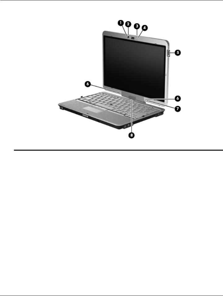
Display components
Item |
Component |
Description |
|
|
|
1 |
Webcam light (select models only) |
On: The webcam is in use. |
|
|
|
2 |
Webcam (select models only) |
Records audio and video and captures still photographs. |
|
|
|
3 |
Keyboard light button |
Opens and turns on the keyboard light. |
|
|
|
4 |
Keyboard light |
Illuminates the keyboard in low-light conditions when the keyboard light button |
|
|
is pressed. |
|
|
|
5 |
HP Fingerprint Sensor |
Allows a fingerprint logon to Windows instead of a password logon. |
|
(fingerprint reader) |
|
|
|
|
6 |
Internal microphones (2) |
Record sound and transmit sound for video conferencing and Voice Over |
|
|
IP (VoIP). |
|
|
|
7 |
Ambient light sensor |
Automatically adjusts the display brightness based on the lighting conditions |
|
|
in your environment. |
|
|
|
8 |
Convertible hinge |
Swivels the display and converts the computer from traditional notebook |
|
|
mode into tablet mode or vice versa. |
|
|
|
2–2 |
Maintenance and Service Guide |

External component identification
Buttons and switches
Item |
Component |
Description |
|
|
|
1 |
Internal display switch |
Turns off the display if the display is closed while the power is on. |
|
|
|
2 |
Presentation button |
Starts the presentation feature. |
|
|
|
3 |
Volume mute button |
Mutes and restores speaker sound. |
|
|
|
4 |
Volume scroll zone |
Adjusts speaker volume: |
|
|
■ To decrease volume, slide your finger across the volume scroll zone from |
|
|
right to left. You can also press and hold the left end of the volume |
|
|
scroll zone. |
■ To increase volume, slide your finger across the volume scroll zone from left to right. You can also press and hold the right end of the volume scroll zone.
Maintenance and Service Guide |
2–3 |

External component identification
Keys
Item |
Component |
Description |
|
|
|
1 |
esc key |
Displays system information when pressed in combination with the fn key. |
|
|
|
2 |
fn key |
Executes frequently used system functions when pressed in combination with |
|
|
a function key or the esc key. |
|
|
|
3 |
Windows logo key |
Displays the Windows Start menu. |
|
|
|
4 |
Windows applications key |
Displays a shortcut menu for items beneath the pointer. |
|
|
|
5 |
Embedded numeric keypad keys |
Can be used like the keys on an external numeric keypad. |
|
|
|
6 |
Function keys |
Execute frequently used system functions when pressed in combination with |
|
|
the fn key. |
|
|
|
2–4 |
Maintenance and Service Guide |

External component identification
Lights
Item |
Component |
Description |
|
|
|
1 |
Power light |
■ On: The computer is on. |
|
|
■ Blinking: The computer is in the Sleep state (Windows Vista) or Standby |
|
|
(Windows XP). |
|
|
■ Off: The computer is off or in Hibernation. |
|
|
|
2 |
Battery light |
■ Amber: A battery is charging. |
|
|
■ Turquoise: A battery is close to full charge capacity. |
|
|
■ Blinking amber: A battery that is the only available power source has |
|
|
reached a low battery level. When the battery reaches a critical battery |
|
|
level, the battery light begins blinking rapidly. |
|
|
■ Off: If the computer is plugged into an external power source, the light turns |
|
|
off when all batteries in the computer are fully charged. If the computer is |
|
|
not plugged into an external power source, the light stays off until the |
|
|
battery reaches a low battery level. |
|
|
|
3 |
Drive light |
■ Blinking turquoise: The hard drive is being accessed. |
|
|
■ Amber: HP 3D DriveGuard has temporarily parked the internal hard drive. |
|
|
|
4 |
Caps lock light |
On: Caps lock is on. |
|
|
|
5 |
TouchPad light |
■ Off: TouchPad is enabled. |
|
|
■ Amber: TouchPad is disabled. |
|
|
|
6 |
Volume mute light |
■ Turquoise: Computer sound is on. |
|
|
■ Amber: Computer sound is off. |
|
|
|
7 |
Volume down light |
Blinking: The volume scroll zone is being used to decrease speaker volume. |
|
|
|
8 |
Volume up light |
Blinking: The volume scroll zone is being used to increase speaker volume. |
|
|
|
9 |
Num lock light |
On: Num lock is on or the embedded numeric keypad is enabled. |
|
|
|
Maintenance and Service Guide |
2–5 |

External component identification
Pointing devices
Item |
Component |
Description |
|
|
|
1 |
TouchPad light |
■ Off: TouchPad is enabled. |
|
|
■ Amber: TouchPad is disabled. |
|
|
|
2 |
TouchPad on/off control |
Enables/disables the TouchPad when pressed in combination with the fn key. |
|
|
|
3 |
Pointing stick* |
Moves the pointer and selects or activates items on the screen. |
|
|
|
4 |
fn key |
Enables/disables the TouchPad when pressed in combination with the f5 key. |
|
|
|
5 |
Left pointing stick button* |
Functions like the left button on an external mouse. |
|
|
|
6 |
TouchPad* |
Moves the pointer and selects or activates items on the screen. |
|
|
|
7 |
Left TouchPad button* |
Functions like the left button on an external mouse. |
|
|
|
8 |
Right TouchPad button* |
Functions like the right button on an external mouse. |
|
|
|
9 |
TouchPad scroll zone* |
Scrolls up or down. |
|
|
|
- |
Right pointing stick button* |
Functions like the right button on an external mouse. |
*This table describes factory settings. To view or change pointing device preferences, select Start > Control Panel > Hardware and Sound > Mouse.
2–6 |
Maintenance and Service Guide |

External component identification
Front components
Item |
Component |
Description |
|
|
|
1 |
Power switch |
■ When the computer is off, slide the switch to the right to turn on |
|
|
the computer. |
|
|
■ When the computer is on, slide the switch to the right to shut down |
|
|
the computer. |
|
|
■ When the computer is in the Sleep state (Windows Vista) or Standby |
|
|
(Windows XP), slide the switch to the right briefly to exit the Sleep state |
|
|
or Standby. |
|
|
■ When the computer is in Hibernation, slide the switch to the right briefly to |
|
|
exit Hibernation. |
|
|
If the computer has stopped responding and Windows shutdown procedures |
|
|
are ineffective, slide the switch to the right and hold for at least 5 seconds to |
|
|
turn off the computer. |
|
|
To learn more about your power settings, select Start > Control Panel > |
|
|
System and Maintenance > Power Options. |
|
|
|
2 |
Business card slot |
Holds a business card in position so that the webcam can capture an image. |
|
|
|
3 |
Display release latch |
Opens the computer. |
|
|
|
4 |
Keyboard light button |
Opens and turns on the keyboard light. |
|
|
|
5 |
External WWAN antenna button |
Opens the external WWAN antenna. |
|
|
|
6 |
Bluetooth compartment |
Contains an optional Bluetooth device. |
|
|
|
Maintenance and Service Guide |
2–7 |

External component identification
Right-side components
Item |
Component |
Description |
|
|
|
1 |
HP Fingerprint Sensor |
Allows a fingerprint logon to Windows instead of a password logon. |
|
(fingerprint reader) |
|
|
|
|
2 |
1394 port |
Connects an optional IEEE 1394 or 1394a device, such as a camcorder. |
|
|
|
3 |
Audio-out (headphone) jack |
Produces sound when connected to optional powered stereo speakers, |
|
|
headphones, ear buds, a headset, or television audio. |
|
|
|
4 |
Audio-in (microphone) jack |
Connects an optional computer headset microphone, stereo array |
|
|
microphone, or monaural microphone. |
|
|
|
5 |
SD Card Reader |
Supports the following optional digital card formats: |
|
|
■ Secure Digital (SD) Memory Card |
|
|
■ MultiMediaCard (MMC) |
|
|
|
6 |
USB port |
Connects an optional USB device. |
|
|
|
7 |
Security cable slot |
Attaches an optional security cable to the computer. |
|
|
The security cable is designed to act as a deterrent, but it may not |
|
|
prevent the computer from being mishandled or stolen. |
|
|
|
2–8 |
Maintenance and Service Guide |
External component identification
Left-side components
Refer to the illustration that most closely matches your computer.
Item |
Component |
Description |
|
|
|
1 |
Pen holder |
Stores the pen. |
|
|
|
2 |
Vent |
Enables airflow to cool internal components. |
|
|
The computer fan starts up automatically to cool internal components |
|
|
and prevent overheating. It is normal for the internal fan to cycle on and |
|
|
off during routine operation. |
|
|
|
3 |
ExpressCard slot (select models only) |
Supports optional ExpressCards. |
|
|
|
4 |
Wireless switch |
Turns the wireless feature on or off, but does not create a wireless connection. |
|
|
A wireless network must be set up in order to establish a |
|
|
wireless connection. |
|
|
|
5 |
Wireless light |
■ Blue: An integrated wireless device, such as a wireless local area network |
|
|
(WLAN) device, the HP Mobile Broadband Module, and/or a Bluetooth |
|
|
device, is on. |
|
|
■ Amber: All wireless devices are off. |
|
|
|
6 |
Info button |
Launches Info Center, which enables you to open various software solutions. |
|
|
|
7 |
Powered USB port |
Provides power to a USB device, such as an optional external MultiBay, if |
|
|
used with a powered USB cable. |
|
|
|
Maintenance and Service Guide |
2–9 |

External component identification
Item |
Component |
Description |
|
|
|
1 |
Pen holder |
Stores the pen. |
|
|
|
2 |
Vent |
Enables airflow to cool internal components. |
|
|
The computer fan starts up automatically to cool internal components |
|
|
and prevent overheating. It is normal for the internal fan to cycle on and |
off during routine operation.
3Smart card reader (select models only)
Supports optional smart cards and Java™ Cards.
4 |
Wireless switch |
Turns the wireless feature on or off, but does not create a wireless connection. |
|
|
A wireless network must be set up in order to establish a wireless |
|
|
connection. |
|
|
|
5 |
Wireless light |
■ Blue: An integrated wireless device, such as a wireless local area network |
|
|
WLAN device, the HP Mobile Broadband Module, and/or a Bluetooth |
|
|
device, is on. |
|
|
■ Amber: All wireless devices are off. |
|
|
|
6 |
Info button |
Launches Info Center, which enables you to open various software solutions. |
|
|
|
7 |
Powered USB port |
Provides power to a USB device, such as an optional external MultiBay, if |
|
|
used with a powered USB cable. |
|
|
|
2–10 |
Maintenance and Service Guide |

External component identification
Rear components
Item |
Component |
Description |
|
|
|
1 |
Jog dial |
In tablet mode, functions like the enter key and the up and down arrows on a |
|
|
standard keyboard. |
|
|
■ Press inward to enter a command. |
|
|
■ Rotate up to scroll up. |
|
|
■ Rotate down to scroll down. |
|
|
|
2 |
Esc button |
In tablet mode, allows you to exit or escape out of an application. |
|
|
|
3 |
Rotate button |
In tablet mode, switches the image between landscape and portrait |
|
|
orientation. |
|
|
|
4 |
Ctrl+alt+del button |
In tablet mode: |
|
|
■ While Windows is running, press the button with the pen to enter the |
|
|
ctrl+alt+del command.* |
|
|
■ While the Computer Setup utility is running, press the button with the pen |
|
|
to enter the reset command. The computer resets and all unsaved |
|
|
information is lost. The reset function can be used to restore functionality |
|
|
when the system has become unresponsive. |
|
|
|
5 |
RJ-11 (modem) jack |
Connects a modem cable. |
|
|
|
6 |
RJ-45 (network) jack |
Connects a network cable. |
|
|
|
7 |
External monitor port |
Connects an external VGA monitor or projector. |
|
|
|
8 |
Power connector |
Connects an AC adapter. |
*To protect your work and the system, the ctrl+alt+delete command cannot be entered using the ctrl, alt, and del keys on the on-screen keyboard.
Maintenance and Service Guide |
2–11 |

External component identification
Bottom components
Item |
Component |
Description |
|
|
|
1 |
Hard drive bay |
Holds the hard drive, memory module slots, WLAN module (select models |
|
|
only), and WWAN module (select models only). |
|
|
|
2 |
Vents (4) |
Enable airflow to cool internal components. |
|
|
The computer fan starts up automatically to cool internal components |
|
|
and prevent overheating. It is normal for the internal fan to cycle on and |
|
|
off during routine operation. |
|
|
|
3 |
Speaker |
Produces sound. |
|
|
|
4 |
Battery bay |
Holds the battery and subscriber identity module (SIM). |
|
|
|
5 |
Charge level indicator |
Displays the approximate remaining battery charge. |
|
|
|
6 |
Accessory battery connector door |
Slides open to expose the accessory battery connector. |
|
|
|
7 |
Accessory battery connector |
Connects an optional accessory battery. |
|
|
|
8 |
Battery release latch |
Releases the battery from the battery bay. |
|
|
|
9 |
Docking connector |
Connects an optional docking device. |
|
|
|
2–12 |
Maintenance and Service Guide |
3
Illustrated parts catalog
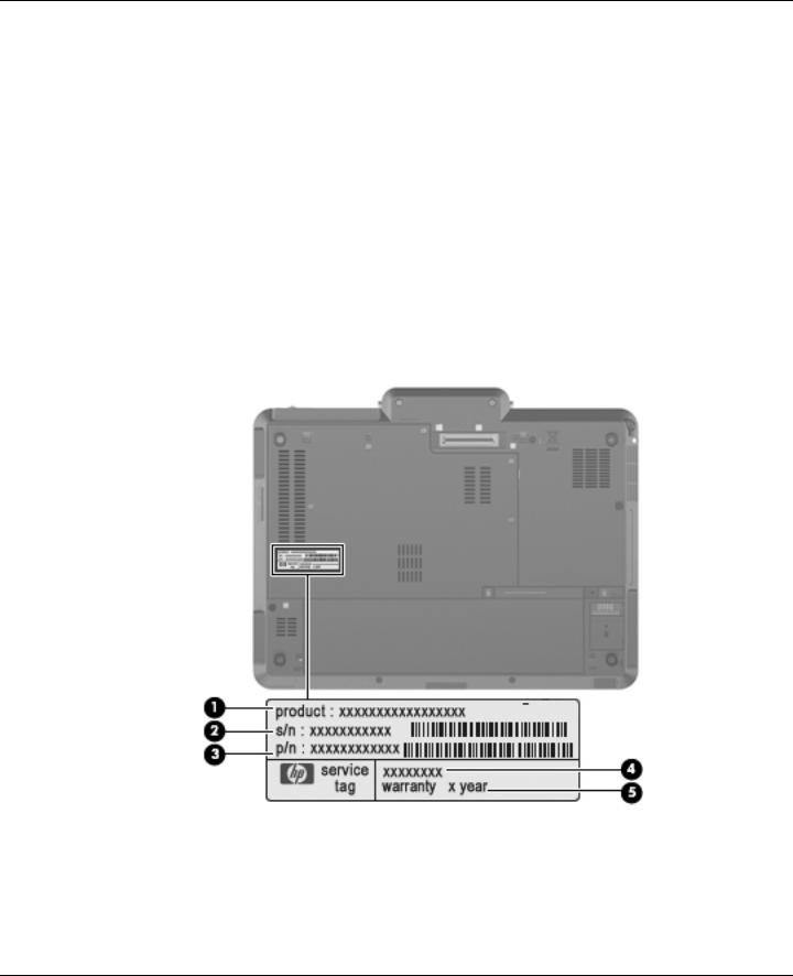
Serial number location
The service tag, affixed to the bottom of the computer, provides information that may be needed when troubleshooting system problems. The service tag provides the following information:
1 Product name: This is the product name affixed to the front of the computer.
2 Serial number (s/n): This is an alphanumeric identifier that is unique to each product.
3 Part number/Product number (p/n): This number provides specific information about the product's hardware components. The part number helps a service technician to determine what components and parts are needed.
4 Model description: This is the number used to locate documents, drivers, and support for the computer.
5 Warranty period: This number describes the duration of the warranty period for the computer.
When ordering parts or requesting information, provide the computer serial number and model description provided on the service tag.
Maintenance and Service Guide |
3–1 |
 NK676UCABA, NL162UPABA User Manual")
Illustrated parts catalog
Computer major components
3–2 |
Maintenance and Service Guide |

Illustrated parts catalog
Item Description |
Spare Part Number |
(1)Display assembly (includes ambient light sensor, fingerprint reader, logo, 2 microphones, nameplate, 2 WLAN antenna transceivers and cables, and 2 WWAN antenna transceivers and cables)
|
12.1-inch, WXGA LED display assembly with webcam and outdoor light |
504172-001 |
|
12.1-inch, WXGA LED display assembly with webcam |
504170-001 |
|
12.1-inch, WXGA LED display assembly with outdoor light |
504171-001 |
|
12.1-inch, WXGA LED display assembly |
504169-001 |
|
|
|
(2) |
Keyboard (includes keyboard cable) |
|
|
For use in Belgium |
501493-A41 |
|
For use in Brazil |
501493-201 |
|
For use the Czech Republic |
501493-211 |
|
For use in Denmark |
501493-081 |
|
For use in Finland and Sweden |
501493-B71 |
|
For use in France |
501493-051 |
|
For use in French Canada |
501493-121 |
|
For use in Germany |
501493-041 |
|
For use in Greece |
501493-DJ1 |
|
For use in Hungary |
501493-221 |
|
For use in Iceland |
501493-DD1 |
|
For use in Israel |
501493-BB1 |
|
For use in Italy |
501493-061 |
|
For use in Japan |
501493-291 |
|
For use in Latin America |
501493-161 |
|
For use in the Netherlands |
501493-B31 |
|
For use in Norway |
501493-091 |
|
For use in Portugal |
501493-131 |
|
For use in Russia |
501493-251 |
|
For use in Saudi Arabia |
501493-171 |
|
For use in Slovakia |
501493-231 |
|
For use in Slovenia |
501493-BA1 |
|
For use in South Korea |
501493-AD1 |
|
For use in Spain |
501493-071 |
|
For use in Switzerland |
501493-BG1 |
|
For use in Taiwan |
501493-AB1 |
|
For use in Thailand |
501493-281 |
|
For use in Turkey |
501493-141 |
|
For use in the United Kingdom |
501493-031 |
|
For use in the United States |
501493-001 |
(Continued)
Maintenance and Service Guide |
3–3 |

Illustrated parts catalog
Item |
Description |
Spare Part Number |
|
|
|
|
Plastics Kit, includes: |
501499-001 |
(3a) |
Hinge cover |
|
(3b) |
ExpressCard slot bezel |
|
(3c) |
Hard drive cover (includes 6 captive screws, secured by C-clips) |
|
|
See “Plastics Kit” on page 3-9 for more Plastics Kit spare part information. |
|
(4) |
Top cover (includes LED board and cable and display alignment guides) |
501502-001 |
|
|
|
(5) |
RTC battery (includes double-sided tape) |
482963-001 |
|
|
|
(6) |
Audio connector board (includes cable) |
507056-001 |
|
|
|
(7) |
Bluetooth module |
483113-001 |
|
The Bluetooth module spare part kit does not include a Bluetooth module cable. The |
|
|
Bluetooth module cable is included in the Cables Kit, spare part number 501500-001. |
|
(8) |
Speaker |
507057-001 |
|
|
|
(9) |
Modem module (includes module cable): |
|
|
For use only in Australia and New Zealand |
461750-011 |
|
For use in all countries and regions except Australia and New Zealand |
461750-001 |
|
|
|
(10) |
System board (includes replacement thermal material) |
|
|
For use in all countries and regions except for Russia and the People’s Republic of China |
|
|
■ Equipped with Intel Core2 Duo SL9600 2.13-GHz processor, 1066-MHz FSB, and |
530589-001 |
|
6-MB L2 cache |
|
|
■ Equipped with Intel Core2 Duo SL9400 1.86-GHz processor, 1066-MHz FSB, and |
501483-001 |
|
6-MB L2 cache |
|
|
■ Equipped with Intel Core2 Duo SL9300 1.60-GHz processor, 1066-MHz FSB, and |
501482-001 |
|
6-MB L2 cache |
|
|
■ Equipped with Intel Core2 Duo SU9400 1.40-GHz processor, 800-MHz FSB, and |
530590-001 |
|
3-MB L2 cache |
|
|
■ Equipped with Intel Core2 Duo SU9300 1.20-GHz processor, 800-MHz FSB, and |
501481-001 |
|
3-MB L2 cache |
|
|
|
|
|
For use in Russia and the People’s Republic of China |
|
|
■ Equipped with Intel Core2 Duo SL9600 2.13-GHz processor, 1066-MHz FSB, and |
598660-001 |
|
6-MB L2 cache |
|
|
■ Equipped with Intel Core2 Duo SL9400 1.86-GHz processor, 1066-MHz FSB, and |
510371-001 |
|
6-MB L2 cache |
|
|
■ Equipped with Intel Core2 Duo SL9300 1.60-GHz processor, 1066-MHz FSB, and |
510370-001 |
|
6-MB L2 cache |
|
|
■ Equipped with Intel Core2 Duo SU9400 1.40-GHz processor, 800-MHz FSB, and |
598661-001 |
|
3-MB L2 cache |
|
|
■ Equipped with Intel Core2 Duo SU9300 1.20-GHz processor, 800-MHz FSB, and |
510369-001 |
|
3-MB L2 cache |
|
|
|
|
(11) |
Fan/heat sink assembly (includes replacement thermal material) |
501495-001 |
|
|
|
(12) |
Base enclosure (includes display release latch and rubber feet) |
501501-001 |
|
Rubber Kit (not illustrated; includes 4 rubber feet, 5 Mylar screw covers, and 2 display |
501496-001 |
|
alignment guides) |
|
|
|
|
(13) |
6-cell, 4.4-Wh battery |
534060-291 |
|
|
|
(14) |
Shield Kit, includes system board shield (not illustrated) and wireless compartment shield |
501503-001 |
(Continued)
3–4 |
Maintenance and Service Guide |

|
|
|
Illustrated parts catalog |
|
|
|
|
|
Item |
Description |
Spare Part Number |
|
|
|
|
(15) |
WLAN module: |
|
|
|
|
|
|
|
|
Intel Wi-Fi Link 5100 802.11a/b/g WLAN module for use in all countries and regions |
482957-001 |
|
|
|
|
|
|
Intel Wi-Fi Link 5100 802.11a/b/g/n WLAN module for use in Russia, Ukraine, and Pakistan |
506678-001 |
|
|
|
|
|
|
Intel Wi-Fi Link 5100 802.11a/b/g/n WLAN module for use in all countries and regions |
480985-001 |
|
|
|
|
|
|
Broadcom 4322 802.11a/b/g/n WLAN module for use in Antigua and Barbuda, Barbados, |
487330-001 |
|
|
Belize, Canada, the Cayman Islands, Guam, Puerto Rico, Trinidad and Tobago, |
|
|
|
the U.S. Virgin Islands, and the United States |
|
|
|
|
|
|
|
Broadcom 4322 802.11a/b/g/n WLAN module for use in Afghanistan, Albania, Algeria, |
487330-002 |
|
|
Andorra, Angola, Antigua and Barbuda, Argentina, Armenia, Aruba, Australia, Austria, |
|
|
|
Azerbaijan, the Bahamas, Bahrain, Bangladesh, Barbados, Belarus, Belgium, Belize, Benin, |
|
|
|
Bermuda, Bhutan, Bolivia, Bosnia and Herzegovina, Botswana, Brazil, |
|
|
|
the British Virgin Islands, Brunei, Bulgaria, Burkina Faso, Burundi, Cameroon, Cape Verde, |
|
|
|
the Central African Republic, Chad, Chile, the People's Republic of China, Colombia, |
|
|
|
Comoros, the Congo, Costa Rica, Croatia, Cyprus, the Czech Republic, Denmark, Djibouti, |
|
|
|
Dominica, the Dominican Republic, East Timor, Ecuador, Egypt, El Salvador, |
|
|
|
Equitorial Guinea, Eritrea, Estonia, Ethiopia, Fiji, Finland, France, French Guiana, Gabon, |
|
|
|
Gambia, Georgia, Germany, Ghana, Gibraltar, Greece, Grenada, Guadeloupe, Guatemala, |
|
|
|
Guinea, Guinea-Bissau, Guyana, Haiti, Honduras, Hong Kong, Hungary, Iceland, India, |
|
|
|
Ireland, Israel, Italy, the Ivory Coast, Jamaica, Jordan, Kazakhstan, Kenya, Kiribati, |
|
|
|
Kyrgyzstan, Laos, Latvia, Lebanon, Lesotho, Liberia, Liechtenstein, Lithuania, Luxembourg, |
|
|
|
Macedonia, Madagascar, Malawi, Malaysia, the Maldives, Mali, Malta, the Marshall Islands, |
|
|
|
Martinique, Mauritania, Mauritius, Mexico, Micronesia, Monaco, Mongolia, Montenegro, |
|
|
|
Morocco, Mozambique, Namibia, Nauru, Nepal, the Nether Antilles, the Netherlands, |
|
|
|
New Zealand, Nicaragua, Niger, Nigeria, Norway, Oman, Pakistan, Palau, Panama, |
|
|
|
Papua New Guinea, Paraguay, Peru, the Philippines, Poland, Portugal, |
|
|
|
the Republic of Moldova, Romania, Russia, Rwanda, Samoa, San Marino, |
|
|
|
Sao Tome and Principe, Saudi Arabia, Senegal, Serbia, the Seychelles, Sierra Leone, |
|
|
|
Singapore, Slovakia, Slovenia, the Solomon Islands, Somalia, South Africa, South Korea, |
|
|
|
Spain, Sri Lanka, St. Kitts and Nevis, St. Lucia, St. Vincent and the Grenadines, Suriname, |
|
|
|
Swaziland, Sweden, Switzerland, Taiwan, Tajikistan, Tanzania, Togo, Tonga, |
|
|
|
Trinidad and Tobago, Tunisia, Turkey, Turkmenistan, Tuvalu, Uganda, Ukraine, |
|
|
|
the United Arab Emirates, the United Kingdom, Uruguay, Uzbekistan, Vanuatu, Venezuela, |
|
|
|
Vietnam, Yemen, Zaire, Zambia, and Zimbabwe |
|
|
|
|
|
|
|
Broadcom BCM4312 802.11b/g WLAN module for use in Antigua and Barbuda, Barbados, |
459263-001 |
|
|
Belize, Canada, the Cayman Islands, Guam, Puerto Rico, Trinidad and Tobago, |
|
|
|
the U.S. Virgin Islands, and the United States |
|
(Continued)
Maintenance and Service Guide |
3–5 |

Illustrated parts catalog
Item |
Description |
Spare Part Number |
|
|
|
|
Broadcom BCM4312 802.11b/g WLAN module for use in Afghanistan, Albania, Algeria, |
459263-002 |
|
Andorra, Angola, Antigua and Barbuda, Argentina, Armenia, Aruba, Australia, Austria, |
|
|
Azerbaijan, the Bahamas, Bahrain, Bangladesh, Barbados, Belarus, Belgium, Belize, Benin, |
|
|
Bermuda, Bhutan, Bolivia, Bosnia and Herzegovina, Botswana, Brazil, |
|
|
the British Virgin Islands, Brunei, Bulgaria, Burkina Faso, Burundi, Cameroon, Cape Verde, |
|
|
the Central African Republic, Chad, Chile, the People's Republic of China, Colombia, |
|
|
Comoros, the Congo, Costa Rica, Croatia, Cyprus, the Czech Republic, Denmark, Djibouti, |
|
|
Dominica, the Dominican Republic, East Timor, Ecuador, Egypt, El Salvador, |
|
|
Equitorial Guinea, Eritrea, Estonia, Ethiopia, Fiji, Finland, France, French Guiana, Gabon, |
|
|
Gambia, Georgia, Germany, Ghana, Gibraltar, Greece, Grenada, Guadeloupe, Guatemala, |
|
|
Guinea, Guinea-Bissau, Guyana, Haiti, Honduras, Hong Kong, Hungary, Iceland, India, |
|
|
Ireland, Israel, Italy, the Ivory Coast, Jamaica, Jordan, Kazakhstan, Kenya, Kiribati, |
|
|
Kyrgyzstan, Laos, Latvia, Lebanon, Lesotho, Liberia, Liechtenstein, Lithuania, Luxembourg, |
|
|
Macedonia, Madagascar, Malawi, Malaysia, the Maldives, Mali, Malta, the Marshall Islands, |
|
|
Martinique, Mauritania, Mauritius, Mexico, Micronesia, Monaco, Mongolia, Montenegro, |
|
|
Morocco, Mozambique, Namibia, Nauru, Nepal, the Nether Antilles, the Netherlands, |
|
|
New Zealand, Nicaragua, Niger, Nigeria, Norway, Oman, Pakistan, Palau, Panama, |
|
|
Papua New Guinea, Paraguay, Peru, the Philippines, Poland, Portugal, |
|
|
the Republic of Moldova, Romania, Russia, Rwanda, Samoa, San Marino, |
|
|
Sao Tome and Principe, Saudi Arabia, Senegal, Serbia, the Seychelles, Sierra Leone, |
|
|
Singapore, Slovakia, Slovenia, the Solomon Islands, Somalia, South Africa, South Korea, |
|
|
Spain, Sri Lanka, St. Kitts and Nevis, St. Lucia, St. Vincent and the Grenadines, Suriname, |
|
|
Swaziland, Sweden, Switzerland, Taiwan, Tajikistan, Tanzania, Togo, Tonga, |
|
|
Trinidad and Tobago, Tunisia, Turkey, Turkmenistan, Tuvalu, Uganda, Ukraine, |
|
|
the United Arab Emirates, the United Kingdom, Uruguay, Uzbekistan, Vanuatu, Venezuela, |
|
|
Vietnam, Yemen, Zaire, Zambia, and Zimbabwe |
|
|
|
|
(16) |
HSPDA EV-DO WWAN module |
483377-002 |
|
|
|
(17) |
Hard drive (includes bracket, isolator and connector cable) |
|
|
250-GB, 5400-rpm |
577990-001 |
|
160-GB, 5400-rpm |
509435-001 |
|
120-GB, 5400-rpm |
501491-001 |
|
80-GB, 5400-rpm |
501490-001 |
|
|
|
|
128-GB solid-state drive (includes bracket, isolator and connector cable) |
574995-001 |
|
|
|
|
80-GB solid-state drive (includes bracket, isolator and connector cable) |
501492-001 |
|
|
|
|
Hard drive connector cable (not illustrated) |
504519-001 |
|
|
|
(18) |
Memory module (PC2-6400, 800-MHz, DDR2) |
|
|
4096-MB |
598855-001 |
|
2048-MB |
598858-001 |
|
1024-MB |
598861-001 |
|
|
|
|
Cable Kit (not illustrated, includes audio connector board cable, see “Cable Kit” on page 3-7 |
501500-001 |
|
for more Cable Kit information) |
|
|
|
|
|
Smart card reader (not illustrated) |
501497-001 |
|
|
|
3–6 |
Maintenance and Service Guide |
 Loading...