


S8610U
Table of contents
 Loading...
69-1955-01
®
Automatic Ignition Systems
ANSI Z21.20
S8610U Universal Intermittent
WARNING
Pilot Gas Ignition Control
SUPER TRADELINE
APPLICATION
The SUPER TRADELINE® S8610U Universal
Intermittent Pilot Gas Ignition Control Module is designed
to provide easy field replacement of a wide range of
intermittent pilot ignition modules manufactured by
Honeywell, Robertshaw, Johnson Controls, and others.
The S8610U control provides ignition sequence, flame
monitoring, and safety shutoff for intermittent pilot central
furnaces, residential boilers, and other heating
appliances. The S8610U replaces existing flame
rectification type, intermittent pilot ignition modules with
the following characteristics:
• Single rod (local sense) or two rod (remote sense)
flame sensing
• Non-100 percent shutoff, 100 percent shutoff/lockout,
or 100 percent shutoff/continuous retry
• Natural or LP gas
• Shutoff/lockout times of 15 seconds or longer
• Prepurge configurable to 30 seconds or no prepurge
• Pilot burners with flow rates of 1,500 Btuh or less
• With or without integral damper connector
Table 1 describes the key features of the S8610U control.
Check Table 2 on page 2 before replacing an
existing intermittent pilot control with the S8610U.
If the existing control is not listed, do not use the
S8610U to replace it unless you are certain the
specifications match those of the existing control.
Table 1. S8610U Universal Intermittent Pilot Gas Ignition Control.
Igniter-Sensor
Typ e
Separate
(two rod; remote
flame sensing)
or
Combination
(one rod; local
flame sensing)
Valve Current
Rating
@ 24 Vac
1.0 A Pilot
and
2.0 A Main
Prepurge
Timing
None or 30
seconds
(field
selectable)
Trial fo r
Pilot
Ignition
15 or 90
seconds
(field
selectable)
®
INSTALLATION INSTRUCTIONS
A complete list of the specific Honeywell and other
modules that the SUPER TRADELINE
designed to replace is provided in Table 2 on page 2.
The SUPER TRADELINE® S8610U package contains
complete, easy-to-use instructions, plus the accessories
required to adapt the existing spark cable (Rajah, stud,
nail, or other) to the spark terminal on the control module.
It also help assure proper marking of the wires attached
to the existing control and a label with LED code
information that can be affixed in the appliance.
IMPORTANT
The S8610U control module is not designed to
replace controls with:
— Flame sensing other than by flame rectification
(White Rodgers Cycle-Pilot
thermal sensing)
— Standing pilot appliances
— Direct main burner ignition
The S8610U provides:
• Natural or LP gas
• Pilot burner ignition using an internally generated high
voltage spark
• Flame rectification circuit to monitor flame presence
• Monitoring of 24 Vac, pilot, and main gas valve
• LED indicator for flame presence/strength and system
status/errors
• Vent Damper connection
• Connections for flame reading via standard microammeter.
The S8610U is designed for a wide variety of natural or
liquid propane fueled applications.
Ignition
Sequence
Typ e
Retry Spark and pilot gas ON until lightoff or trial
Ignition Sequence
(After prepurge, if prepurge is
selected)
for ignition ends.
• If established flame is lost, trial for
ignition restarts immediately.
• If pilot fails to light, pilot gas and spark
Off (100% shutoff). After 5 minute delay,
a new trial for ignition is initiated. This
sequence continues until lightoff or “Call
for Heat” is removed.
®
S8610U is
®
, or Robertshaw
Included for use as
needed.
• If initially installed
Integral
Damper
Connector
and powered up
with damper
attached, unit
must always have
a vent damper
connected.
S8610U UNIVERSAL INTERMITTENT PILOT GAS IGNITION CONTROL
For module replacement, the following table indicates the proper Dip Switch settings for Prepurge timing (SW1) and
Trial For Ignition timing (SW2). See “Settings and Adjustments” on page 15 for Dip Switch information.
Table 2. S8610U Replaces These
Modules
Vendor / Model SW1 SW2
Honeywell
S86A1001
S86A1019
S86A1027
S86A1035
S86B1009
S86B1017
S86B1025
S86C1007
S86C1015
S86C1023 OFF ON
S86C1031
S86C1049
S86C1056
S86D1005
S86D1013 OFF ON
S86D1021
S86E1002
S86E1010
S86E1028
S86E1036
S86E1044
S86E1051
S86E1069
S86E1077
S86E1101
S86 E1119
S86E1127
S86F1000
S86F1018
S86F1026
S86F1042
S86F1059
S86F1067
S86F1075
S86F1083
S86F1091
S86G1008
S86G1016
S86G1024 OFF ON
S86G1032
S86G1057
S86G1073
S86H1006
S86H1014 OFF ON
S86H1022
S86H1048
S86H1055
S86H1063 OFF ON
S86H1089
S86H1097
S86H1105
S86H1113 OFF ON
S86H1121 OFF OFF
S86H1139 OFF ON
S86H1147
S90A1005
S90B1003
S90B1011
S860C1000
S860D1009
S860D1017 ON ON
S8600A1001
S8600B1009
S8600B1025
S8600B3005
S8600B3013
S8600C1015
S8600C3003
S8600F1000
S8600F1034
S8600F1042
S8600H1006
S8600H1014 OFF ON
69-1955—01 2
OFF OFF
OFF OFF
OFF OFF
OFF OFF
OFF OFF
OFF OFF
OFF OFF
ON OFF
OFF OFF
OFF ON
OFF OFF
Table 2. S8610U Replaces These
Modules (Continued)
Vendor / Model SW1 SW2
S8600H1022
S8600H1048
S8600H1055
S8600H1063 OFF ON
S8600H1071
S8600H1089
S8600H1097
S8600H1105
S8600H3002
S8600H3010 OFF ON
S8600M1005
S8600M1013
S8600M1021
S8600M2003
S8600M3001
S8600M4009
S8610A1009
S8610B1007
S8610B1015
S8610B1023
S8610B3003
S8610C1005
S8610C1013
S8610C3001
S8610F1008
S8610F1016
S8610F1024
S8610F1032
S8610H1004 OFF ON
S8610H1012 OFF OFF
S8610H1020 OFF ON
S8610H1038
S8610H1046
S8610H1053
S8610H1061 OFF ON
S8610H1079
S8610H1095
S8610H3000
S8610H3018 OFF ON
S8610H3026
S8610M1003
S8610M1011 OFF ON
S8610M1029
S8610M3009
S8610M3017 OFF ON
S8610U1003
S8610U1011
S8620C1003
S8620C1011
S8620H1002 OFF OFF
S8620H1010 OFF ON
S8620H1028 OFF OFF
S8660D1002 ON OFF
S8660D1010 ON ON
S8660J1008
S8660J1016
S8660J1024
S8660K1006
S8660K1014
S8660K1022
S8670D1000
S8670D1018
S8670D1026
S8670D3006
S8670D3014
S8670E1007
S8670E3003
S8670J3002 ON ON
OFF OFF
OFF OFF
OFF OFF
OFF ON
OFF OFF
OFF OFF
OFF OFF
OFF OFF
OFF OFF
OFF OFF
OFF ON
ON OFF
ON ON
ON OFF
Table 2. S8610U Replaces These
Modules (Continued)
Vendor / Model SW1 SW2
S8670J3010
S8670K3000
S8680J1004 ON ON
ON OFF
Johnson Controls
CSA35A-617R
CSA35A-618R
CSA42A-600R
CSA42A-601R
CSA42A-602R
CSA42A-603R
CSA42A-604R
CSA43A-600R
CSA44A-600R
CSA45A-601R
CSA45A-602R
CSA46A-600R
CSA48A-600R
CSA49A-600R
CSA49A-605R
CSA51A-601R
CSA52A-600R
G60AAA-1
G60AAG-1
G60AAG-2
G60AAG-3
G60AAG-4
G60AAG-5
G60AAG-6
G60AAG-7
G60CAA-1
G60CAA-3
G60CAG-1
G60CAG-2
G60CAG-3
G60CAG-4
G60CAG-5
G60CAG-6
G60CAG-7
G60CAG-8
G60CAG-9
G60CBA-1
G60CBA-2
G60CBA-3
G60CBG-1
G60CBG-2
G60CBG-3
G60CBG-4
G60CBG-5
G60CBG-6
G60CBG-7
G60CBG-8
G60CBG-9
G60CBG-10
G60CBG-11
G60CBG-12
G60CBG-13
G60CBG-14
G60CBG-15
G60CBG-16
G60CBG-17
G60CCA-1
G60CCG-1
G60CPG-1
G60DBG-1
G60DCG-1
G60DCG-2
G60DCG-3
G60DCG-4
G60PAG-1
G60PAG-2
G60PAG-3
G60PAG-4
G60PAG-5
G60PAG-6
G60PAJ-1
G60PAK-1
G60PAK-2
G60PFH-1
G60PFH-2
G60PFL-1
G60PFQ-1
G60PVL-1
G60QAG-1
G60QAG-2
G60QAG-3
OFF OFF
OFF OFF
S8610U UNIVERSAL INTERMITTENT PILOT GAS IGNITION CONTROL
Table 2. S8610U Replaces These
Modules (Continued)
Vendor / Model SW1 SW2
G60QAG-4
G60QAK-1
G60QBG-1
G60QBG-2
G60QBG-3
G60QBG-4
G60QBG-5
G60QBG-6
G60QBG-7
G60QBG-8
G60QBG-9
G60QBH-1
G60QBK-1
G60QBK-2
G60QBK-3
G60QBL-1
G60QBL-2
G60QCG-1
G60QCJ-1
G60QCL-1
G60QDG-1
G60QFL-1
G60QGH-1
G60QHL-1
G60QHL-2
G60QJL-1
G60QLG-1
G60QLK-1
G60QPL-1
G60QRH-1
G60QRH-2
G60QRH-3
G60QRL-1
G60QRL-2
G60QRL-3
G60QSL-1
G60QTH-1
G60QTL-1
G60RAG-1
G60RAK-1
G60RBG-1
G60RBG-2
G60RBG-3
G60RBK-1
G60RBK-2
G60RCG-1
G60RCG-2
G60RCJ-1
G60RDG-1
G60RDK-1
G60RGL-1
G60RHL-1
G60RHP-1
G60RPL-1
G60RSL-1
G60TTL-1
G60ZAG-1
G60ZAG-2
G65BBG-1
G65BBG-2
G65BBG-3
G65BBG-4
G65BBG-5
G65BBG-6
G65BBG-7
G65BBG-8
G65BBM-1
G65BBM-2
G65BBM-3
G65BBM-4
G65BCG-1
G65BCM-1
G65BFG-1
G65BFM
G65BKG-1
G65BKG-2
G65BKG-3
G65BKM-1
G65BKM-2
G65BKM-3
G65BLG-1
G65BLG-2
G65DBG
G65DBM-1
G65DBM-2
G65DBM-3
G65DCM-1
G65DFG
G65DFM-1
G65DKG
G65DKM
G65DKM-1
G65DLM-1
G65FBG
G65FFG
G65FKG
OFF OFF
OFF OFF
Table 2. S8610U Replaces These
Modules (Continued)
Vendor / Model SW1 SW2
G66AG-1
G66AG-2
G66BG-1
G66MG-1
G66MG-2
G66NG-1
G67AG-3
G67AG-4
G67AG-7
G67AG-8
G67AG-9
G67AG-10
G67AG-11
G67BG-2
G67BG-3
G67BG-4
G67BG-5
G67MG-1
G67MG-2
G67MG-3
G67MG-4
G67NG-2
G67NG-4
G600AX-1
G600AX-2
G600AX-3
G600AY-1
G600LX-1
G600LX-2
G600LY-1
G600MX-1
G600NX-1
G600RX-1
G670AW-1
G670AW-2
G670GA-1
G770LGA-1
G770LGA-2
G770LGC-1
G770LGC-2
G770LGC-3
G770LGC-4
G770LHA-1
G770LHA-2
G770LHC-1
G770MGA-1
G770MGA-2
G770MGA-3
G770MGC-1
G770MGC-2
G770MGC-3
G770MGC-4
G770MGC-5
G770MGC-6
G770MHA-1
G770MHA-2
G770MHC-1
G770NGA-1
G770NGC-4
G770NGC-5
G770NGC-6
G770NGC-7
G770NHA-1
G770NHC-1
G770RGA-1
G770RHA-1
G770RHA-2
G775RGA-1
G775RHA-1
G775RHA-2
G779 OFF OFF
Y79ABC-1
Y79ABC-2
Y79ABC-3
Y79ABC-4
Y79ABC-5
Y79ABC-6
Y79ABC-7
Y79ABD-1
Y79ABCD-2
Y79BBA-1
Y79BBA-2
OFF OFF
OFF OFF
OFF OFF
OFF OFF
OFF OFF
OFF OFF
OFF OFF
Table 2. S8610U Replaces These
Modules (Continued)
Vendor / Model SW1 SW2
RobertShaw
780-001
780-002
780-003 ON OFF
780-845
780-715
780-735
780-736
780-737
SP715
SP715A
SP735
SP735D
SP735L
USI715U OFF OFF
OFF OFF
OFF OFF
OFF OFF
White-Rodgers
50D49-350
50D49-360
50D49-361 ON OFF
50D49-401 OFF OFF
OFF OFF
Camstat
IPI-24-00 OFF OFF
Fenwal
05-203025-005
05-203026-005
OFF OFF
HSC
1003-3
1003-300
OFF OFF
SPECIFICATIONS
Control Voltage:
Line 24 V (18-30 Vac) 50/60 Hz
Anticipator Setting:
0.1 A plus valve load @ 24 Vac
Trial for Ignition:
See Table 1 on page 1
Prepurge: See Table 1 on page 1
Flame Failure Response Time:
2 seconds maximum
LED:
The green Status LED provides
system status, error codes, and
flame strength when in run
mode.
Typical Gas Control: Honeywell
models VR8204 and VR8304
Operating Temperature:
Minimum ambient temperature
rating is -40°F (-40°C)
Maximum ambient rating when
used with 2.0 A main valve is
165°F (74°C)
Relative Humidity:
0% to 95% non condensing
3 69-1955—01

S8610U UNIVERSAL INTERMITTENT PILOT GAS IGNITION CONTROL
WARNING
WARNING
WARNING
PLANNING THE INSTALLATION
Fire or Explosion Hazard.
Can cause severe injury, death or property
damage.
1. Plan the installation as outlined below.
2. Plan for frequent maintenance as described in
the Maintenance section.
Intermittent pilot systems are used on a wide variety of
central heating equipment and on heating appliances
such as commercial cookers, agricultural equipment,
industrial heating equipment and pool heaters. Some of
these applications may make heavy demands on the
controls, either because of frequent cycling, or because of
moisture, corrosive chemicals, dust or excessive heat in
the environment. In these situations, special steps may be
required to prevent nuisance shutdowns and premature
control module failure. These applications require special
Honeywell review; contact your Honeywell Sales
Representative for assistance.
Review the following conditions that can apply to your
specific installation and take the precautionary steps
suggested.
Frequent Cycling
These controls are designed for use on appliances that
typically cycle three to four times an hour only during the
heating season. In year-round applications with greater
cycling rates, the control module can wear out more
quickly; perform a monthly checkout.
suspended in air, as in some industrial or agricultural
applications, use a NEMA 4 enclosure for the ignition
control module.
Dust or Grease Accumulation
Heavy accumulations of dust or grease can cause
controls to malfunction. Where dust or grease can be a
problem, provide covers for the ignition control module
and the gas control to limit contamination. A NEMA 4
enclosure is recommended for the ignition control module.
Heat
Excessively high temperatures can damage controls.
Make sure the maximum ambient temperature at the
control module does not exceed the rating of the control
module. If the appliance operates at very high
temperatures, use insulation, shielding, and air
circulation, as necessary, to protect the controls. Proper
insulation or shielding should be provided by the
appliance manufacturer; verify proper air circulation is
maintained when the appliance is installed.
INSTALLATION
When Installing This Product…
1. Read these instructions carefully. Failure to follow
them could damage the product or cause a hazardous condition.
2. Check the ratings given in these instructions to
make sure the S8610U module is suitable for your
application.
3. Installer must be a trained, experienced service
technician.
4. After installation is complete, check out operation
as provided in these instructions.
Water or Steam Cleaning
If the control module gets wet, replace it. If the appliance
is likely to be cleaned with water or steam, protect (cover)
the controls and wiring from water or steam flow. Mount
the controls high enough above the bottom of the cabinet
so they do not get wet during normal cleaning procedures.
Use a NEMA 4 enclosure for the ignition control module.
High Humidity or Dripping Water
Dripping water can cause the control module to fail. Never
install an appliance where water can drip on the controls.
In addition, high ambient humidity can cause the gas
control to corrode and fail.
If the appliance is in a humid atmosphere, make sure air
circulation around the controls is adequate to prevent
condensation. Also, regularly check out the system. A
NEMA 4 enclosure is recommended for the ignition
control module.
Corrosive Chemicals
Corrosive chemicals can attack the ignition control
module and gas control, eventually causing a failure. If
chemicals are used for routine cleaning, make sure they
do not reach the controls. Where chemicals are
69-1955—01 4
Fire or Explosion Hazard.
Can cause severe injury, death or property
damage.
1. The ignition control module can malfunction if it
gets wet, leading to accumulation of explosive
gas.
—Never install where water can flood, drip or
condense on the ignition control module.
—Never try to use an ignition control module
that has been wet; replace it.
2. Liquefied petroleum (LP) gas is heavier than air
and will not naturally vent upward.
—Do not operate electric switches, lights, or
appliances until you are sure the appliance
area is free of gas.
Electrical Shock Hazard.
Can cause severe injury, death or property
damage.
Disconnect power supply before beginning wiring
or making wiring connections to prevent electrical
shock or equipment damage.

S8610U UNIVERSAL INTERMITTENT PILOT GAS IGNITION CONTROL
CAUTION
CAUTION
WARNING
1. If a new gas control is to be installed, turn off
the gas supply before starting installation.
Conduct a Gas Leak Test according to the gas
control manufacturer instructions after the gas
control is installed.
2. Wiring errors can cause improper appliance
operation and dangerous conditions such as
bypassing safety features.
Equipment Damage Hazard.
Water can cause equipment damage or
malfunction.
If ignition control module must be mounted where
there is the potential for exposure to water or
moisture, provide a suitable waterproof enclosure.
Maintenance Requirements in Severe Environments
Regular preventive maintenance is important in any
application, but especially so in commercial cooking,
agricultural, and industrial applications because:
• In many such applications, particularly commercial
cooking, the equipment operates 100,000-200,000 cycles
per year. Such heavy cycling can wear out the gas control
in one to two years. A normal forced air furnace, for which
the controls were originally intended, typically operates
less than 20,000 cycles per year.
• Exposure to water, dirt, chemicals, and heat can
damage the ignition control module or the gas control and
shut down the control system. A NEMA 4 enclosure can
reduce exposure to environmental contaminants.
The maintenance program should include regular
checkout of the system as outlined under “Checkout” on
page 15.
Fire or Explosion Hazard.
Can cause severe injury, death or property
damage.
Do not attempt to take the ignition control module
apart or to clean it. Improper reassembly and
cleaning may cause unreliable operation.
Maintenance frequency must be determined individually
for each application. Some considerations are:
• Cycling frequency – Appliances that may cycle more
than 20,000 times annually should be checked
monthly.
• Intermittent use – Appliances that are used seasonally
should be checked before shutdown and again before
the next use.
• Consequence of unexpected shutdown – Where the
cost of an unexpected shutdown would be high, the
system should be checked more often.
• Dusty, wet, or corrosive environment – Since these
environments can cause the controls to deteriorate
more rapidly, the system should be checked more
often.
Any ignition control module should be replaced if it does
not perform properly on checkout or troubleshooting. In
addition, replace any ignition control module if it is wet or
looks like it has ever been wet. Protective enclosures as
outlined under “Planning the Installation” are
recommended regardless of checkout frequency.
Perform Pre-Installation Safety Check
The pre-installation checks described below must be
done before the replacement ignition control module is
installed. If a condition that could result in unsafe
operation is detected, the appliance should be shut off
and the owner advised of the unsafe condition. Correct
any potentially unsafe condition before proceeding with
the installation.
The following safety checklist should be followed in
making the safety inspection:
1. Conduct a Gas Leakage Test of the appliance piping and control system downstream of the shutoff
valve in the supply line to the appliance.
2. Visually inspect the venting system for proper size
and horizontal pitch and determine there is no
blockage or restrictions, leakage or corrosion or
other deficiencies that could cause an unsafe condition.
3. Shut off all gas to the appliance and shut off any
other fuel-burning appliance within the same room.
Use the shutoff valve in the supply line to each
appliance.
4. Inspect burners and crossovers for blockage and
corrosion.
5. Applicable only to warm air heating appliances.
Inspect heat exchangers for cracks, openings or
excessive corrosion.
6. Applicable only to boilers. Inspect for evidence of
water or combustion product leaks.
7. Insofar as is practical, close all building doors and
windows and all doors between the space in which
the appliance is located and other spaces of the
building. Turn on clothes dryers. Turn on any
exhaust fans, such as range hoods and bathroom
exhausts, so they will operate at maximum speed.
Do not operate a summer exhaust fan.
Close fireplace dampers.
If, after completing steps 7 through 12 in this safety
checklist, it is believed sufficient combustion air is
not available, refer to section 1.3.4 of the National
Fuel Gas Code (Z223.1) for guidance.
8. Place in operation the appliance being inspected.
Follow the lighting instructions. Adjust thermostat so
appliance will operate continuously.
a. Determine that the pilot is burning properly and
that main burner ignition is satisfactory by interrupting and reestablishing the electrical supply
to the appliance in any convenient manner.
b. Determine manifold pressure in order to match
input after the new control is installed.
c. Visually determine that main burner gas is burn-
ing properly; i.e., no floating, lifting or flashback.
Adjust the primary air shutter(s) as required.
d. If appliance is equipped with high and low flame
control or flame modulation, check for proper
main burner operation at low flame.
9. Test for spillage at the draft hood relief opening after
five minutes of main burner operation. Use a draft
gauge, the flame of a match or candle, or smoke
from a cigarette, cigar or pipe.
5 69-1955—01
S8610U UNIVERSAL INTERMITTENT PILOT GAS IGNITION CONTROL
CAUTION
10. Return doors, windows, exhaust fans, fireplace
dampers and all other fuel-burning appliances to
their previous conditions of use.
11. Applicable only to warm air heating appliances.
Check both limit controller and fan controller for
proper operation. Limit controller operation can be
checked by temporarily disconnecting the electrical
supply to the blower motor and determining that the
limit control acts to shut off the main burner gas.
12. Applicable only to boilers:
a. Determine that the circulating water pumps are
in operating condition.
b. Test low water cutoffs, automatic feed controls,
pressure and temperature limit controls and
relief valves in accordance with the manufacturer’s recommendations and instructions to
determine they are in operating condition.
Remove Old Ignition Control Module
Disconnect power supply before doing any work on the
unit. Disconnect and tag the wires from the old module.
Remove the old module from its mounting location.
Wire the System
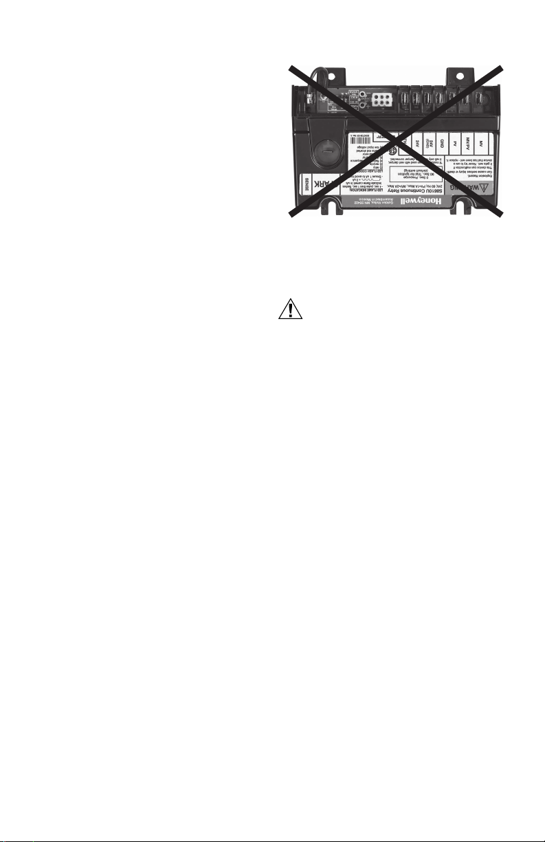
M29889
Fig. 1. Incorrect Mounting.
Mount New Ignition Control Module
The recommended mounting for the S8610U ignition
control module is the same location as the old control
module. Otherwise, select a location close enough to the
burner to allow a short (3 ft. [0.9 m] maximum), direct
cable route to the pilot burner. Ambient temperature at the
control module must be within the range listed in the
“Specifications” on page 3.
Mount the ignition control module with the terminals down
to protect them from dripping water and dust. The control
module can also be mounted with the terminals on either
side. Do not mount with the terminals pointing up. Fig. 1
on page 6 illustrates the incorrect mounting position.
When it is necessary to drill new mounting holes, use the
S8610U as a template to mark the mounting hole pattern.
Drill new holes, as required. Fasten securely with four —
No. 6-32 machine screws, or No. 8 sheet metal screws, or
8-18 x 5/8 Pan Head tapping screws.
Location
The mounting location must provide:
— Good, clear access to the field wiring terminals.
— Operating ambient temperatures between
-40°F (-40°C) and 165°F (74°C).
— Relative humidity below 95% non condensing.
— Protection from water, steam or corrosive chemicals
that are used to clean the appliance.
— Protection from dripping water, such as from an
overfilled humidifier or from condensation.
— Protection from dust or grease accumulation.
IMPORTANT
Do not mount with terminals facing up.
69-1955—01 6
Equipment Damage Hazard.
Disconnect power supply before beginning wiring
or making wiring connections to prevent electrical
shock or equipment damage.
All wiring must comply with local codes and ordinances.
Refer to Fig. 2 and Table 9 on page 11 for typical
connections.
IMPORTANT
1. As shown in the wiring diagrams, a common
ground is required on:
The pilot burner mounting bracket, and the GND
(BURNER) terminal on the ignition control module. Failure to use the GND (BURNER) terminal
may result in intermittent loss of spark and/or
loss of flame current sensitivity.
2. Make sure the transformer has adequate VA.
The ignition control module requires at least
0.1 A at 24 Vac. Add the current draws of all
other devices in the control circuit, including the
pilot and main valves in the gas control, and multiply by 24 to determine the total VA requirement
of these components. Add this total to 2.4 VA (for
the ignition control module). The result is the
minimum transformer VA rating. Use a Class II
transformer if replacement is required.
Connect Vent Damper (Optional)
If the ignition control module is to be used with a damper
connected to the module’s integral damper connector in
an atmospheric appliance, perform the following to
connect it to the module:
IMPORTANT
After the initial power-up, the ignition control
module senses the presence of the vent damper
connection. If the vent damper is connected for
10 ignition cycles, the ignition control module
permanently configures itself to operate only
with the damper connected.
Once an ignition control module completes 10
ignition cycles with a vent damper connected,
the module will not function without a vent
damper being connected.

S8610U UNIVERSAL INTERMITTENT PILOT GAS IGNITION CONTROL
CAUTION
1. Using the wiring harness on the appliance, insert
the matching 6-pin plug into the connector (labeled
P1; see Fig. 2 on page 11) on the S8610U ignition
control module and connect the other end to the
vent damper.
NOTE: The connector (P1) accepts a Molex 03-06-2061
plug.
Connect Ignition Cable
Use existing ignition cable if it is in good condition. If the
existing ignition cable does not have a 1/4 in. quick
connect on the module end, either use the Rajah adapter
or strip the wire and replace with the 1/4 in. insulated
quick connect supplied. If the cable must be replaced,
order a Honeywell ignition cable (Table 3) or refer to Table
4. It might be necessary to replace the connector at the
pilot burner end to match the pilot burner spark
termination.
NOTE: When using an S8610U to replace an S86, use
the enclosed adapter to convert the S86 Ignition
Cable to an S8610U Ignition Cable. Then, install
the adapter and cable to the S8610U Ignition
Module.
Table 3. Honeywell Pre-assembled Ignition Cables
CABLE
PAR T
NUMBER LENGTH
394800-30 30 inches 1/4 inch quick
394801-30 30 inches 1/4 inch quick
(UL Style 3257).
MODULE
END PILOT BURNER
connect,
insulated
connect,
insulated
Rajah connector
receptacle, 90
degree rubber boot
Rajah connector
receptacle, straight
rubber boot
Connect Ignition Control Module
Equipment Damage Hazard.
Check the wiring diagram provided on the
appliance and compare with Table 5 through Table
8 beginning on page 8. Carefully follow any
special instructions affecting the general wiring
procedures outlined in this section.
1. Connect the wires to the module as shown in the
wiring tables (Table 5 through Table 8). Make sure
that adequate system ground is provided as indicated in the wiring tables.
(Refer to Fig. 2 and Table 9 on page 11 for wiring
connections on the S8610U module.)
2. Verify the thermostat anticipator setting as
explained in the Important notes in the wiring tables.
NOTE: Refer to Fig. 2 and Table 9 on page 11 for the
location of each connection on the S8610U module.
The wiring diagrams in Fig. 3 through Fig. 5 beginning on
page 12 describe typical hookups with the S8610U
module and should be used for reference only.
• Fig. 3 shows a basic circuit used only for heating
systems with atmospheric burners and damper control.
(Shown with local and remote flame sensing.)
• Fig. 4 shows a basic circuit used only for heating
systems with atmospheric burners without damper
control. (Shown with local and remote flame sensing.)
• Fig. 5 shows a circuit for power assisted combustion
applications.
Table 4. Recommended Ignition Cable for Field
CABLE TYPE
UL Style 3217 10,000 302°F (150°C)
UL Style 3257 10,000 484°F (250°C)
Cable must be no longer than 36 in. (0.9 m). Solid
conductor cable recommended. To construct a cable, fit
one end of ignition cable with 1/4 in. diameter Rajah
connector receptacle and the other with a 1/4 in. female
quick connect. Protect both ends with insulated boots.
NOTE: The cable must not run in continuous contact
with a metal surface or spark voltage may be
greatly reduced. Use ceramic or plastic standoff
insulators as required. Resistive spark cable
reduces spark voltage and may impact appliance
performance.
Assembly.
VOLTAGE RATING
(rms)
TEMPERATURE
RATING
To install:
1. Connect one end of the cable to the male quick
connect SPARK terminal on the ignition module.
2. Connect the other end of the cable to the igniter or
igniter-sensor stud on the pilot burner/ignitersensor.
7 69-1955—01

S8610U UNIVERSAL INTERMITTENT PILOT GAS IGNITION CONTROL
The following four tables describe the wiring connections necessary for conversion:
Table 5. Conversion from Honeywell Intermittent Pilot Modules.
Replacement
Control Old Control
S90A,B
S8600A,B,C
S8610A,B,C
S8610U1003
S8620C,
Ter min al
Function
Main Valve
Operator
Main Valve
and Pilot
Common
Pilot Valve
Operator
Burner
Ground
Connection
Transformer
Secondary
(unswitched
leg)
Transformer
Secondary
(switched
leg)
Flame
Sensor
Igniter /
Sensor
a
Terminals may be marked 25V on some models and 24V on later models. These are functionally equivalent.
b
If 25V (2) and TH-R have wires connected, disconnect and splice together with solderless connector.
c
If TH-R and TH-W are jumpered together, connect 25V (2) lead from S86 to TH-W on S8610U.
d
On dual igniter and sensor models, remove jumper wire quick connect from S8610U Remote Sense terminal, then cut
jumper wire at circuit board and discard.
e
Leave black jumper connected.
f
Use Rajah to quick connector adapter (supplied) or cut Rajah connector off ignition cable at module end and attach
insulated quick connect for connection to S8610U.
MV
MV/PV MV/PV MV/PV MV/PV MV/PV MV/PV —
PV PV PV PV PV PV —
GND
(BURNER)
24V GND
24V *25V (2) 25V
TH-W
d
SENSE
SPARK
MV
GND GND GND
25V (2)
b
TH-R
c
TH-W
e
IGN COIL
f
MV
MV
(BURNER)
25V
TH-R
TH-W
ee
25V (2)
25V (2) a *24V * 24V *
25V (2) or 24V used only in systems where plug-in
cable connects damper to module
b
TH-R
TH-W
b
c
IGN COIL fIGN COIL fSPARK
S8660D,J
S8670D,J
S8680D,J
MV
GND (BURNER) GND (BURNER) —
a
24V GND
TH-W
(This terminal is
not included on
S90.)
de
SENSE
S8600F,H,M
S8610F,H,M
S8660E,K
S8670E,K
MV
24V GND
TH-W
Procedural NotesS8610U S86A,C S86B,D S86E,F,G,H
—
—
* IMPORTANT
If the old module had a
vent damper connector but
a vent damper was not
installed, or if it did not
have a vent damper
connector, then connect
the 25V (2) or 24V wire
from the old module to the
TH-W terminal on the
S8610U. Do not use the
24V terminal on the
S8610U.
If the old module had a
vent damper, connect it to
the P1 connector on the
module, and wire the
terminals as indicated in
the table.
—
SPARK
—
69-1955—01 8
Loading...