


SV9501/SV9502/SV9601/SV9602
SmartValveTM System Control
|
INSTALLATION INSTRUCTIONS |
APPLICATION |
Carefully determine the full Honeywell model |
|
IMPORTANT |
The Honeywell TRADELINE® SmartValveTM System |
number of the existing control. Use Table 4 or |
Table 5 to make sure the replacement control |
|
Controls provide easy field replacement of a wide range |
model is suitable for replacing the original |
of SV9500, SV9501, SV9502 and SV9602 SmartValveTM |
control. If the control is not suitable, obtain the |
System models. Gas appliance manufacturers use these |
correct TRADELINE® replacement control as |
models in many types of gas fired heating appliances |
shown in Table 4 or Table 5, or contact the |
including central furnaces, residential boilers, rooftop |
appliance manufacturer for the proper |
furnaces, commercial cooking appliances, and unit |
replacement control. |
heaters. These TRADELINE® controls provide |
|
intermittent pilot gas ignition sequencing, pilot flame |
INSTALLATION |
sensing, and both pilot and main gas control functions in |
|
a single control. They are directly compatible with the |
|
Q3450 or Q3480 Intermittent Pilot burners used with the |
When Installing this Product… |
original controls on the appliance. |
|
The TRADELINE® SV9501 and SV9502 SmartValveTM |
1. Read this instructions carefully. Failure to follow |
the instructions as written can damage the product |
|
models are replacement controls only for the SV9500, |
or cause a hazardous situation. |
SV9501, and SV9502 models noted in Table 5. Do not |
2. Check the relevant chart and the ratings given in |
use these controls to replace other types of intermittent |
these instructions and on the specific model to |
pilot or direct ignition controls. Do not use these controls |
make sure the product is suitable for the |
to replace SmartValveTM models not listed in the |
application. |
Replacement table. The controls might fit, but the gas |
3. Installer must be a trained, experienced, licensed |
flow control functions might not be compatible with the |
(if required by local ordinance) technician. |
appliance. |
4. Use these instructions to check product operation |
The TRADELINE® SV9602 SmartValveTM models are |
after completing installation. |
|
|
replacement controls only for the SV9500P, SV9501P, |
IMPORTANT |
SV9502P, SV9600P and SV9601P models noted in Table |
Make sure the control being replaced is |
5. The SV9602 is a prepurge, step-opening model. |
defective. See Fig. 13 through 16 for SV9500, |
IMPORTANT |
SV9501, and SV9502 Sequence of Operation |
and Troubleshooting procedures. |
|
Do not use these controls to replace |
|
SmartValveTM models not listed in the |
Planning the Installation |
replacement table. |
|
Prepurge is nominally 30 seconds. |
WARNING |
The step opening function provides a timed step outlet |
|
pressure at the start of each heating cycle to allow main |
Fire or Explosion Hazard. |
burner ignition at reduced outlet pressure. |
Can cause severe injury, death or property |
|
damage. |
Reducer bushings are provided with the SV9602 and |
Follow these warnings exactly as written. |
SV9601 models for adapting to smaller pipe sizes. |
1. Plan the installation as outlined in this section. |
|
|
|
2. Plan for frequent maintenance as described in |
|
the Maintenance section of this manual. |
|
Intermittent pilot systems used on heating equipment in |
|
barns, greenhouses, and commercial properties, and on |
|
heating appliances such as commercial cookers, |
|
agricultural equipment, and pool heaters make heavy |
69-1270-3
SV9501/SV9502/SV9601/SV9602 SMARTVALVETM SYSTEM CONTROL
demands on the controls. Special steps are recommended to prevent nuisance shutdowns and control failures due to frequent cycling, or severe environmental conditions such as exposure to moisture, corrosive chemicals, dust, or excessive heat. Following are the possible causes of shutdown and the preventative solutions.
Frequent Cycling
These controls are designed to cycle three to four times each hour during the heating season. Year around applications and applications with more frequent cycling rates can wear out controls more quickly than normal operation. Perform monthly system checks to make sure the system operates properly.
Water or Steam Cleaning
Replace any electronic control that gets wet. If the appliance is likely to be cleaned with water or steam, cover the control and wiring to protect them from water or steam flow. Mount the control high enough above the cabinet bottom to avoid getting it wet during cleaning procedures.
Installation
 WARNING
Fire or Explosion Hazard.
Can cause severe injury, death or property damage.
Follow these warnings exactly as written.
1.Disconnect the power supply before wiring to prevent electrical shock and equipment damage.
2.Turn of the gas supply at the appliance service valve before starting installation to avoid dangerous accumulation of fuel gas.
3.Perform gas leak test after completing installation.
4.Do not bend pilot tubing at ignition system control or pilot burner after tightening the compression fitting. Bending can cause gas leakage at the connection.
5.Always install a sediment trap in the gas supply line to prevent contamination of the ignition system.
High Humidity or Dripping Water
Dripping water can cause the control to fail. Never install an appliance where water can drip on the control. High humidity around the control can cause the control to corrode and fail. If the appliance is located in a humid atmosphere, make sure the air circulation around the control is adequate to prevent water condensing on the control. Check the system regularly for signs of condensation and corrosion.
Corrosive Chemicals
Corrosive chemicals can erode the control, eventually causing a failure. If chemicals are used for routine cleaning, make sure they do not touch the control. Where chemicals are suspended in air, for example, in some industrial or agricultural applications, protect the control with an enclosure.
Dust or Grease Accumulation
Heavy accumulations of dust or grease can cause the control to malfunction. Where dust or grease are problems, cover the control to limit contamination.
 WARNING
Fire or Explosion Hazard.
Can cause severe injury, death or property damage.
Follow this warning exactly as written.
•Always change the main and pilot burner orifices when converting between LP and natural gas. Follow appliance manufacturer specifications and instructions.
 CAUTION
Equipment Damage Hazard.
Improper device replacement will damage the equipment.
The SV9501, SV9502, SV9602, and SV9601 provide direct replacement only as shown in Table 4 or Table 5 of this manual. Use the Y8610 to convert standing pilot systems to electronic ignition systems.
Heat
Excessively high (above 175°F [79°C]) temperatures can damage the control. Make sure the ambient temperature at the control does not exceed the control rating. If the appliance operates at very high temperatures, use insulation, shielding and proper air circulation as necessary to protect the control. The appliance manufacturer should provide proper insulation or shielding. Make sure there is proper air circulation when installing the appliance.
 CAUTION
Equipment Damage Hazard.
Can Burn Out Heat Anticipator in Thermostat.
1.Never apply a jumper across or short the terminals in the SV9501, SV9502, SV9602, or SV9601 connectors or appliance wiring harnesses.
2.Never short the electric fan timer (EFT) output. Shorting the output can damage the EFT drive circuitry.
IMPORTANT
These ignition system controls are shipped with protective seals over inlet and outlet tappings. Do not remove seals until ready to connect piping.
Follow the appliance manufacturer’s instructions if available. Otherwise, use these instructions as a guide.
69-1270—3 |
2 |
SV9501/SV9502/SV9601/SV9602 SMARTVALVETM SYSTEM CONTROL
Ignition system controls are set at the factory for natural or LP gas. Do not attempt to use an ignition control made for LP gas on a natural gas system. Do not attempt to use an ignition control made for natural gas on an LP gas system.
Ignition system controls with standard opening regulators (SV9501M, SV9502M, and SV9601M) or slow opening regulators (SV9501H and SV9502H) can be converted between natural gas and LP gas.
Ignition system controls with step opening regulators (P suffix) cannot be converted between gases.
Use of Pipe Adapters
In some field service applications, space limitations make it difficult or impossible to thread the gas control onto the gas supply line. This problem can be resolved for many installations by using a pipe adapter. Install the pipe adapter on the end of the supply line in place of the gas control by following the same precautions and instructions that are used for installing the gas control. After the pipe adapter is installed, attach the gas control to the adapter.
NOTE: Using a pipe adapter increases the overall length of the gas control.
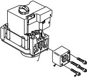
Selecting the Valve
Make sure when replacing any SmartValveTM that you know what valve is going in and what valve is coming out. The SV9501 and SV9502 look slightly different from the SV9500. The SV9500 features an ON/OFF control knob, as shown in Fig. 1. The SV9501, SV9502, SV9602, and SV9601 have an ON/OFF switch, as shown in Fig. 2. The SV9501, SV9502, SV9601, and SV9602 have a connector located at the top of the valve instead of on the front.
The SV9501, SV9502, SV9602, and SV9601 have identical valve body features and use the same connectors.
NOTE: The SV9601 and the SV9602 do not have flange mounting capability.
VALVE OUTLET
FLANGE 
9/64 INCH HEX SCREWS (4) M3342A
Fig. 1. Front view of SV9500. Notice the ON/OFF control knob.
Location
Mount the SV9501, SV9502, SV9602, or SV9601 on the gas manifold in the appliance.
Install Pipe Adapter to Gas Control
Install adapter to gas control as follows:
Bushings
1.Remove seal over gas control inlet or outlet.
2.Apply moderate amount of good quality pipe compound to bushing, leaving two end threads bare.
3.Insert bushing into gas control and carefully thread pipe into the bushing until tight.
Installing Flange Adapters to Control (If Required)
Mount any necessary adapters as follows:
Flanges
1.Choose the correct flange for the application.
2.Remove the seal over the ignition system control or outlet.
3.Make sure the O-ring is fitted in the flange groove. If the O-ring is not attached or is missing, do not use the flange.
4.With the O-ring facing the ignition system control, align the screw holes on the ignition system control with the holes in the flange.
5.Insert the screws provided with the flange.
6.Tighten the screws firmly but do not over tighten
Installing Piping to Control
IMPORTANT
Do not use Teflon® tape.
All piping must comply with local codes or ordinances or with the National Fuel Gas Code (ANSI Z223.1 NFPA No. 54), whichever applies. Tubing installation must comply with approved standards and practices.
1.Use new, properly reamed pipe that has no chips.
2.Make sure the ends are square, deburred, and clean.
3.Make sure all tubing bends are smooth and without deformation.
4.Get a tube-to-pipe coupling if necessary.
5.Run pipe or tubing to the ignition system control.
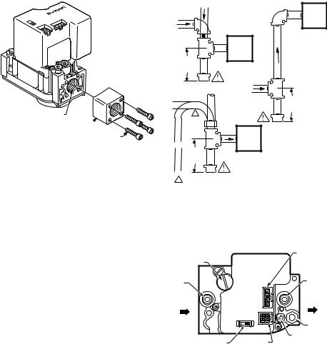
6.Install a sediment trap in the supply line to the ignition system control as shown in Fig. 3.
3 |
69-1270—3 |
SV9501/SV9502/SV9601/SV9602 SMARTVALVETM SYSTEM CONTROL
VALVE OUTLET
FLANGE 
M17142 |
9/64 INCH HEX SCREWS (4) |
Fig. 2. Front view of SV9501 or SV9502. Notice the connectors and the ON/OFF control switch.
Installing the Control
This ignition system can be mounted from 0 to 90 degrees in any direction including vertically from the upright position of the ignition system control switch.
IMPORTANT
Make sure to mount the replacement control in the same location and orientation as the original control.
DROP |
|
|
|
PIPED |
IGNITION |
HORIZONTAL |
GAS |
SYSTEM |
|
CONTROL |
|
|
SUPPLY |
|
|
|
|
|
|
RISER |
|
IGNITION |
|
|
SYSTEM |
PIPED |
|
CONTROL |
|
|
GAS |
|
3 IN. |
|
|
|
SUPPLY |
|
(76 MM) |
|
|
MINIMUM |
|
|
DROP |
|
|
HORIZONTAL |
|
3 IN. |
|
TUBING |
(76 MM) |
|
GAS |
MINIMUM |
1 |
|
|
SUPPLY |
|
|
|
|
|
|
IGNITION |
|
|
SYSTEM |
|
RISER |
CONTROL |
|
3 IN. |
|
|
(76 MM) |
|
|
MINIMUM |
|
|
1 ALL BENDS IN METALLIC TUBING MUST BE SMOOTH.
 CAUTION
Gas Leakage Hazard.
Failure to follow precautions can result in a gas-filled work area. Shut off the main gas supply before removing end cap. Test for gas
leakage when installation is complete. |
M3343C |
Fig. 3. Sediment trap installation.
1.Mount the control so the gas flow is in the direction of the arrow on the bottom of the ignition system control, as shown in Fig. 4.
2.Apply a moderate amount of good quality pipe compound to the pipe, leaving the two end threads bare, as shown in Fig. 5. For LP controls make sure to use an LP resistant pipe compound.
3.Remove the seals over the ignition system control inlet and outlet if necessary.
4.Thread the pipe the amount shown in Table 1. Do not thread the pipe too far, because this could cause valve distortion or malfunction.
5.Using a wrench on the square ends of the ignition system control, connect the pipe to the ignition system control inlet and outlet.
PRESSURE REGULATOR |
IGNITER |
ADJUSTMENT (UNDER |
CONNECTOR |
CAP SCREW) |
|
INLET |
|
|
|
|
PRESSURE |
|
|
OUTLET |
|
TAP |
|
|
|
|
|
|
|
PRESSURE |
|
|
|
|
|
|
|
|
|
IGNITER |
TAP |
INLET |
|
OUTLET |
||
|
|
OFF ON |
CONTROL |
PILOT |
|
|
|
|
OUTLET |
|
IGNITION SYSTEM |
CONTROLS |
PILOT ADJUSTMENT |
|
M7934 |
CONTROL SWITCH |
CONNECTOR |
(UNDER CAP SCREW) |
|
Fig. 4. Mount so gas flows in the direction of the arrows.
NOTE: If the control has a flange, place the wrench on the flange instead of on the ignition system control, as shown in Fig. 6.
Table 1. Threading the Pipe.
|
Thread Pipe |
Maximum Depth Pipe |
|
can be Inserted into |
|
Pipe Size |
this Amount |
Control |
3/8 in. |
9/16 in. |
3/8 in. |
|
|
|
1/2 in. |
3/4 in. |
1/2 in. |
|
|
|
3/4 in. |
13/16 in. |
3/4 in. |
|
|
|
69-1270—3 |
4 |

SV9501/SV9502/SV9601/SV9602 SMARTVALVETM SYSTEM CONTROL
TWO |
IGNITION |
IMPERFECT |
SYSTEM |
THREADS |
CONTROL |
PIPE |
THREAD PIPE THE AMOUNT |
APPLY A MODERATE AMOUNT OF |
SHOWN IN TABLE FOR INSERTION |
PIPE COMPOUND ONLY TO PIPE |
INTO IGNITION SYSTEM CONTROL |
(LEAVE TWO END THREADS BARE). |
|
M3344 |
Fig. 5. Use a moderate amount of pipe compound.
Connecting the Pilot Gas Tubing
NOTE:
1.The pilot tubing provides the SmartValveTM system’s flame sense current path. Make sure the connections are clean and tight.
2.Do not make sharp bends or deform the tubing. Do not bend tubing at the ignition system control after the compression nut is tightened, because this can cause gas leakage.
1.Cut the tubing to the desired length.
2.Bend the tubing as necessary for routing to the pilot burner.
3.Square off and debur the end of the tubing.
4.Unscrew the brass compression fitting from the pilot outlet.
5.Slip the fitting over the tubing and out of the way.
6.Push the tubing into the pilot gas outlet.
7.Tap the outlet end of the control.
8.Remove and discard the old fitting.
9.While holding tubing all the way in, slide the new fitting (included with the new SmartValveTM) into place and begin thread until finger tight as shown in Fig. 7.
10.Tighten fitting one more full turn with the wrench. Do not overtighten.
11.Connect the other end of the tubing to the pilot burner as described in the instructions supplied with Q3450 or Q3480 pilot hardware.
Wiring
Follow the wiring instructions supplied by the appliance manufacturer if available. Otherwise, use the following general instructions.
NOTE:
1.In most cases, connect the wiring by plugging
the appliance wiring harness connector into the SmartValveTM. Use the supplied extension harness if necessary.
2.Where the general instructions are different from the appliance manufacturer’s instructions, use the appliance manufacturer’s instructions.
WHEN FLANGE IS NOT USED |
WHEN FLANGE IS USED |
APPLY WRENCH APPLY WRENCH FROM TOP OR TO FLANGE ONLY BOTTOM OF IGNITION SYSTEM
CONTROL TO EITHER SHADED AREA
M7928
Fig. 6. Proper use of wrench on ignition system control with and without flanges.
 IGNITION SYSTEM CONTROL
TIGHTEN NUT ONE TURN
BEYOND FINGER TIGHT
FITTING BREAKS OFF AND CLINCHES TUBING AS NUT IS TIGHTENED
TO PILOT BURNER
M3346
 CAUTION
Equipment Damage Hazard.
Electrostatic discharge can short equipment circuitry.
Disconnect the power supply before making wiring connections.
Fig. 7. Tighten new fitting and nut. |
IMPORTANT |
All wiring must comply with applicable electrical |
|
Always use a new compression fitting. |
codes and ordinances. |
5 |
69-1270—3 |
 Loading...