


MV100 Electric Controllers
T100, T200 Thermostatic Controllers
and V2000 Radiator Valves
PRODUCT DATA
|
|
APPLICATION |
|
THERMOSTATIC CONTROLS |
|||
The MV100, T100, T200 Controllers, when paired with V2000 |
|||
|
|
||
|
|
Radiator Valves, provide automatic temperature control by |
|
|
|
modulating the flow of steam or hot water through free- |
|
T100 |
T100M |
standing radiators, convectors, and other heating units. They |
|
provide comfort and energy savings at affordable prices. |
|||
|
|
FEATURES |
|
|
|
T100C |
• Continually monitors and adjusts room temperature |
||
T100F |
for consistent comfort and relief from underheating |
|||
|
and overheating. |
|
||
|
|
|
||
|
|
• T100,T200 Controllers include sensor, setpoint dial |
|
|
T100B |
T200 |
and valve actuator; components can be integral or |
|
|
connected by capillary tubing. |
|
|||
|
|
|||
|
|
• T100,T200 Controllers require no electrical |
|
|
|
|
connections. |
|
|
|
|
• T100A,F,M models have range limiting features to limit |
||
|
|
adjustment or lock at a fixed setting (can require limit |
||
MV100 |
|
pin accessory). |
|
|
|
|
• EPDM valve seat disk assures tight shutoff on steam |
||
VALVE BODIES |
and hot water systems. |
|
||
• Nickel-plated bronze cast valve body. |
|
|||
|
|
• Cartridge containing all working parts inserts into |
|
|
|
|
valve body for ease of service. |
|
|
V2043H |
|
• Cartridges are replaceable while valves remain in |
|
|
|
|
service and under pressurE (WITH accessory service |
||
|
|
tool MT100C). |
|
|
|
|
• Valves remain normally open with no control mounted. |
||
|
|
• Valves can be used with T100, T200 Thermostatic or |
||
|
|
MV100 Electric Controllers. |
|
|
|
|
Contents |
||
V2040D |
V2040A |
Application ........................................................................ |
1 |
|
|
Features ........................................................................... |
1 |
||
|
|
Specifications ................................................................... |
2 |
|
|
|
Ordering Information ........................................................ |
2 |
|
|
|
Installation ........................................................................ |
5 |
|
|
|
Wiring (MV100 only) ......................................................... |
9 |
|
|
|
Operation .......................................................................... |
9 |
|
V2040E |
|
Settings and Adjustments ................................................. |
9 |
|
V200LD |
Single-Pipe Steam Applications |
10 |
||
|
||||
|
|
Troubleshooting ................................................................ |
12 |
|
|
|
Pressurized Valve Cartridge Replacement |
13 |
|
|
|
|||
62-3048—2
MV100 ELECTRIC CONTROLLERS T100, T200 THERMOSTATIC CONTROLLERS AND V2000 RADIATOR VALVES
SPECIFICATIONS
MV100 Electric Controller
Dimensions: See Fig. 1.
Materials:
Body: Industrial grade plastics with low thermal conductivity. Fastening Ring: Plated brass.
Internal Parts: Brass thermostat capsule, other metals. Thermal element: Wax-filled brass capsule.
Electrical Ratings:
Control Type: Spst switch. Controller:
Voltage: 24 Vac, 60 Hz, or 24 Vdc. Power Consumption: 0.125A, 3W.
End Switch: Low-voltage (24 Vac, 5A), two-position, spst, normally open switch (closes when controller powered).
Configuration (with Controller Mounted):
Normally closed (valve remains closed without power).
NOTE: Normally open model available in Canada.
Opening Time (at 78°F): Maximum: 5 minutes from cold to fully open.
Ambient Temperature Rating: Maximum: 122°F (50°C).
T100,T200 Thermostatic Controllers
Models: See Table 1.
Dimensions: See Fig. 1.
Power: Self-powered, no electrical connections.
Components: Sensor, setpoint dial and valve actuator.
ORDERING INFORMATION
Materials:
Body: Industrial grade plastic with low thermal conductivity. Fastening Ring: Plated brass.
Internal Parts: Brass thermostat capsule, other metals. Thermal Element:
T100A,M: Wax.
T200,T100B,C,F: Liquid Ethyl Acetate (non-toxic, flammable).
Temperature Ratings:
Range: 43°F to 79°F (6°C to 26°C).
Maximum: 125¼F (52¼C).
V2000 Valves
Models: See Table 2.
Dimensions: See Fig. 2 and 3.
Materials:
Body: Bronze.
V2040A (1/2 in.): Brass. Union: Brass.
Stem Seal: Double EPDM seal.
Cartridge: Brass and stainless steel with EPDM seat disk.
NOTE: Apply 25 ft.-lb. (30 N•m) torque when installing the valve cartridge.
Maximum Temperature Rating: 266°F (130°C).
Maximum Pressure Ratings:
System:
Water: 145 psi (10 bar). Steam: 15 psi (103 kPa).
Differential:
With MV100 Controller: 36 psi (248 kPa). With T100 or T200 Controller: 14.5 psi (1 bar). For Low Noise: 2.9 psi (20 kPa).
Sizes:
V2024H: 1/8 in.
V200LD: 1/2 in., 3/4 in.
V2040D,E,A: 1/2 in., 3/4 in., and 1 in.
When purchasing replacement and modernization products from your TRADELINE® wholesaler or distributor, refer to the TRADELINE® Catalog or price sheets for complete ordering number.
If you have additional questions, need further information, or would like to comment on our products or services, please write or phone:
1.Your local Honeywell Automation and Control Products Sales Office (check white pages of your phone directory).
2.Honeywell Customer Care 1885 Douglas Drive North
Minneapolis, Minnesota 55422-4386
In Canada—Honeywell Limited/Honeywell Limitée, 35 Dynamic Drive, Scarborough, Ontario M1V 4Z9.
International Sales and Service Offices in all principal cities of the world. Manufacturing in Australia, Canada, Finland, France, Germany, Japan, Mexico, Netherlands, Spain, Taiwan, United Kingdom, U.S.A.
62-3048—2 |
2 |

MV100 ELECTRIC CONTROLLERS T100, T200 THERMOSTATIC CONTROLLERS AND V2000 RADIATOR VALVES
T100A
TOP
T100M
TOP
2
(50)
2
(50)
 1 (25)

 2-1/8 (54)
3
(77)
3-5/16
(84)
MAX.
M12925A |
M12929 |
|
T100B
CAPILLARY TUBE LENGTH
2-1/8 (54)
6-1/2 FT (2m) OR 16 FT. (5m)
1-13/16
2-5/32 (46)
(55)
 2-31/32 (75)
M12926
T200A
TOP
1-9/16
(40)
13/16 (20)
3
(76) MAX
T100C
CAPILLARY TUBE LENGTH |
|
|
|
2-1/8 (54) |
|
4-1/2 FT (1.4 m) |
|
|
1-13/16
2-5/32 (46)
(55)
2-31/32 (75)
CAPILLARY TUBE
LENGTH 4-1/2 FT (1.4 m) 
|
M12927 |
T100F |
2-1/8 (54) |
CAPILLARY TUBE |
2 (50) |
|
|
LENGTH 6-1/2 FT (2 m) |
|
|
3-5/16 |
|
(84) |
|
MAX. |
M12928
MV100
 2 (51)
xxxxxxxxBraukmann |
H |
2-7/8
(74)
M3187A
M12945
Fig. 1. MV100, T100 and T200 dimensions in in. (mm).
3 |
62-3048—2 |
MV100 ELECTRIC CONTROLLERS T100, T200 THERMOSTATIC CONTROLLERS AND V2000 RADIATOR VALVES
Table 1. T100,T200 Models.
Model |
Control Range |
Mounting |
Capillary |
Description |
T100A |
43°F to 79°F |
Directa |
None |
Components are in one unit. |
|
(6°C to 26°C) |
|
|
|
T100B |
48°F to 79°F |
Remote |
One 6-1/2 ft (2 m) |
Sensor and setpoint dial combined and remote from valve |
|
(9°C to 26°C) |
|
or 16 ft (5 m) |
actuator. |
T100C |
|
Remote |
Two 4-1/2 ft |
Components mount remotely from each other. |
|
|
|
(1.4 m) |
|
T100F |
43°F to 79°F |
Direct with |
One 6-1/2 ft (2 m) |
Sensor is remote from combination setpoint dial and valve |
|
(6°C to 26°C) |
remote |
|
actuator. |
|
|
sensor. |
|
|
T100M |
|
Directa |
None |
Components are in one tamper-resistant unit. |
T200A |
|
Directa |
None |
White body with chrome-plated end. |
a Mount the unit horizontally on the valve body for accurate temperature regulation.
Table 2. V2000 Models.
|
|
|
Connection |
|
|
|
|
Model |
|
Body Pattern |
Inlet |
Outlet |
|
|
Application |
V2040D |
|
Straight |
NPT |
Union Nut with |
Use where manual valves were not originally installed. |
||
|
|
|
Threaded |
NPT Threaded |
|
|
|
V2040E |
|
Angle |
Typically used with remote temperature sensing controllers. |
||||
|
|
|
|
or Sweat |
|
|
|
V2040A |
|
Horizontal Angle |
|
Typically used with direct-mount controllers (T100A,M; T200A) |
|||
|
|
|
|||||
|
|
|
|
|
|
|
|
V200LD |
|
Straight |
Sweat |
Sweat |
Use with copper tubing installations. |
||
|
|
|
|
|
|
|
|
V2042H/ |
|
One-Pipe |
18 in. NPT |
1/8 in NPT for |
Use in single-pipe steam applications. |
||
V2043H |
|
|
|
SA123A Vent |
|
|
|
|
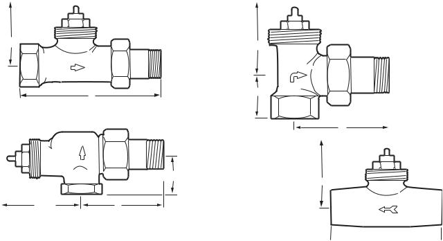
V2040D (Straight Body) |
|
V2040E (Angle Body) |
||||
|
|
|
|
|
|
|
|
B MAX.
B MAX.
A |
C |
|
|
|
M12930B |
V2040A (Horizontal Angle Body)
A
M12931B
V200LD (Straight Body)
C
B MAX.
B MAX. |
A |
M12932B
M12933B  A
A 
Fig. 2. V2000 dimensions.
NOTE: Refer to Table 3 for detailed valve dimensions for each valve size.
62-3048—2 |
4 |
MV100 ELECTRIC CONTROLLERS T100, T200 THERMOSTATIC CONTROLLERS AND V2000 RADIATOR VALVES
Table 3. Valve Dimensions.
|
|
|
|
|
|
Size in |
A |
B Maxa |
C |
Valve |
in. |
in in. (mm) |
in in. (mm) |
in in. (mm) |
V2040D |
1/2 |
3-3/4 (95) |
4-1/16 (104) |
— |
|
3/4 |
4-3/16 (106) |
4-1/16 (104) |
— |
|
|
|
|
|
|
1 |
4-1/2 (114) |
4-1/2 (114) |
— |
|
|
|
|
|
V2040E |
1/2 |
2-5/16 (58) |
3-3/16 (98) |
1 (26) |
|
|
|
|
|
|
3/4 |
2-5/8 (66) |
3-13/16 (98) |
1-1/8 (29) |
|
|
|
|
|
|
1 |
2-15/16 (74) |
4-5/16 (110) |
1-5/16 (34) |
|
|
|
|
|
V2040A |
1/2 |
2-1/8 (54) |
4-1/2 (115) |
1-1/8 (28) |
|
|
|
|
|
|
3/4 |
2-1/2 (64) |
5-3/16 (132) |
1-3/16 (31) |
|
|
|
|
|
|
1 |
2-15/16 (74) |
5-3/16 (132) |
1-7/16 (37) |
|
|
|
|
|
V200LD |
1/2 |
2-5/8 (66) |
4-1/16 (104) |
— |
|
|
|
|
|
|
3/4 |
2-15/16 (74) |
4-1/16 (104) |
— |
|
|
|
|
|
V2042H |
3/8 |
1-11/16 (43) |
3-13/16 (98) |
1-3/16 (31) |
|
|
|
|
|
aB Max dimension is with T100A control installed, except for the V2042H, for which it is without the steam/air vent installed.
Connections:
Inlets Available: Internally threaded.
Sweat (1/2 in. and 3/4 in. only). Outlets Available:
Union nut with threaded tailpiece. Sweat (1/2 in. and 3/4 in. only).
Union nut with sweat tailpiece (1/2 in. and 3/4 in. only).
Capacity:
Cv (gpm at 1 psi drop across fully-open valve): 1/2 in.: 2.0.
3/4 in.: 2.2. 1 in.: 2.3.
Btuh (Btu/hr at 7 psi drop across fully-open valve): 1/2 in.: 59,100.
3/4 in.: 63,800. 1 in.: 70,500.
Accessories:
203225 Replacement Bulb Guard for T100F.
272844 Locking Cap and Limit Pins for T100M.
272873 MT100C Cartridge Tool Driver Upgrade Kit. A104F Limit Pins for T100A,F.
VS1200SL01 Replacement Valve Cartridge. G111B Bulb Guard to protect T100C sensor when
wall-mounted.
VA8200A001 Valve Cartridge Replacement Tool for system under pressure (V2000).
Q110D Inlet Strainer Inserts for NPT V100 (models available for 1/2 in. and 3/4 in. valves).
SA123A Steam/Air Vent for V2042HSL10 One-pipe Steam Valve.
 B MAX.
 A
A 


 0 6 5
0 6 5


C
M17016
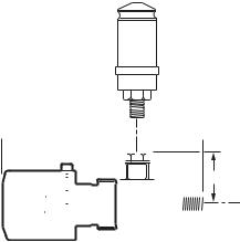
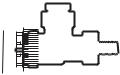
Fig. 3. V2042H (Body)/V2043H (Body with Airstream Vent) Dimensions.
NOTE: Refer to Table 3 for detailed valve dimensions for each valve size.
INSTALLATION
When Installing this Product...
1.Read these instructions carefully. Failure to follow them could damage the product or cause a hazardous condition.
2.Check the ratings given in the instructions and on the product to make sure the product is suitable for your application.
3.Installer must be a trained, experienced service technician.
4.After installation is complete, check out product operation as provided in these instructions.
 CAUTION
Equipment Damage Hazard.
Excessive force can distort and damage valve.
Do not overtighten the union nut.
 CAUTION
Equipment Damage Hazard.
Driving an unmounted MV100 can damage the actuator beyond repair.
Mount the MV100 before applying power to the actuator.
 CAUTION
Sweat Valve Damage Hazard.
Soldering the valve with the cartridge or controller attached can damage the device.
Prior to attaching valve to piping, remove controller and cartridge from potential exposure to heat.
IMPORTANT
When installing the valve body, ensure that the arrow (cast into the body) points in the direction of the flow.
5 |
62-3048—2 |
 Loading...