


 Loading...
ST9120B,U
Universal Electronic Fan Timers
INSTALLATION INSTRUCTIONS
APPLICATION |
On/Off Delay Settings: |
|
The ST9120B,U Universal Electronic Fan Timers integrate control of all combustion blower and circulating fan operations in a gas warm air appliance. This control is the central wiring point for most of the electrical components in the furnace. The basic purposes of the ST9120B,U are to monitor the thermostat for heat, cool and fan demands, run the induced draft blower motor and run a circulating fan (up to two speeds) as required. The ST9120B,U also monitors limit switch strings and energizes separate ignition control systems through pressure switches. The ST9120B,U can replace any ST9101, ST9120, ST9141 or ST9160 listed in Table 3 below. The ST9120B,U features a field-adjustable heat fan-on delay, a field-adjustable heat fan-off delay, a fieldadjustable cool fan-on delay and a field-adjustable cool fan-off delay.
Electronic air cleaner (EAC) and humidifier (HUM) convenience terminal connections and continuous low speed indoor air circulation are provided.
SPECIFICATIONS
Electrical Ratings:
Power Voltage Requirements: 18 to 30 VAC, 50/60 Hz.
Contact Ratings: Combustion Blower:
1.5A full load, 10A locked rotor at 115 VAC.
0.75A full load, 5A locked rotor at 230 VAC. (Reduce full load rating by humidifier [HUM] load.)
Circulating Fan: Heat-Cool speed:
15A full load, 30A locked rotor at 115 VAC.
7.5A full load, 15A locked rotor at 230 VAC.
(Reduce full load rating by electronic air cleaner [EAC] load.)
Continuous speed (optional):
8A full load, 16A locked rotor at 115 VAC.
4A full load, 8A locked rotor at 230 VAC. EAC and HUM:
0.8A maximum combined load at 115 VAC
0.4A maximum combined load at 230 VAC Thermostat W Load: 100mA at 24 VAC, plus ignition sys-
tem load.
Thermostat G, Y, Primary Limit, Burner Limit, Pressure Switch Load: 22mA at 24 VAC load/cleaning current.
NOTE: Timing is derived from 24 VAC supply frequency and is valid for 60Hz. At 50 Hz, the timings are lengthened 20%.
Heat Speed:
Delay On: Field-adjustable, 30 or 60 seconds. Delay timing starts when gas valve is energized.
Delay Off: Field-adjustable, 60, 120, 150 or 180 seconds. Delay timing starts when gas valve is deenergized.
Cool Speed:
Delay On: Field Adjustable, 4 or 30 seconds. Delay Off: Field Adjustable, 30 or 60 seconds.
Timing Tolerance: Larger of ±2% or ±2 seconds.
Post Purge Timing:
5 seconds.
Environmental Ratings:
Temperature: -40°F (-40°C) to +175°F (+79°C). Humidity: 5 to 95 percent, noncondensing.
Approvals:
Underwriters Laboratories Inc.
INSTALLATION
When Installing this Product...
1.Read these instructions carefully. Failure to follow them could damage the product or cause a hazardous condition.
2.Check the ratings and specifications given in the instructions and on the product to make sure the product is suitable for your application.
3.Installer must be a trained, experienced service technician.
4.After installation is complete, check out the product operation as provided in these instructions.
 WARNING
Electrical Shock Hazard.
Can cause severe injury, death or property damage.
Disconnect power supply before wiring to prevent electrical shock or equipment damage. More than one disconnection can be required.
69-2252EF—07
ST9120B,U UNIVERSAL ELECTRONIC FAN TIMERS
Location and Mounting
Mount the ST9120B,U Electronic Fan Timer in the appliance wiring compartment using the two # 8 1/2-in. self-tapping screws.
Wiring
 CAUTION
Explosion or fire hazard.
When installing the ST9120B,U, carefully check all appliance wires to make sure they are all connected to desired terminals at ST9120B,U. Incorrect wiring can lead to explosion hazard, fire, or equipment damage.
Make sure that all wiring complies with local codes and ordinances. Disconnect power before making wiring connections. Refer to Fig. 1–6 for standard wiring connections. Refer to Fig. 7–9 for schematic of provided wiring adapters.
Adjustable DIP Switch
The ST9120B,U control provides a wide variety of configurable heat on, heat off, cool on and cool off delays. Set the delay DIP switches as shown in Fig. 10 The heaton delay time starts when the main gas valve is energized at the start of a thermostat call for heat; the heat-off delay time starts when the main gas valve is deenergized at the end of a thermostat call for heat. The cool fan-on delay time starts when the compressor is energized at the start of a thermostat call for cool. The cool fan-off delay time starts when the compressor is deenergized at the end of thermostat call for cool.
Twinning
Twinning mode is used when two ST9120B,U controls operate in parallel. In this mode blower outputs (heat, cool and continuous speed) are activated or deactivated at both controls at the same time. Both ST9120B,U are synchronized through a communication bridge utilizing TWIN quick connect terminals, communication hardware and special software package.
To get into twinning mode both ST9120B,U must share common 24 VAC ground, both must be supplied off the same 24 VAC transformer or two identically-phased transformers and the TWIN terminals must be interconnected together. One or both ST9120B,U must be connected to the thermostat.
If two 24 VAC transformers are used (one for each ST9120B,U) then the transformers must be phased in (24 VAC HOT legs connected to X terminals at each ST9120B,U unit must be in the same phase relative to the 24 VAC common ground). If the transformers are phased out the twinning mode will not be achieved.
It is permissible to interconnect just two ST9120B,U to operate in the twinning mode. The ST9120B,U Twinning mode is not backwards compatible with legacy Electronic Fan Timers.
To operate in twinning mode:
1.Interconnect C quick connect terminals at both twinned ST9120B,U.
2.Interconnect TWIN quick connect terminals at both twinned ST9120B,U.
3.Use insulate wires of wire gauge at least AWG 24 for the interconnections. Wire lengths shall not exceed 5 m (15 ft.). Both C and TWIN wires shall lead in parallel to each other. Keep the wires out of wires under line voltage, ignition cable and other sources of electrical noise.
ST9120B,U Wiring Conversion
Instructions
1.Turn off power to appliance. Carefully remove each wire and connect directly to the corresponding location on the new ST9120B,U control board. Be careful to directly connect to the new terminal with the same labeled identity or label each wire prior to removing from the original board.
2.Identify the model number of the board being replaced and set the dip switches based on Table 3.
 CAUTION
Explosion Hazard/Fire Hazard
ST9101 wiring harness adapter and ST9141 wiring harness adapter are very similar because both use identical connectors. Ensure proper harness is selected for the target system. Using the wrong wiring harness adapter leads to target system and/or ST9120B,U control damage.
ST9101 to ST9120B,U Wiring Conversion Instructions
1.Turn off power to appliance and carefully remove each wire and connect directly to the new ST9120B,U control board before removing the existing control. Use Table 1 to determine the proper ST9120B,U terminal for each corresponding ST9101 connection. Connect the wiring in accordance with schematic at Fig. 3. Be careful to directly connect to the new terminal or label each wire prior to removal from original board.
 CAUTION
Electronic air cleaner use.
If electronic air cleaner is used in systems with continuous blower speed, connect the electronic air cleaner to line voltage input L1.
2.Unplug the 9-pin connector and plug existing wiring harness directly into the 9-pin connector found on the ST9101 wiring adapter 50011959. See Fig. 7 and Table 4 for further wire harness adapter description.
3.Plug the 6-pin connector found on the ST9101 wiring adapter directly to the open 6-pin connector on the new ST9120B,U control board.
4.Take the two remaining white wires on the ST9101 wiring adapter and connect to Neutral quick connect terminals on the ST9120B,U.
5.Take the black wire on the ST9101 wiring adapter and connect to the L1 quick connect terminal on the ST9120B,U.
6.Take the blue wire on the ST9101 wiring adapter and connect to the IND quick connect terminal on the ST9120B,U.
7.Identify the model number of the board being replaced and set the dip switches based on Table 3.
8.Check proper connection using Fig. 3.
69-2252EF—07 |
2 |
ST9120B,U UNIVERSAL ELECTRONIC FAN TIMERS
Table 1. ST9101 to ST9120B,U Wiring Conversions.
ST9101 |
ST9120 |
ST9141 |
ST9160 |
ST9120B,U |
HEAT |
HEAT |
HEAT |
HEAT |
HEAT |
COOL |
COOL |
COOL |
COOL |
COOL |
|
CONT |
CONT |
CONT |
CONT |
ACC |
--- |
--- |
--- |
* for systems with one |
|
|
|
|
ON fan speed (see |
|
|
|
|
note below) |
|
DI |
DI |
--- |
IND |
S |
S1 to S3 |
S1 to S3 |
L1 |
L1 |
M1 |
UNUSED MOTOR LEADS |
UNUSED MOTOR LEADS |
M1 |
UNUSED |
M2 |
UNUSED MOTOR LEADS |
UNUSED MOTOR LEADS |
M2 |
UNUSED |
N |
N |
N |
N |
N |
X |
X |
XI |
24 VAC |
X |
C |
C |
C |
COM |
C |
--- |
SPEED UP |
SPEED UP |
--- |
--- |
--- |
Z1 |
Z1 |
TWIN H |
** TWIN (see note |
|
|
|
|
below) |
--- |
Z2 |
Z2 |
TWIN C |
** TWIN (see note |
|
|
|
|
below) |
--- |
--- |
--- |
DATA |
DATA |
Thermostat |
Terminals |
|
|
|
R |
R |
R |
R |
R |
Y |
Y |
Y |
Y |
Y |
C |
C |
C |
C |
C |
W |
W |
W |
W |
W |
G |
G |
G |
G |
G |
*ACC terminal is used in ST9101 systems, which use the same fan speed for both heating and cooling. In order to use the ST9120B,U to replace ST9101 devices in this type of system, the fan connection that originally was connected to
ACC on the ST9101 needs to be connected to both heat and cool connections on the ST9120B,U.
**TWIN terminal is used to interconnect two ST9120B,U units to operate blower outputs simultaneously. Twinning at new ST9120B,U control is not backwards compatible with legacy controls.
ST9141 to ST9120B,U Wiring Conversion Instructions
1.Turn off power to appliance and carefully remove each wire and connect directly to the new ST9120B,U control board before removing the existing control. Use Table 1 to determine the proper ST9120B,U terminal for each corresponding ST9141 connection. Be careful to directly connect the new terminal or label each wire prior to removal from original board.
2.Unplug the 9-pin connector and plug existing wiring harness directly into the 9-pin connector found on the ST9141 wiring adapter 50034962. See Fig. 8 and Table 5 for further wire harness adapter description.
3.Plug the 6-pin connector found on the ST9141 wiring adapter directly to the open 6-pin connector on the new ST9120B,U control board.
4.Take the gray wire on the ST9141 wiring adapter and connect to the LIM quick connect terminal on the ST9120B,U.
5.Take the brown wire on the ST9141 wiring adapter and connect to the PRSW quick connect terminal on the ST9120B,U.
6.Identify the model number of the board being replaced and set the dip switches based on Table 3.
7.Check proper connection using Fig. 4.
ST9160 to ST9120B,U Wiring Conversion Instructions
1.Turn off power to appliance and carefully remove each wire and connect directly to the new ST9120B,U control board before removing the existing control. Use Table 1 to determine the proper ST9120B,U terminal for each corresponding ST9160 connection.
2.Unplug the 6-pin connector and plug it into the J3 connector found on ST9120B,U.
3.Plug the jumper plug into the J1 connector at ST9120B,U.
4.Identify the model number of the board being replaced and set the dip switches based on Table 3.
5.Check proper connection using Fig. 5 or 6.
LED Diagnostic
The ST9120 control provides the following status information and diagnostic troubleshooting code sequence as shown in Table 2.
3 |
69-2252EF—07 |
ST9120B,U UNIVERSAL ELECTRONIC FAN TIMERS
|
|
Table 2. LED Diagnostic Troubleshooting Codes. |
|
|
|
|
|
|
||||||||||
|
|
|
|
|
|
|
|
|
|
|
|
|
|
|
|
|
|
|
No. of flashes |
|
Condition |
|
|
|
|
|
|
|
|
|
|
|
|
|
|
|
|
dim/on (heartbeat) |
Device works correctly. |
|
|
|
|
|
|
|
|
|
|
|
|
|
|
|||
1 |
|
Limit switch (ST9120) or burner limit switch (ST9141) is open. |
|
|
|
|
|
|
||||||||||
2 |
|
Primary limit switch (ST9141) is open. |
|
|
|
|
|
|
|
|
|
|
|
|
||||
3 |
|
Pressure switch is improperly closed or pressure switch open when inducer blower has been |
||||||||||||||||
|
running for >30 sec. |
|
|
|
|
|
|
|
|
|
|
|
|
|
|
|
||
|
|
|
|
|
|
|
|
|
|
|
|
|
|
|
|
|
||
4 |
|
Control is in lockout due to air not circulating (overheated). |
|
|
|
|
|
|
||||||||||
5 |
|
Smart Valve II limit switch is open. |
|
|
|
|
|
|
|
|
|
|
|
|
|
|||
6 |
|
Twinning communication corrupted (check system transformers' phasing). |
|
|
|
|||||||||||||
7 |
|
Wrong 24 VAC supply condition. |
|
|
|
|
|
|
|
|
|
|
|
|
|
|||
|
|
Table 3. Recommended Default Dip Switch Settings. |
|
|
|
|
|
|||||||||||
|
|
|
|
|
|
|
|
|
|
|
|
|
|
|
|
|
|
|
|
|
|
Legacy Timing |
|
|
|
|
New ST9120B,U |
|
|
|
|||||||
Replaced |
|
|
Heat |
Heat |
Cool |
Cool |
|
|
|
|
|
|
|
|
|
|
|
|
|
|
On |
Off |
On |
Off |
Heat On |
|
Heat Off |
Cool On |
Cool Off |
||||||||
Control Model |
Original OEM |
|
||||||||||||||||
Number |
|
Appliance |
sec |
sec |
sec |
sec |
1 |
sec |
2 |
|
3 |
|
sec |
4 |
|
sec |
5 |
sec |
ST9101A1006 |
Rheem |
30 |
100 |
4 |
0 |
off |
30 |
off |
|
off |
|
120 |
off |
|
4 |
off |
30 |
|
ST9101A1014 |
Rheem |
30 |
100 |
4 |
0 |
off |
30 |
off |
|
off |
|
120 |
off |
|
4 |
off |
30 |
|
ST9101A1022 |
Trade |
30 |
100 |
4 |
0 |
off |
30 |
off |
|
off |
|
120 |
off |
|
4 |
off |
30 |
|
ST9120A1006 |
Armstrong |
30 |
100 |
4 |
0 |
off |
30 |
off |
|
off |
|
120 |
off |
|
4 |
off |
30 |
|
ST9120A2004 |
Armstrong |
30 |
140 |
4 |
0 |
on |
30 |
off |
|
on |
|
150 |
off |
|
4 |
off |
30 |
|
ST9120B1005 |
Ducane |
30 |
60 |
4 |
0 |
off |
30 |
on |
|
off |
|
60 |
off |
|
4 |
off |
30 |
|
ST9120C1012 |
Snyder General |
60 |
100 |
4 |
0 |
on |
60 |
off |
|
off |
|
120 |
off |
|
4 |
off |
30 |
|
ST9120C1020 |
Nordyne |
60 |
100 |
4 |
0 |
on |
60 |
off |
|
off |
|
120 |
off |
|
4 |
off |
30 |
|
ST9120C2002 |
York |
30 |
100 |
4 |
30 |
off |
30 |
off |
|
off |
|
120 |
off |
|
4 |
off |
30 |
|
ST9120C2010 |
Ducane |
30 |
100 |
4 |
30 |
off |
30 |
off |
|
off |
|
120 |
off |
|
4 |
off |
30 |
|
ST9120C2028 |
Armstrong |
30 |
100 |
4 |
60 |
off |
30 |
off |
|
off |
|
120 |
off |
|
4 |
on |
60 |
|
ST9120C3000 |
ICP |
30 |
140 |
30 |
30 |
off |
30 |
off |
|
on |
|
150 |
on |
|
30 |
off |
30 |
|
ST9120C3018 |
Bard |
60 |
100 |
4 |
60 |
on |
60 |
off |
|
off |
|
120 |
off |
|
4 |
on |
60 |
|
ST9120C4008 |
ICP |
30 |
140 |
30 |
30 |
off |
30 |
off |
|
on |
|
150 |
on |
|
30 |
off |
30 |
|
ST9120C4016 |
ICP |
30 |
140 |
30 |
30 |
off |
30 |
off |
|
on |
|
150 |
on |
|
30 |
off |
30 |
|
ST9120C4040 |
ICP |
30 |
140 |
30 |
30 |
off |
30 |
off |
|
on |
|
150 |
on |
|
30 |
off |
30 |
|
ST9120C4057 |
ICP |
30 |
140 |
30 |
30 |
off |
30 |
off |
|
on |
|
150 |
on |
|
30 |
off |
30 |
|
*ST9120C5005 |
ICP |
30 |
140 |
4 |
30 |
off |
30 |
off |
|
on |
|
150 |
off |
|
4 |
off |
30 |
|
*ST9120C5013 |
ICP |
30 |
140 |
4 |
30 |
off |
30 |
off |
|
on |
|
150 |
off |
|
4 |
off |
30 |
|
*ST9120D3009 |
Goodman |
30 |
140 |
4 |
60 |
off |
30 |
off |
|
on |
|
150 |
off |
|
4 |
on |
60 |
|
ST9120G2008 |
ICP |
60 |
100 |
30 |
0 |
on |
60 |
off |
|
off |
|
120 |
on |
|
30 |
off |
30 |
|
ST9120G2016 |
ICP |
30 |
100 |
30 |
30 |
off |
30 |
off |
|
off |
|
120 |
on |
|
30 |
off |
30 |
|
ST9120G2024 |
Skymark |
30 |
60 |
30 |
30 |
off |
30 |
on |
|
off |
|
60 |
on |
|
30 |
off |
30 |
|
ST9120G2032 |
Skymark |
30 |
60 |
4 |
100 |
off |
30 |
on |
|
off |
|
60 |
off |
|
4 |
on |
60 |
|
ST9120G4004 |
ICP |
30 |
140 |
30 |
30 |
off |
30 |
off |
|
on |
|
150 |
on |
|
30 |
off |
30 |
|
ST9120G4012 |
ICP |
30 |
140 |
30 |
30 |
off |
30 |
off |
|
on |
|
150 |
on |
|
30 |
off |
30 |
|
ST9120G4038 |
Trade |
30 |
140 |
30 |
30 |
off |
30 |
off |
|
on |
|
150 |
on |
|
30 |
off |
30 |
|
ST9120U1003 |
Trade |
30 |
140 |
4 |
30 |
off |
30 |
off |
|
on |
|
150 |
off |
|
4 |
off |
30 |
|
ST9141A1002 |
Consolidated |
30 |
140 |
6 |
60 |
off |
30 |
off |
|
on |
|
150 |
off |
|
4 |
on |
60 |
|
Industries |
|
|
|
|||||||||||||||
|
|
|
|
|
|
|
|
|
|
|
|
|
|
|
|
|
||
ST9141A1028 |
Consolidated |
30 |
140 |
6 |
60 |
off |
30 |
off |
|
on |
|
150 |
off |
|
4 |
on |
60 |
|
Industries |
|
|
|
|||||||||||||||
|
|
|
|
|
|
|
|
|
|
|
|
|
|
|
|
|
||
ST9141B1001 |
Consolidated |
75 |
180 |
6 |
60 |
on |
60 |
on |
|
on |
|
180 |
off |
|
4 |
on |
60 |
|
Industries |
|
|
|
|||||||||||||||
|
|
|
|
|
|
|
|
|
|
|
|
|
|
|
|
|
||
ST9150A1003 |
Consolidated |
36 |
168 |
7 |
72 |
off |
30 |
on |
|
on |
|
180 |
off |
|
4 |
on |
60 |
|
Industries |
|
|
|
|||||||||||||||
|
|
|
|
|
|
|
|
|
|
|
|
|
|
|
|
|
||
*Heat fan off delay setting may need adjustment based on performance. See Fig. 10 to adjust timings.
69-2252EF—07 |
4 |
ST9120B,U UNIVERSAL ELECTRONIC FAN TIMERS
Table 3. Recommended Default Dip Switch Settings. (Continued)
|
|
Legacy Timing |
|
|
|
|
New ST9120B,U |
|
|
|
||||||
Replaced |
|
Heat |
Heat |
Cool |
Cool |
|
|
|
|
|
|
|
|
|
|
|
|
On |
Off |
On |
Off |
Heat On |
|
Heat Off |
Cool On |
Cool Off |
|||||||
Control Model |
Original OEM |
|
||||||||||||||
Number |
Appliance |
sec |
sec |
sec |
sec |
1 |
sec |
2 |
|
3 |
sec |
4 |
|
sec |
5 |
sec |
ST9150B2000 |
|
36 |
144 |
7 |
0 |
off |
30 |
off |
|
on |
150 |
off |
|
4 |
off |
30 |
ST9150B2018 |
ICP |
30 |
140 |
30 |
30 |
off |
30 |
off |
|
on |
150 |
on |
|
30 |
off |
30 |
ST9150B2026 |
Ducane |
36 |
144 |
7 |
36 |
off |
30 |
off |
|
on |
150 |
off |
|
4 |
off |
30 |
ST9150B2034 |
|
36 |
144 |
7 |
36 |
off |
30 |
off |
|
on |
150 |
off |
|
4 |
off |
30 |
ST9160A1002 |
Armstrong |
30 |
90 |
6 |
60 |
off |
30 |
off |
|
off |
120 |
off |
|
4 |
on |
60 |
ST9160B1001 |
|
30 |
120 |
6 |
30 |
off |
30 |
off |
|
off |
120 |
off |
|
4 |
off |
30 |
ST9160B1019 |
|
30 |
120 |
6 |
30 |
off |
30 |
off |
|
off |
120 |
off |
|
4 |
off |
30 |
ST9160B1027 |
|
30 |
120 |
6 |
60 |
off |
30 |
off |
|
off |
120 |
off |
|
4 |
on |
60 |
ST9160B1035 |
|
30 |
120 |
6 |
30 |
off |
30 |
off |
|
off |
120 |
off |
|
4 |
off |
30 |
ST9160B1043 |
ICP |
30 |
140 |
6 |
30 |
off |
30 |
off |
|
on |
150 |
off |
|
4 |
off |
30 |
ST9160B1050 |
ICP |
30 |
140 |
6 |
60 |
off |
30 |
off |
|
on |
150 |
off |
|
4 |
on |
60 |
ST9160B1068 |
Armstrong |
30 |
120 |
6 |
60 |
on |
30 |
off |
|
off |
120 |
off |
|
4 |
on |
30 |
ST9160B1076 |
Ducane |
30 |
120 |
6 |
30 |
off |
30 |
off |
|
off |
120 |
off |
|
4 |
off |
30 |
ST9160B1084 |
ICP |
30 |
140 |
6 |
90 |
off |
30 |
off |
|
on |
150 |
off |
|
4 |
on |
60 |
ST9160C1000 |
|
30 |
140 |
30 |
30 |
off |
30 |
off |
|
on |
150 |
on |
|
30 |
off |
30 |
ST9160C1018 |
|
30 |
140 |
30 |
30 |
off |
30 |
off |
|
on |
150 |
on |
|
30 |
off |
30 |
*ST9120B,U Factory Default |
|
|
|
|
off |
30 |
off |
|
off |
120 |
off |
|
4 |
off |
30 |
|
Setting |
|
|
|
|
|
|
|
|||||||||
|
|
|
|
|
|
|
|
|
|
|
|
|
|
|
|
|
*Heat fan off delay setting may need adjustment based on performance. See Fig. 10 to adjust timings. NOTE: Timings may not be exactly the same as the replaced control and adjustments may need to be made.
5 |
69-2252EF—07 |
ST9120B,U UNIVERSAL ELECTRONIC FAN TIMERS |
|
|
|
|
|
|
|
|
|
|
|||||
|
|
|
|
|
|
HUMIDIFIER |
|
INDUCER |
|
|
AIR |
|
|
||
|
|
|
|
|
|
|
|
|
|
|
CLEANER |
|
|
||
|
TO 115/230 VAC |
|
|
|
|
|
|
|
|
|
|
|
|
|
|
|
POWER SUPPLY |
FUSE |
|
|
|
|
|
|
|
|
|
|
|
|
|
|
L1 (HOT) |
|
|
|
|
|
|
|
|
|
|
|
|
|
|
|
L2 (N) |
|
|
|
|
|
|
|
|
|
|
|
|
|
|
|
|
|
|
|
|
|
|
|
|
|
|
|
|
FAN |
STARTING |
|
|
|
|
|
|
|
|
|
|
|
|
|
|
CAP |
|
|
|
|
|
|
|
|
|
|
|
|
|
|
|
|
|
|
|
|
|
|
|
|
|
|
1 |
|
|
|
|
HI |
|
|
|
|
|
NEUTRAL |
UNUSED |
HUM |
IND |
L1 |
|
CONT |
EAC |
COOL |
HEAT |
ML |
|
|
|
|
|
|
MH |
|
|||||||||
|
|
|
|
|
|
|
|
|
|
|
|
|
|
LO |
|
|
|
|
|
|
|
2 |
|
|
|
|
|
|
|
|
|
|
|
|
|
|
J3 |
|
|
|
|
|
|
|
|
|
|
|
|
|
|
|
|
|
STATUS |
|
|
|
DELAY |
|
|
||
|
|
|
|
|
|
|
|
|
|
|
|
|
|
||
|
|
LIMIT |
|
|
|
|
|
|
|
|
|
|
|
115/230 VAC |
|
|
|
SWITCH |
|
|
|
|
|
|
|
|
|
|
|
||
|
|
|
|
|
|
|
|
|
|
|
|
TWIN |
TRANSFORMER |
||
|
|
ROLLOUT |
|
|
|
|
|
|
|
|
|
|
|
24 VAC |
|
|
|
|
FUSE |
|
|
|
|
|
|
|
|
|
|
||
|
|
SWITCH |
|
|
|
|
|
|
|
|
|
|
|
||
|
|
|
|
|
|
|
|
|
|
|
|
|
|
|
|
|
|
|
|
J1 |
|
|
|
|
|
|
|
|
|
|
|
|
|
PRESSURE |
C |
X |
LIM PRSW Y |
C |
C |
G |
Y |
W |
|
R |
|
|
|
|
|
SWITCH |
|
|
|
||||||||||
MV |
MV/PV PV |
|
|
|
|
|
|
|
|
|
|
|
|
|
|
|
MV MV/PV PV BRN 24V 24V SPARK |
|
|
|
|
|
|
|
|
|
|
|||||||||
|
|
|
|
|
|
GND |
|
|
|
|
|
|
|
C G Y W R |
|
|
||||
|
|
|
S8600 IGNITION CONTROL |
|
|
|
THERMOSTAT |
|
|
|
|
|||||||||
|
|
|
|
|
GND |
SENSE |
|
|
|
|
|
|
|
|||||||
|
|
|
|
|
|
|
|
|
|
|
|
|
||||||||
|
|
|
|
|
|
|
|
|
PILOT |
|
|
|
|
|
|
|
|
|
||
|
|
|
|
|
|
|
|
|
BURNER |
|
|
|
|
1 CONNECT ONLY IF CONTINUOUS SPEED IS AVAILABLE AND USED. |
||||||
|
|
|
|
|
|
|
|
|
|
|
|
|
|
|||||||
|
|
|
|
|
|
|
|
|
|
|
|
|
|
|||||||
|
|
|
DENOTES LINE VOLTAGE WIRING |
|
2 |
CONNECT ONLY IF CONTINUOUS SPEED IS NOT USED. |
|
|||||||||||||
|
|
|
|
|||||||||||||||||
|
|
|
DENOTES LOW VOLTAGE WIRING |
|
|
M27704 |
||||||||||||||
|
|
|
|
|
|
|
|
|
|
|||||||||||
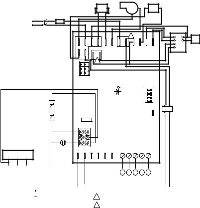
Fig. 1. Typical ST9120B,U wiring connections in ST9120 system with S8600 Intermittent Pilot Ignition Control.
69-2252EF—07 |
6 |
ST9120B,U UNIVERSAL ELECTRONIC FAN TIMERS
HUMIDIFIER |
INDUCER |
AIR CLEANER |
TO 115/230 VAC
POWER SUPPLY |
FUSE |
L1 (HOT) 


L2 (N)
|
|
|
|
|
|
|
|
|
|
|
|
|
FAN |
STARTING |
|
|
|
|
|
|
|
|
|
|
|
|
|
CAP |
|
|
|
|
|
|
|
|
|
1 |
|
|
|
|
|
|
|
|
|
|
|
|
|
|
|
|
|
|
HI |
|
|
|
|
NEUTRAL |
|
|
|
|
|
|
|
|
|
|
ML |
|
|
|
|
|
|
|
|
|
|
|
|
|
MH |
|
|
|
|
|
UNUSED |
HUM |
IND |
L1 |
|
CONT |
EAC |
COOL |
HEAT |
LO |
|
|
|
|
|
|
|
|
|||||||||
|
|
|
|
|
2 |
|
|
|
|
|
|
|
|
|
24 VOLT |
|
|
|
|
|
|
|
|
|
|
|
|
|
|
COMMON |
|
|
|
|
|
|
|
|
|
|
|
|
|
|
24 VOLT |
|
|
|
J3 |
|
|
|
|
|
|
|
|
|
|
HOT |
|
|
|
|
|
|
|
|
|
|
|
|
|
|
EFT |
|
|
|
|
|
STATUS |
|
|
|
DELAY |
|
|
||
OUTPUT |
|
|
|
|
|
|
|
|
|
|
|
|
||
24 VOLT |
|
|
|
|
|
|
|
|
|
|
|
|
|
|
THERMOSTAT |
|
|
|
|
|
|
|
|
|
|
|
|
|
|
OR PRESSURE |
|
|
|
|
|
|
|
|
|
|
|
|
|
|
SWITCH |
|
|
|
|
|
|
|
|
|
|
|
|
|
|
|
|
|
|
|
|
|
|
|
|
|
TWIN |
|
115/230 VAC |
|
|
|
|
|
|
|
|
|
|
|
|
|
TRANSFORMER |
||
|
|
FUSE |
|
|
|
|
|
|
|
|
|
24 VAC |
||
|
|
|
|
|
|
|
|
|
|
|
|
|||
ROLLOUT |
LIMIT |
|
|
|
|
|
|
|
|
|
|
|
|
|
SWITCH |
SWITCH |
J1 |
|
|
|
|
|
|
|
|
|
|
|
|
|
|
C |
X |
LIM PRSW Y |
C |
C |
G |
Y |
W |
R |
|
|
|
|
SV9500 |
|
|
|
|
|
|
|
|
|
|
|
|
|
|
HOT SURFACE |
|
|
|
|
|
|
|
|
|
|
|
|
|
|
 IGNITION CONTROL
C G Y W R
THERMOSTAT
PRESSURE SWITCH
1 CONNECT ONLY IF CONTINUOUS SPEED IS AVAILABLE AND USED.
DENOTES LINE VOLTAGE WIRING
DENOTES LOW VOLTAGE WIRING |
2 CONNECT ONLY IF CONTINUOUS SPEED IS NOT USED. |
M27705
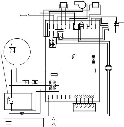
Fig. 2. Typical ST9120B,U wiring connections in ST9120 system with SV9500/SV9501 SmartValve™ Control.
7 |
69-2252EF—07 |

ST9120B,U UNIVERSAL ELECTRONIC FAN TIMERS |
|
|
|
|
|
|
|
|
|
|
||||
|
|
|
|
|
|
|
|
|
|
|
|
|
FAN |
STARTING |
|
|
MAIN |
|
|
|
|
|
|
|
|
|
|
CAP |
|
|
|
|
|
|
|
|
|
|
|
|
|
HI |
|
|
|
|
LIMIT |
|
NEUTRAL |
UNUSED |
HUM |
IND |
L1 |
|
CONT EAC COOL |
HEAT |
|
||
|
|
|
|
|
|
LO |
|
|||||||
|
|
ROLLOUT |
|
|
|
|
|
|
|
|
|
HL |
|
|
|
|
|
|
|
|
|
|
|
|
|
HH |
|
||
|
|
VENT |
|
|
|
|
|
|
|
|
|
|
|
|
|
|
AUX |
|
|
|
|
|
|
|
|
|
|
|
|
|
|
|
|
|
|
J3 |
|
|
|
|
|
|
|
|
TO 115/230 VAC |
|
|
|
|
|
|
STATUS |
|
DELAY |
|
|
|||
|
|
|
|
|
|
|
|
|
|
|
||||
|
|
|
|
|
|
|
|
|
|
|
|
|
||
POWER SUPPLY |
|
|
|
|
|
|
|
|
|
|
|
|
|
|
L2 (N) |
FUSE |
|
|
|
|
|
|
|
|
|
|
|
|
|
L1 (HOT) |
|
WIRE HARNESS ADAPTER |
|
|
|
|
|
|
TWIN |
115/230 VAC |
||||
|
|
1 |
L2 WHITE |
|
|
|
|
|
|
|
TRANSFORMER |
|||
|
|
|
|
|
|
|
|
|
|
|
||||
INDUCER |
|
2 |
L2 WHITE |
3 |
FUSE |
|
|
|
|
|
|
24 VAC |
||
|
3 |
PS/MV DRIVE ORANGE |
|
|
|
|
|
|
|
|
|
|
||
|
|
4 |
LIMIT RED |
6 |
J1 |
|
|
|
|
|
|
|
|
|
|
|
5 |
LIMIT RED |
1 |
|
|
|
|
|
|
|
|
|
|
|
GAS |
6 L1 BLACK |
4 NC |
|
|
|
|
|
|
|
|
|
|
|
|
VALVE |
7 |
24V GND YELLOW |
2 |
|
|
|
|
|
|
|
|
|
|
|
|
8 |
MV SENSE VIOLET |
5 |
|
|
|
|
|
|
|
|
|
|
|
|
9 |
INDUCER BLUE |
|
C |
X LIM PRSW Y |
C |
C G Y W R |
|
|
|
|||
|
|
|
|
|
|
|
|
|||||||
|
|
PRESSURE |
|
|
|
|
|
|
|
|
|
|
|
|
|
|
SWITCH |
|
|
|
|
|
|
|
|
|
|
|
|
|
|
DENOTES LINE VOLTAGE WIRING |
|
|
|
|
C |
G |
Y W R |
|
|
|
||
|
|
|
|
|
|
THERMOSTAT |
|
|
|
|||||
|
|
DENOTES LOW VOLTAGE WIRING |
|
|
|
|
|
|
|
|||||
|
|
|
|
|
|
|
|
|
|
|
M27777 |
|||
|
|
|
|
|
|
|
|
|
|
|
|
|
|
|
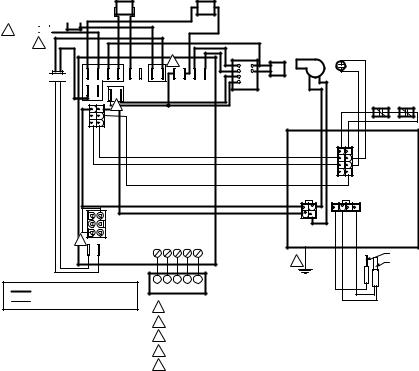
Fig. 3. Typical ST9120B,U wiring connections in ST9101 system.
|
|
|
|
|
|
|
|
|
INDUCER |
|
|
AIR |
|
|
||
|
|
|
|
|
|
|
HUMIDIFIER |
|
CLEANER |
|
|
|||||
|
|
|
|
|
|
|
|
|
|
|
|
|
||||
|
|
TO 115/230 VAC |
FUSE |
|
|
|
|
|
|
|
|
|
|
|
|
|
|
|
POWER SUPPLY |
|
|
|
|
|
|
|
|
|
|
|
|
||
|
|
|
L1 (HOT) |
|
|
|
|
|
|
|
|
|
|
|
|
|
24 VOLT |
|
L2 (N) |
|
|
|
|
|
|
|
|
|
|
|
|
|
|
|
|
|
|
|
|
|
|
|
|
|
|
|
|
STARTING |
||
COMMON |
|
|
|
|
|
|
|
|
|
|
|
|
|
FAN |
||
|
|
|
|
|
|
|
|
|
|
|
|
|
CAP |
|||
|
24VOLT |
|
|
|
|
|
|
|
|
|
|
|
|
|
||
|
|
|
|
|
|
|
|
|
|
1 |
|
|
|
|
||
|
|
|
|
|
|
|
|
|
|
|
|
|
HI |
|
||
|
HOT |
|
|
|
|
|
|
|
|
|
|
|
|
|
||
|
|
|
|
NEUTRAL |
|
|
|
|
|
|
|
|
|
|
||
|
EFT |
|
|
|
UNUSED |
HUM |
IND |
|
|
CONT |
EAC |
COOL |
HEAT |
ML |
|
|
SWITCH |
|
|
|
|
|
MH |
|
|||||||||
24 VOLT OUTPUT |
|
|
|
|
|
|
|
|
|
|
|
|
|
LO |
|
|
THERMOSTAT |
|
|
|
|
|
|
|
|
|
|
|
|
|
|
|
|
OR PRESSURE |
|
|
|
|
|
|
|
|
|
|
|
|
|
|
|
|
|
|
|
|
|
|
|
2 |
|
|
|
|
|
|
|
|
|
|
|
SV9500 |
|
|
|
|
|
|
|
|
|
|
|
|
|
|
|
|
HOT SURFACE |
|
|
|
|
|
|
|
|
|
|
|
|
|
|
|
|
IGNITION CONTROL |
|
J3 |
|
|
|
|
|
|
|
|
|
|
||
|
|
|
|
|
|
|
|
|
|
|
|
|
|
|
||
|
|
|
|
|
|
|
|
STATUS |
|
|
|
DELAY |
|
|
||
|
|
|
|
|
|
|
|
|
|
|
|
|
|
|
||
|
|
|
|
|
|
|
|
|
|
|
|
|
TWIN |
115/230 VAC |
||
N.O. |
N.C. |
|
|
|
|
|
|
|
|
|
|
|
TRANSFORMER |
|||
|
|
|
|
|
FUSE |
|
|
|
|
|
|
|
|
24 VAC |
|
|
|
|
|
|
|
|
|
|
|
|
|
|
|
|
|
||
PRESSURE |
COM |
ST9141 WIRE HARNESS ADAPTER |
|
|
|
|
|
|
|
|
|
|
|
|
||
SWITCH |
|
J1 |
|
|
|
|
|
|
|
|
|
|
|
|||
|
|
|
24V RED |
|
|
|
|
|
|
|
|
|
|
|
|
|
|
|
1 |
1 |
|
|
|
|
|
|
|
|
|
|
|
|
|
|
|
2 |
24V GNDYELLOW |
2 |
|
|
|
|
|
|
|
|
|
|
|
|
|
BURNER |
3 |
WORANGE |
3 |
|
|
|
|
|
|
|
|
|
|
|
|
|
4 |
24VRED |
4 |
|
|
|
|
|
|
|
|
|
|
|
|
|
|
LIMIT |
5 |
FTVIOLET |
5 |
|
|
|
|
|
|
|
|
|
|
|
|
|
|
BRN LIMGRAY |
|
|
|
|
|
|
|
|
|
|
|
|
||
|
|
6 |
PRSWBROWN |
6 |
C |
X LIM PRSW Y |
C |
C |
G |
Y |
W |
R |
|
|
|
|
|
|
7 |
PRIM LIMRED |
|
|
|
|
|
|
|
|
|
|
|
|
|
|
|
8 |
|
|
|
|
|
|
|
|
|
|
|
|
|
|
|
|
N.C. |
|
|
|
|
|
|
|
|
|
|
|
|
|
|
|
|
9 |
|
|
|
|
|
|
|
|
|
|
|
|
|
|
|
PRIMARY |
|
|
|
|
|
|
|
C |
G |
Y |
W |
R |
|
|
|
|
LIMIT |
|
|
|
|
|
|
|
|
THERMOSTAT |
|
|
|
|||
|
|
|
|
|
|
|
|
|
|
|
|
|
||||
|
|
DENOTES LINE VOLTAGE WIRING |
1 |
CONNECT ONLY IF CONTINUOUS SPEED IS AVAILABLE AND USED. |
|
|
|
|
|||
|
|
DENOTES LOW VOLTAGE WIRING |
2 |
CONNECT ONLY IF CONTINUOUS SPEED IS NOT USED. |
M27722 |
|
|
||||
|
|
|
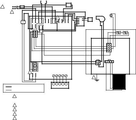
Fig. 4. Typical ST9120B,U wiring connections in ST9141 system with SV9500/SV9501 SmartValve™ Control.
69-2252EF—07 |
8 |
ST9120B,U UNIVERSAL ELECTRONIC FAN TIMERS
HUMIDIFIER
TO 115 VAC
POWER SUPPLY FUSE
L1 (HOT)


1 L2 (N) 


2
115 VAC TRANSFORMER 
 24 VAC

LOAD |
COMMON |
NEUTRAL |
UNUSED |
HUM |
IND |
|
|
5 |
|
|
J3 |
|
|
J1
3 |
C |
X |
|
|
DENOTES LINE VOLTAGE WIRING
DENOTES LOW VOLTAGE WIRING
|
AIR CLEANER |
|
|
|
|
|
|
|
|
|
|
STARTING |
PRESSURE |
|
|
|
4 |
|
FAN |
CAP |
INDUCER |
SWITCH |
|
|
|
HI |
|
|
|
|
|
|
|
|
ML |
|
|
|
|
L1 |
CONT EAC COOL |
HEAT |
MH |
|
|
|
|
LO |
|
|
|
|
|||
|
|
|
|
|
|
|
|
|
|
|
|
|
NEUTRAL |
HOT |
LIMIT ROLLOUT |
|
|
|
|
|
SWITCH SWITCH |
||
|
|
|
|
|
SV9501; |
|
|
|
|
|
|
|
SV9520 |
|
|
|
|
|
|
|
|
C1 |
|
|
|
|
|
C |
|
|
|
|
|
|
|
R |
|
|
|
|
|
|
|
DATA |
|
|
|
|
|
|
|
NEUTRAL |
C3 |
C2 |
|
|
|
|
|
|
|
|
|
|
|
|
|
L1 |
|
|
|
C G |
Y W R |
|
|
|
|
|
|
|
|
|
|
|
|
|
FLAME ROD |
|
|
|
|
|
2 |
|
HOT |
|
|
|
|
|
|
|
SURFACE |
C G Y W R |
|
|
|
|
|
IGNITER |
|
|
|
|
|
|
|
||
THERMOSTAT |
|
|
|
|
|
|
|
1THERE MUST BE 115 VAC CONNECTED TO L1 (HOT) ON ST9120U, ST9120B.
2APPLIANCE CHASSIS MUST HAVE RELIABLE CONNECTION TO EARTH GROUND.
3JUMPER PLUG MUST BE ATTACHED TO J1 CONNECTOR.
4CONNECT ONLY IF CONTINUOUS SPEED IS AVAILABLE AND USED.
5 CONNECT ONLY IF CONTINUOUS SPEED IS NOT USED |
M16880 |
Fig. 5. Typical ST9120B,U wiring connections in ST9160 system with SV9510/SV9520 SmartValve™ Control.
9 |
69-2252EF—07 |
ST9120B,U UNIVERSAL ELECTRONIC FAN TIMERS
|
HUMIDIFIER |
||
|
|
|
AIR |
TO 115/230 VAC |
|
|
CLEANER |
POWER SUPPLY FUSE
1 |
L1 (HOT) |
|
|
|
|
|
|
|
|
|
|
|
|
|
|
|
L2 (N) |
|
|
|
|
|
|
|
|
|
|
|
PRESSURE |
|
|
|
2 |
|
|
|
|
|
|
|
|
|
|
|
|
||
|
|
|
|
|
|
|
|
|
STARTING |
SWITCH |
|
||||
|
|
|
|
|
|
|
|
|
|
INDUCER |
|
|
|||
|
|
|
|
|
|
|
|
|
|
FAN |
CAP |
|
|
|
|
|
|
|
|
|
|
|
|
4 |
|
HI |
|
|
|
|
|
|
115/230 VAC |
|
NEUTRAL |
|
|
|
|
|
|
|
|
|
|
||
|
|
|
|
|
|
|
|
ML |
|
|
|
|
|
||
|
TRANSFORMER |
|
|
|
|
|
|
|
MH |
|
|
|
|
|
|
|
24 VAC |
|
|
HUM |
IND |
L1 |
CONT EAC COOL |
HEAT |
LO |
|
|
|
|
|
|
|
COMMON |
|
|
|
|
|
|
|
|||||||
|
LOAD |
|
|
|
|
HOT |
LIMIT |
ROLLOUT |
|||||||
|
5 |
|
|
NEUTRAL |
SWITCH SWITCH |
||||||||||
|
UNUSED |
|
|
SV9540; |
|
|
|||||||||
|
|
|
|
J3 |
|
|
|
|
|
|
|
SV9640 |
|
|
|
|
|
|
|
|
|
|
|
|
|
|
|
|
C1 |
|
|
|
|
|
|
|
|
|
|
|
|
C |
|
|
|
|
|
|
|
|
|
|
|
|
|
|
|
R |
|
|
|
|
|
|
|
|
|
|
|
|
|
|
|
24VAC |
|
|
|
|
|
|
|
|
|
|
|
|
|
|
|
DATA |
|
|
|
|
|
|
|
|
|
|
|
|
|
|
|
NEUTRAL |
C3 |
|
C2 |
|
|
|
|
|
|
|
|
|
|
|
|
|
|
|
|
||
|
|
|
|
|
|
|
|
|
|
L1 |
|
|
|
|
|
|
|
3 |
C |
J1 |
|
|
|
|
|
|
|
|
|
|
|
|
|
X |
|
|
C G |
Y W R |
|
|
|
|
|
|
|
||
|
|
|
|
|
|
|
|
|
|
|
|
|
|
||
|
|
|
|
|
|
|
|
|
|
|
|
2 |
|
|
Q345 |
|
|
|
|
|
|
|
|
|
|
|
|
|
|
|
IGNITER- |
|
|
|
|
|
|
|
C G Y W R |
|
|
|
|
|
|
SENSOR |
|
|
|
|
|
|
|
|
|
|
|
|
|
|
|
||
|
DENOTES LINE VOLTAGE WIRING |
|
|
THERMOSTAT |
|
|
|
|
|
|
|||||
|
DENOTES LOW VOLTAGE WIRING |
|
|
|
|
|
|
|
|
|
|
|
|||
1FOR 115 VAC / 50, 60 HZ INSTALLATIONS, THERE MUST BE 115 VAC CONNECTED TO L1 (HOT) ON ST9120U, ST9120B. FOR 230 VAC / 60 HZ INSTALLATIONS, THERE MUST BE 115 VAC BETWEEN L1 (HOT) AND APPLIANCE CHASSIS.
FOR 230 VAC / 50 HZ INSTALLATIONS, USE ONLY WITH SMART VALVE RATED FOR THE SAME LINE VOLTAGE PARAMETERS.
2APPLIANCE CHASSIS MUST HAVE RELIABLE CONNECTION TO EARTH GROUND.
3JUMPER PLUG MUST BE ATTACHED TO J1 CONNECTOR.
4CONNECT ONLY IF CONTINUOUS SPEED IS AVAILABLE AND USED.
5 CONNECT ONLY IF CONTINUOUS SPEED IS NOT USED |
M27724A |
Fig. 6. Typical ST9120B,U wiring connections in ST9160 system with SV9540/SV9640 SmartValve™ Control.
69-2252EF—07 |
10 |
Loading...