


Technical Handbook
Sieger Apex

MAN0604 Issue 04 Feb 04 |
Apex |
2110M8030 |
|
|
|
SAFETY
Ensure that you read and understand this handbook BEFORE installing/operating the equipment. Pay particular attention to the Safety Warnings.
WARNINGS
1.This gas detection equipment is certified for and intended for use in potentially hazardous areas. Install and use the equipment in accordance with current local and national regulations.
2.Refer to the control drawings included in this document when installing the certified components.
3.Operators should be fully aware of the action to be taken if the gas concentration exceeds alarm level.
4.Donotmodifyoraltertheconstructionofanyoftheunitsasessentialsafetyandcertificationrequirements may be invalidated.
5.The equipment is not suitable for use in oxygen enriched atmospheres (>21%V/V). Oxygen deficient atmospheres (<10% V/V) may suppress some sensor outputs.
6.The equipment is intended for use at atmospheric pressure only and should not be used in pressures exceeding 1.1 bar.
Transmitter Unit only
1.INPUT VOLTAGE MUST NOT EXCEED THE STATED MAXIMUM (32V DC) AS ESSENTIAL SAFETY REQUIREMENTS MAY BE INVALIDATED AND THE UNIT MAY BE PERMANENTLY DAMAGED.
2.Alarms should not be reset until it is confirmed that gas is not present.
3.Hazardous voltages may exist at alarm contacts. Ensure power is disconnected at source prior to servicing contacts.
4.Gas events occurring while accessing the Transmitter Unit menus will not be reported locally.
5.Overrange flammable gas readings may indicate an explosive concentration of gas.
Certified Sensor only
1.When installed to measure flammable gas it is essential that either the Transmitter unit or control network is configured to latch the overrange condition. If the Transmitter unit local relays are used this should be achieved by enabling the overrange latching function of the Transmitter unit. Depletion of oxygen as a consequence of displacement by flammable gas can result in the gas reading returning to zero.
2.Change gas cartridges using the procedure described in this handbook. Failure to correctly follow the procedure could result in the wrong cartridge being installed, and possibly non-detection of events. Alternatively, extraneous alarms could be triggered by chemicals detected but not of concern at a particular location.
3.Sensor cartridges may contain corrosive solutions. Dispose of in accordance with local and national regulations.
4.During usage, as some gases may be hazardous, outlets from accessories, etc., e.g. Flow Housing, should exhaust to a safe area.
2

MAN0604 Issue 04 Feb 04 |
Apex |
2110M8030 |
|
|
|
SAFETY
CAUTIONS
1.Only the combustible gas detection portion of this instrument has been assessed for performance by CSA.
2.Refer to local or national regulations relative to installation and use at the site.
3.Installation should consider not only optimum siting for gas detection related to potential leak points, gas characteristicsandventilationbutalsoplacementwherethepotentialformechanicaldamageisminimised or avoided.
4.Observe precautions for handling electrostatic discharge sensitive devices when accessing the interior of the Transmitter Unit.
5.Calibration procedures should only be performed by qualified personnel.
6.Ensure that when forcing signals on the Transmitter Unit’s output that the effects on the network and controller are understood.
7.Ensure that the Apex Transmitter Unit or Junction Box flamepath is not damaged during dismantling procedures. The flamepath is formed by the mating surfaces of the unit’s top and base.
8.Duringinstallation/maintenanceonlyusethesuppliedparts.Replacementwithalternativeswillinvalidate certification.
9.Exposure to fluorinated hydrocarbons or silicones will poison the sensor beads on catalytic sensor cartridges. If a sensor is known to have been poisoned then it must be re-calibrated. If not sure then flow gas over the sensor and if the reading is incorrect re-calibrate within the cartridge’s tolerance value.
10.Only cartridges with the following part numbers can be fitted to the Certified Sensor:
2110B30x0, 31x0, 32x0, 33x0, 34x0 series 2110B3700 - 2110B3999 range
Note: |
Certified to CSA C22.2 No. 152 only when fitted with specific cartridges. |
|
See specifications for details. |
|
Performance assessed to EN50054/57 when fitted with cartridges |
|
Part No: 2110B3701& 2110B3704. See specifications for detail. |
11.When compliance with the ATEX EN50054 performance standard is required the warning and inhibit current shall not be configured to a value between than 3.1mA and 4.9mA
12.Do not use the unit where the temperature is lower than -40oC (-40oF) or higher than +65oC (149oF).
13.Exposures to gas above the recommended range may result in ambiguous readings and may require subsequent re-calibration of the sensor.
14.Review cartridge data sheets for operating temperatures and humidities, which are determined on a cartridge by cartridge basis.
15.Dispose of in accordance with local disposal regulations. Materials used:
Transmitter Unit |
|
Main Body: |
Stainless Steel |
User Interface: |
Zinc Alloy. |
Certified Sensor |
|
Main Body: |
Stainless Steel |
Certified Junction Box |
|
Main body: |
Stainless steel. |
3

MAN0604 Issue 04 Feb 04 |
Apex |
2110M8030 |
|
|
|
HELP US TO HELP YOU
Everyefforthasbeenmadetoensuretheaccuracyinthecontentsofourdocuments,however,Zellweger Analytics Limited can assume no responsibility for any errors or omissions in our documents or their consequences. Zellweger Analytics Limited would greatly appreciate being informed of any errors or omissions that may be found in our documents. To this end we include the following form for you to photocopy, complete and return to us so that we may take the appropriate action.
To: |
Marketing Communications |
From: |
|
Zellweger Analytics Limited |
Address: |
|
Hatch Pond House |
|
|
|
|
|
4 Stinsford Road |
|
|
Nuffield Estate |
|
|
POOLE. Dorset |
|
|
BH17 0RZ |
|
|
United Kingdom |
|
Tel.: |
+44 (0) 1202 676161 |
Tel.: |
Fax.: |
+44 (0) 1202 678011 |
Fax.: |
E-mail: |
sales@zelana.co.uk |
E-mail: |
|
|
|
I suggest the following corrections/changes be made to: |
.................. |
Marked up copies attached (as appropriate): |
Yes / No |
Please inform me of the outcome of this change: |
Yes / No |
|
|
For Marketing Communications, Zellweger Analytics Limited: |
|
Actioned By: |
|
Date: |
|
Response: |
|
Date: |
|
4

MAN0604 Issue 04 Feb 04 |
Apex |
2110M8030 |
|
|
|
CONTENTS
SAFETY |
|
|
2 |
HELP US TO HELP YOU |
4 |
||
1. INTRODUCTION |
8 |
||
2. OVERVIEW |
|
10 |
|
2.1 |
Transmitter Unit |
10 |
|
2.2 |
Certified Sensor |
12 |
|
2.3 |
Accessories |
14 |
|
|
2.3.1 |
Certified Junction Box |
14 |
|
2.3.2 |
Collecting Cone |
16 |
|
2.3.3 |
Flow Housing |
17 |
|
2.3.4 |
Weather Housing |
18 |
|
2.3.5 |
Sunshade |
18 |
|
2.3.6 |
Oxygen Transducer Adaptor |
19 |
|
2.3.7 |
Filters |
19 |
3. INSTALLATION |
20 |
||
|
General Installation Guidelines |
21 |
|
3.1 Transmitter Unit and Certified Sensor |
22 |
||
|
3.1.1 Installing the Transmitter Unit |
22 |
|
|
3.1.2 Fitting the Certified Sensor |
25 |
|
|
3.1.3 Installing the Gas Sensing Cartridge |
27 |
|
|
3.1.4 |
Transmitter Unit Configuration |
29 |
3.2 Certified Junction Box and Certified Sensor |
31 |
||
|
3.2.1 Installing the Certified Junction Box |
32 |
|
|
3.2.2 Fitting the Certified Sensor |
34 |
|
|
3.2.3 Installing the Gas Sensing Cartridge |
36 |
|
|
3.2.4 Certified Junction Box Configuration |
37 |
|
3.3 |
LonWorks Communications Board |
38 |
|
|
3.3.1 Removing the Transmitter Unit top |
39 |
|
|
3.3.2 Removing the Main PCB assembly from the top |
40 |
|
|
3.3.3 Fitting the LonWorks Communication Board to |
|
|
|
|
the Main PCB |
40 |
|
3.3.4 Refitting the Main PCB Assembly into the Top |
41 |
|
|
3.3.5 Connecting the LonWorks Network Wiring |
42 |
|
|
3.3.6 Refitting the Transmitter Unit Top |
43 |
|
3.4 |
Accessories |
46 |
|
|
3.4.1 Flow Housing, Weather Protection, Collecting Cone |
46 |
|
|
3.4.2 |
Sunshade |
47 |
5

MAN0604 Issue 04 Feb 04 |
Apex |
2110M8030 |
|
|
|
CONTENTS
4. OPERATION |
|
49 |
|
4.1 |
Display and Control Buttons |
49 |
|
|
4.1.1 |
LCD screen |
50 |
|
4.1.2 |
Control buttons |
50 |
4.2 |
Start-up |
51 |
|
4.3 |
Passwords |
52 |
|
|
4.3.1 |
Setting/changing passwords |
53 |
|
4.3.2 |
Password reset |
55 |
4.4 |
Menus |
|
56 |
|
4.4.1 |
Calibration Menu |
57 |
|
4.4.2 |
Configuration Menu |
63 |
|
4.4.3 |
Display Menu |
71 |
|
4.4.4 |
History Log Menu |
74 |
|
4.4.5 |
Change Passwords Menu |
75 |
|
4.4.6 |
Reset Passwords |
76 |
4.5 |
User Tasks |
77 |
|
4.6 |
Fault Diagnosis |
78 |
|
|
4.6.1 |
Displayed Error Messages |
78 |
|
4.6.2 |
General Faults |
79 |
|
4.6.3 |
4-20mA output signal ranges and fault conditions |
80 |
|
4.6.4 |
Clearing latched alarms |
81 |
4.7 |
System Calibration |
82 |
|
4.8 |
Binding Communication Boards to Networks |
87 |
|
5. MAINTENANCE |
89 |
||
5.1 |
Routine maintenance schedule |
89 |
|
5.2 |
Maintenance Procedures /Parts Replacement |
90 |
|
|
5.2.1 |
Changing the Certified Sensor Filter |
90 |
|
5.2.2 |
Changing the Certified Sensor Cartridge |
91 |
|
5.2.3 |
Changing the Certified Sensor |
95 |
|
5.2.4 |
Changing the Transmitter Unit Front Panel Assembly |
98 |
APPENDIX A - SPECIFICATIONS |
100 |
||
A.1 Transmitter Unit and Sensor |
100 |
||
|
A.1.1 |
Gases and Ranges |
100 |
|
A.1.2 |
Input/Output |
100 |
|
A.1.3 |
Monitoring functions |
102 |
|
A.1.4 |
Performance |
102 |
6

MAN0604 Issue 04 Feb 04 |
Apex |
2110M8030 |
|
|
|
CONTENTS
|
A.1.5 |
Environmental |
102 |
|
A.1.6 |
Storage (excluding cartridge) |
102 |
|
A.1.7 |
EMC |
103 |
|
A.1.8 |
Enclosure |
103 |
|
A.1.9 |
Configuration |
103 |
|
A.1.10 |
Certification and Approvals |
103 |
|
A.1.11 |
Calibration intervals |
105 |
A.2 |
Cartridges |
105 |
|
|
A.2.1 |
Cartridge tables |
105 |
A.3 |
Accessories |
111 |
|
|
A.3.1 |
Certified Junction Box |
111 |
|
A.3.2 |
Sunshade |
112 |
|
A.3.3 |
Flow Housing |
113 |
|
A.3.4 |
Weather Protection |
113 |
|
A.3.5 |
Collecting Cone |
113 |
|
A.3.6 |
Oxygen Transducer Adaptor |
113 |
A.4 LonWorks Communications Board |
113 |
||
|
A.4.1 |
LonWorks Network Variables |
114 |
|
A.4.2 |
Node Object |
114 |
|
A.4.3 |
Sensor Object |
116 |
|
A.4.4 |
Virtual Function Block |
117 |
|
A.4.5 |
Implementation of nviRequest |
118 |
|
A.4.6 |
Interpretation of nvoStatus |
119 |
APPENDIX B - CERTIFICATION |
120 |
||
B.1 |
Transmitter Unit |
120 |
|
B.2 |
Certified Sensor |
121 |
|
B.3 |
Certified Junction Box |
123 |
|
B.4 |
Accessories |
124 |
|
B.5 |
Control Drawings |
125 |
|
APPENDIX C - ACCESSORIES & SPARE PARTS |
127 |
||
C.1 |
Accessories |
127 |
|
C.2 |
Digital Communications Board |
127 |
|
C.3 |
Spares |
127 |
|
APPENDIX D - GLOSSARY |
128 |
||
7

MAN0604 Issue 04 Feb 04 |
Apex |
2110M8030 |
|
|
|
1. INTRODUCTION
Apex is a gas detection system that consists of a Transmitter Unit, a certified gas sensor and a set of accessories. The Transmitter Unit, Certified Sensor and Certified Junction Box accessory are all certified for use in potentially hazardous areas and are protected against water and dust ingress to IP67.
Typical working environments are oil and gas distribution, petroleum extraction and chemical manufacture.
System installation is straightforward. Components should be installed in accordance with the procedures described in this handbook and to local or national installation codes of practice.
The Transmitter Unit acts as the local system controller and features a large LCD screen and four control buttons that are used for operator interaction. Control of the system is implemented via a system of softwaredriven hierarchical menus that include such operations as cartridge change, system configuration, etc. Remote control of the system can be made via an optional digital interface.
The Transmitter Unit can have the Certified Sensor fitted to it locally or mounted remotely using a Certified Junction Box and additional cabling up to 100 metres long.
The Transmitter Unit provides a 4-20mA output, as well as an optional digital output. Relays for operating locally-wired devices, such as lights, horns, etc. are included. The range of accessories enhances operation of the system and includes a collecting cone, weather protection, etc.
The Certified Sensor is compatible with a range of more than 40 sensor cartridges that use catalytic bead, thick film and electrochemical cells.
The interchangeable sensor cartridge determines which gas is monitored. All gas cartridges are fully calibrated when supplied.
The Certified Sensor uses intrinsically safe circuits to drive the cartridges. Cartridges may therefore be exchanged without powering down even in the presence of an explosive gas atmosphere.
Field calibration of the sensor, if required, is also possible. The cartridges available are listed in Appendix A.
The output from the sensor provides a gas concentration reading that is displayed on the LCD screen on the front of the Transmitter Unit and is also transmitted on the 4-20mA output and the optional digital interface.
8

MAN0604 Issue 04 Feb 04 |
Apex |
2110M8030 |
|
|
|
1. INTRODUCTION
This handbook consists of the following parts:
• |
Chapter 1 |
Introduction |
• |
Chapter 2 |
Overview |
• |
Chapter 3 |
Installation |
• |
Chapter 4 |
Operation |
• |
Chapter 5 |
Maintenance |
• |
Appendix A |
Specifications |
• |
Appendix B |
Certification |
•Appendix C Accessories & Spare Parts
• |
Appendix D Glossary |
Information notices
The types of information notices used throughout this handbook are as follows:
|
WARNING |
! |
Indicates hazardous or unsafe practice which could result |
in severe injury or death to personnel. |
Caution: Indicates hazardous or unsafe practice which could result in minor injury to personnel, or product or property damage.
Note: Provides useful/helpful/additional information.
Trademarks
The following trademarks are used in this handbook:
Teflon® and Freon® are registered trademarks of E.I. DuPont de Nemours and Co.
LonWorks®, Echelon®, Neuron®, and LonTalk® are registered trademarks of Echelon Corporation.
If more information outside the scope of this technical handbook is required please contact Zellweger Analytics.
9
MAN0604 Issue 04 Feb 04 |
Apex |
2110M8030 |
|
|
|
2. OVERVIEW
This chapter provides an overview of the following system components, and provides their dimensions:
•Transmitter Unit
•Certified Sensor
•Accessories
For installation information see Chapter 3.
Also see drawing 2110C8049 Outline Dimensions of Certified Transmitter, Sensor & Accessories (available on request from Zellweger Analytics).
2.1TRANSMITTER UNIT
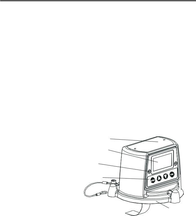
The Transmitter Unit provides a mounting point for a Certified Sensor and contains all the electronics associated with the gas detection system.
It features an LCD display screen that displays the controlling software menu system, and also a set of buttons that let an operator/user interact with the system by accessing the menus and responding to displayed messages.
The Transmitter Unit is shown with a Certified Sensor fitted.
Certification label
LCD screen
LCD screen assembly securing screw
(2 off)
Buttons
Top retaining cable
Ribbon cable |
Unit top |
10
MAN0604 Issue 04 Feb 04 |
Apex |
2110M8030 |
|
|
|
2. OVERVIEW
Interconnect PCB
Locating pins
Captive bolt
(3 off)
External earth
Certified
Sensor mounting
Unit base
Cable/conduit entry (2 off)
 Cable/conduit entry sealing plug (1 off)
11
MAN0604 Issue 04 Feb 04 |
Apex |
2110M8030 |
|
|
|
2. OVERVIEW
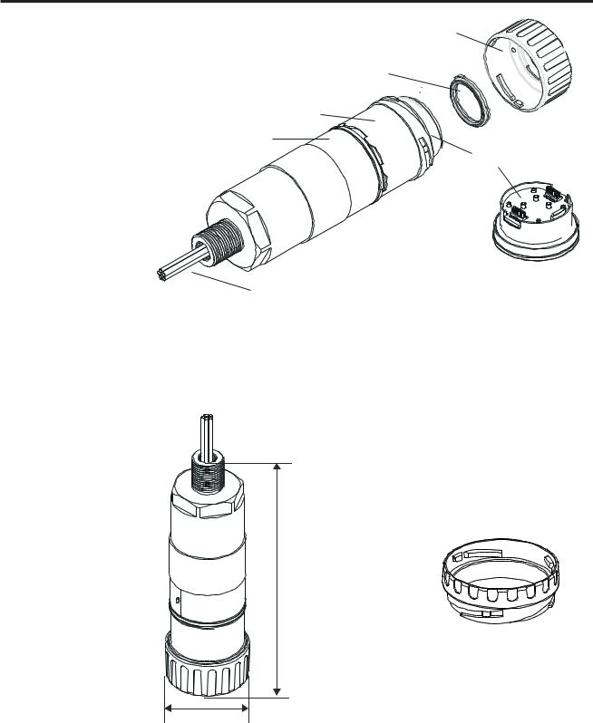
2.2CERTIFIED SENSOR
The Certified Sensor consists of the sensor body and one of four types of replaceable gas cartridge and the electronics to output gas sensing data to the Apex Transmitter Unit. The Certified Sensor can be fitted with any one of a number of accessories, the majority of which fit in place of the sensor cap (see 2.3).
The four types of cartridge are:
•electrochemical cell
•catalytic (SG16 type)
•oxygen
•thick film
Caution: Only cartridges with the following part numbers can be fitted to the Certified Sensor:
2110B30x0, 31x0, 32x0, 33x0, 34x0 series
2110B3700 - 2110B3999 range
Certified Sensor approved to CSA C22.2 No. 152 only when fitted with specific cartridges installed. See specifications for details.
The sensor should be mounted in the vertical orientation with the cartridge facing downwards.
12
MAN0604 Issue 04 Feb 04 |
Apex |
2110M8030 |
|
|
|
2. OVERVIEW
Cap or accessory
Seal or optional filter
Sensor body
Certification label
Cartridge
Sensor cable
All the gas cartridges are the same size except for the Oxygen cartridge, which is larger than the rest. To allow for its extra length an Oxygen Transducer Adaptor, supplied with the cartridge, mounts on the sensor bayonet fixing. The Oxygen cartridge is then inserted and the cap or accessory fitted.
Z
E
L
L
W
E
G
E
R
165mm (177mm with Oxygen transducer)
Oxygen transducer adaptor
53mm
13

MAN0604 Issue 04 Feb 04 |
Apex |
2110M8030 |
|
|
|
2.OVERVIEW
2.3ACCESSORIES
The Apex accessories provide optional equipment that can, for example, protect the Certified Sensor in harsh external environments and assist gas monitoring. All of the sensor accessories are easily fitted.
The following accessories are available:
•Certified Junction Box (Part Numbers: ATEX EEXd 2110B2100, UL/CSA [Explosion proof] 2110B2103) - two types for remote mounting a Certified Sensor.
•Collecting Cone (Part No: 2110B2151) - for use when monitoring lighter-than-air gases.
•Flow Housing (Part No: 21110B2140) - to aid sensor calibration and gas sample monitoring.
•Weather Housing (Part No: 2110B2150) - to protect the sensor from harsh weather.
•Sunshade (Part No: 2110B2152) - to protect the sensor from direct sunlight.
•Filters - three different filters to provide protection for the gas sensing cartridge.
•O2 Transducer Adaptor - supplied with Oxygen cartridges to allow for their longer length over standard cartridges.
2.3.1Certified Junction Box
Part Numbers: |
|
ATEX EEXd |
2110B2100 |
UL/CSA (Explosion proof) |
2110B2103 |
The Certified Junction Box accessory is used to mount a Certified Sensor remotely from the Transmitter Unit, and provides a connection point for the sensor and field wiring.
14

MAN0604 Issue 04 Feb 04 |
Apex |
2110M8030 |
|
|
|
2. OVERVIEW
Certification label
Lid retaining cable
Certified Junction
Box Top
Flamepath 

Terminal block |
Interconnect PCB |
|
(3 off) |
||
|
External
earth
 Flamepath
Cable / conduit |
Captive bolt |
|
(3 off) |
||
entry (2 off) |
||
|
Sensor mounting point
Cable entry sealing plug (1 off)
95mm


152mm
15
MAN0604 Issue 04 Feb 04 |
Apex |
2110M8030 |
|
|
|
2.OVERVIEW
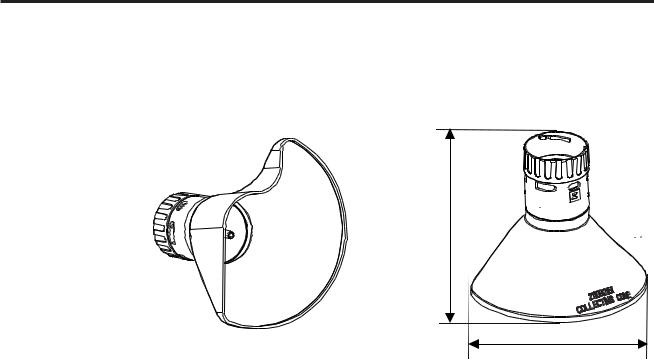
2.3.2Collecting Cone
Caution: This accessory should not be used for calibration purposes.
Part Number: |
2110B2151 |
127mm
160mm
The Collecting Cone is only for use when monitoring lighter-than-air gases.
Its shape is designed to:
•increase the collection area for lighter than air gases
•allow the gases to escape so that the time to clear an alarm is not excessively prolonged.
•fit against a wall or other flat surface
Conforms to CSA C22.2 No. 152 when fitted to the Certified Sensor with specific cartridges installed. See specifications for details.
The performance of this accessory has not been evaluated to EN50054/57
The Collecting Cone is attached to the sensor by means of a bayonet fitting.
Inside the cone is a 1/4in. O/D nozzle that can accept a tube and which provides a means to directly inject gas to the front of the sensor for gas response checking. The recommended flow rate for response checks is 1 litre per minute.
Accuracy of reading is not guaranteed.
Note: Do not carry out response checks at wind speeds greater than 10m/s (22mph).
16
MAN0604 Issue 04 Feb 04 |
Apex |
2110M8030 |
|
|
|
2.OVERVIEW
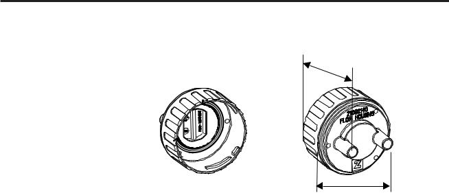
2.3.3Flow Housing
Part Number: |
2110B2140 |
43mm
53mm
The Flow Housing accessory provides a means of applying gas to the sensor for calibration and test (for details see section 4.7). It can also be used in sampling systems where a sample of gas is drawn through a tube to the sensor. Conforms to CSA C22.2 No. 152 when fitted to the Certified Sensor with specific cartridges installed. See specifications for details.
It provides:
•Two ports 8mm I/D to take 6mm tubing.
•A seal to stop gas dilution.
The housing works irrespective of which pipe the gas is applied to and flows gas across the face of the sensor rather than onto its face.
The difference in reading between a calibration made with the Flow Housing accessory and one made under diffusion conditions (in a tank of still gas) is less than 30%. The Flow Housing is suitable for flow rates in the range of 0.7 - 1 litre per minute flow across the cell.
A hydrophobic filter is supplied with the housing which must be used when calibrating sensors fitted with flammable gas cartridges.
When calibrating sensors fitted with other types of cartridge then the filter mounted in the sensor cap for normal gas sensing operation (if fitted) must be removed and used in the Flow Housing.
The Flow Housing accessory is attached to the sensor by means of a
17
MAN0604 Issue 04 Feb 04 |
Apex |
2110M8030 |
|
|
|
2. OVERVIEW
bayonet fitting.
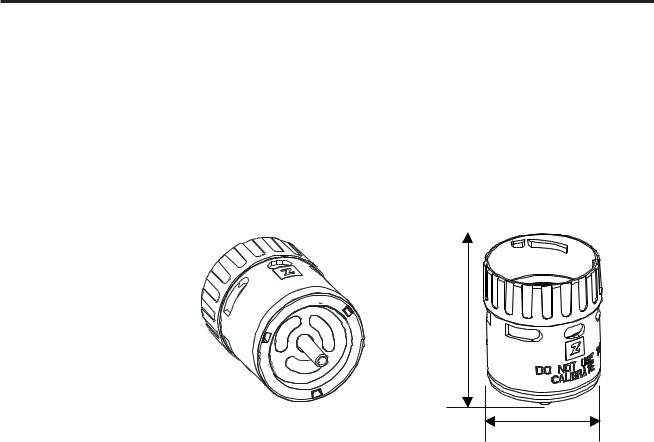
2.3.4 Weather Housing
Caution: This accessory should not be used for calibration purposes.
This accessory is not recommended for use in still air conditions.
Part Number: |
2110B2150 |
|
|
|
|
75mm
53mm
The Weather Housing accessory protects the sensor from hosing down/ cleaning operations and from extreme weather conditions, (e.g. torrential rain, storms, gales etc.). Conforms to CSA C22.2 No. 152 when fitted to the Certified Sensor with specific cartridges installed. See specifications for details.
The weather housing should not be fitted if the operating environment of the sensor does not require the additional protection afforded. In still air conditions the gas is transported to the face of the sinter is by diffusion only. Under such conditions the weather protection will slow the rate at which gas can reach the sensing element and consequently the speed of response of the sensor to gas will be reduced.
As well as providing weather protection the housing also provides a means to directly inject gas to the front of the sensor via a 1/4in. O/D nozzle for gas response checking. The recommended flow rate for response checks is 1 litre per minute. Accuracy of reading is not guaranteed. Do not carry out response checks at wind speeds greater than 10m/s (22mph).
The accessory is attached to the sensor by means of a bayonet fitting.
Note: The sensor will exhibit an increased reading(or indication) to gas with higher wind speeds. Fitting the weather housing with the supplied hydrophobic filter will eliminate this effect but increase the response time.
18
MAN0604 Issue 04 Feb 04 |
Apex |
2110M8030 |
|
|
|
2.OVERVIEW
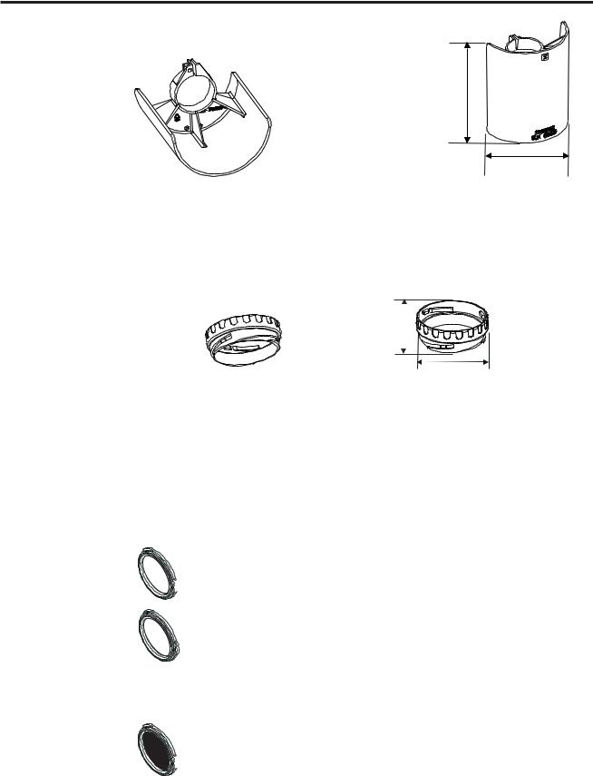
2.3.5Sunshade
Part Number: |
2110B2152 |
145mm
115mm
The Sunshade prevents excessive heating of the sensor by direct sunlight. Conforms to CSA C22.2 No. 152 when fitted to the Certified Sensor with specific cartridges installed. See specifications for details.
The performance of this accessory has not been evaluated to EN50054/57. The sunshade is fitted to the sensor body by means of a clamp.
2.3.6 Oxygen Transducer Adaptor
18mm
53mm
The Oxygen Transducer Adaptor is supplied with the Oxygen cartridge and is necessary because the depth of the Oxygen cartridge is more than that of the other gas cartridges.
The adaptor is attached to the Certified Sensor by means of a bayonet fitting. The Oxygen cartridge is fitted first and the sensor cap or accessory is then fitted to the adaptor by means of a bayonet fitting.
2.3.7 Filters
One of three different types of filter accessory can be fitted to the Certified Sensor in place of the rubber seal inside the sensor cap or accessory.
The three different types of filter available are:
Mesh filter - Part Number: 2110B2170 - for use in harsh environments. The filter prevents dirt from blocking the
 cartridge sinter.
Hydrophobic filter - Part Number: 2110B2171 - for use in environments where the cartridge front is likely to become wet. The hydrophobic material allows gas to pass through but not water. A hydrophobic filter is supplied with the Flow Housing and must be used when calibrating sensors fitted
with flammable gas cartridges.
Caution: The sensitivity of some cartridges may be degraded by the hydrophobic filter.
Carbon filter - Part Number: 2110B2172 - for use in environments where significant volatile compounds are present. The filter prevents the cartridge from being critically
 affected.
The performance of this accessory has not been evaluated to EN500054/57
19

MAN0604 Issue 04 Feb 04 |
Apex |
2110M8030 |
|
|
|
3. INSTALLATION
TheApexsystemcomponentscanbeusedtogetherinavarietyofwaysfordifferent installationrequirementsinahazardousenvironment.Forinstallationsofcertified componentsalsorefertotheControlDrawingsinAppendixB.
The following types of system installation are typical examples of those that can be made:
•ApexTransmitterunitwithaCertifiedSensorlocallymounted at the Transmitter Unit and field wiring from the Transmitter Unit to the system controller.
•Transmitter unit with a Certified Sensor mounted remotely in a Certified Junction Box, with field wiring between the two components, and from the Transmitter Unit to the system controller.
This chapter describes how to:
•carry out the installation of a Transmitter Unit and Certified Sensor
•install an Certified Junction Box accessory with Certified Sensor, suitable for remote operation
•install a LonWorks Communications Board in a Transmitter Unit
This is to enable the unit to be controlled and communicate over a digital network, e.g. LonWorks.
Caution: DonotinstallacommunicationsboardintoaULorCSAcertified
TransmitterUnitasapprovalforfitmentispending.
•install the system accessories
When fitting the system components consideration should be made regarding potential gas leak sources, density of the gas to be detected, probability of mechanical impacts and interference from other equipment and apparatus.
For optimum performance the Transmitter Unit and Certified Sensor should be installed in a location free from dust and direct sunlight. Sunshade and weather protection accessories for the sensor are available when operating in harsh external environments (see 3.4).
Refer to the relevant control system manual for external network connection information (e.g. field wiring, etc.).
20
MAN0604 Issue 04 Feb 04 |
Apex |
2110M8030 |
|
|
|
3. INSTALLATION
Also see drawing 2110C8049 Outline Dimensions of Certified Transmitter, Sensor & Accessories (available on request from Zellweger Analytics).
General Installation Guidelines
The following general points should be noted before any installation is carried out.
•Read all the instructions before starting any of the installation procedures.
•Identify a suitable location with a flat surface where the Apex Transmitter Unit/Certified Junction Box can be mounted.
•Identify external cable requirements and the necessary cable/conduit entry ports to be used on the Apex Transmitter Unit/Certified Junction Box.
•The Certified Sensor must always point downwards to avoid collection of fluids and other materials on the face.
•When fitting components that are certified also refer to the Control Drawings (see Appendix B).
The system components comply with the EMC requirements of EN50270. In ordertomaintaincompliancewiththisstandarditisessentialthatthecomponents are installed correctly as detailed below. It is the responsibility of the installation design authority to ensure that the electrical installation meets appropriate standards.
1.The unit should not be electrically connected to electrically noisy (dirty) metalwork or conductors. The case should be connected to a low noise (clean)earthlineviathescreenonthefieldcabling.
2.The entire length of the field cabling connected to each unit should be fully screenedwiththescreenconnectedtoalownoiseearth.
3.Thelownoiseearthlineshouldonlybeconnectedtosafetyearthatasingle point. Star earthing arrangements minimise earth current crosstalk. Field cablingshieldsshouldnotbeconnectedsuchthatearthloopsareproduced.
4.Theearthbondingarrangementmustensurethatthemaximumpeakvoltage betweentheunitcaseearthandanyfieldcableconductorislessthan350V. Voltages in excess of this can cause permanent damage to the unit's RFI protectionfilters.
5.Theuseofasingle,screeningcableforeachgasdetectorensuresmaximum screeningandminimumcrosstalk.Cablingarrangementswhichuseasingle cable for connecting field devices compromise screening, increase the
21
MAN0604 Issue 04 Feb 04 |
Apex |
2110M8030 |
|
|
|
3. INSTALLATION
potential for crosstalk and prevent implementation of true star earthing.
6.Any electrical interference induced onto the 4-20mA loop conductors by the installation must be kept below the levels necessary to comply with the general requirements of EN50270. In practice, this means that peak noise currents induced on the current loop should be no greater than ± 0.25mA.
7.The 0V rail of the control card/system is often directly connected to one side of the 4-20mAcurrent sensing resistor. Electrical noise on such a rail is therefore directly connected to the 4-20mA input. In order to avoid additional noise being induced on the 0V rail, it should not be common withthesafetyearth/groundwhichfrequentlycarriesahighlevelofelectrical noise.
8.The 24V supply should be free from large transients and fluctuations.
The type of cable used for field wiring between the Apex transmitter and control equipment, and between the Apex transmitter and Apex sensor if mounted remotely, should be selected to meet the environmental and hazardous area requirements. The cable internal construction should be a of the screened, multi- core,multi-strandedtype. Theterminalswithintheproductwillacceptamaximum conductorsizeof2.5mm2 (14AWG). Therecommendedminimumconductorsize is0.75mm2 (20AWG). Theconductorsshouldbesizedtogiveatotalpowersupply loop resistance of less than 30 Ohms (ECC cartridge) or 16 0hms (Catalytic cartridge). If remote mounting the sensor from the transmitter a 4-core, screened cable with a minimum conductor size of 0.75mm2 (20AWG) is required.
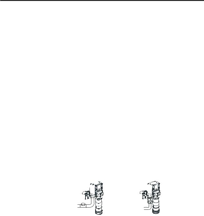
3.1TRANSMITTER UNIT AND CERTIFIED SENSOR
ThisinstallationconsistsofaTransmitterUnitwithCertifiedSensorlocallymounted at the Transmitter Unit together with field wiring.
Apex Transmitter Unit |
Apex Transmitter Unit |
with Certified Sensor |
with Certified Sensor |
(North America-style |
(European-style |
installation) |
installation) |
The system components can be installed by a single technician.
This procedure describes how to:
•install a Transmitter Unit
•fit a Certified Sensor to the local Transmitter Unit
•connect up the Certified Sensor and field wiring
•configure the Transmitter Unit relay and alarm settings
•install a gas sensing cartridge into the Certified Sensor
22
MAN0604 Issue 04 Feb 04 |
Apex |
2110M8030 |
|
|
|
3. INSTALLATION
Refer to the General Installation Guidelines at the beginning of this chapter.
3.1.1 Installing the Transmitter Unit
Cautions:
1. Observe precautions for handling electrostatic 
 discharge sensitive devices.
2.Ensure that the Apex Transmitter Unit flamepath is not damaged during this procedure. The flamepath is formed by the mating surfaces of the Apex Transmitter Unit top and base (see diagram).
(1)Isolate all associated power supplies and ensure that they remain OFF during the installation procedure. Ensure a gas free atmosphere.
(2)Attach the Apex Transmitter Unit to the supporting structure.
Drill two mounting holes (68mm apart) and use the unit’s mounting slots in the base with either two M10 bolts or a single 10mm U-bolt.
Unit top |
|
|
|
Top retaining |
|
|
|
cable |
|
|
|
Flamepath |
|
|
Ribbon cable |
|
|
|
|
Locating |
|
|
Interconnect |
pins |
|
|
|
|
|
PCB |
|
Cable securing |
|
|
|
|
|
|
|
screw |
|
|
Flamepath |
External |
|
|
Captive bolt |
earth |
|
|
(3 off) |
|
|
|
Certified |
Unit base |
Cable / conduit |
ZIF |
Sensor mounting |
|
entry (2 off) |
|
point |
 Cable/conduit entry sealing plug
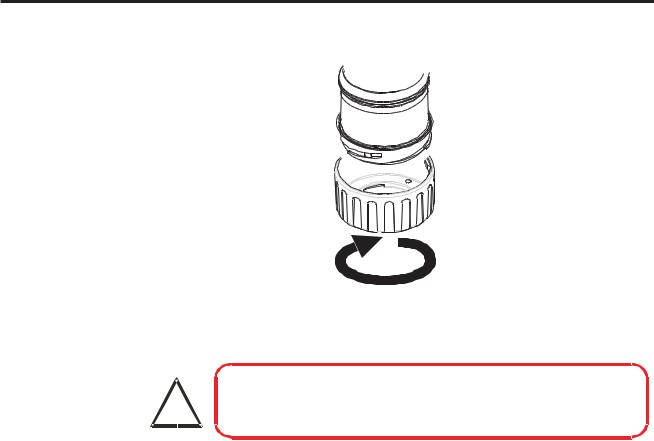
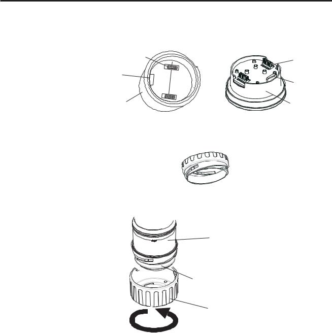
(3)Detach the top of the Transmitter Unit.
Unscrew the three captive M8 bolts in the base. Support the top and let the metal retaining cable, attaching the top to the base, hold the top. Take care not to damage or strain the ribbon cable between the top and the base.
(4)Fit and connect the field wiring.
See the subsequent wiring table and diagram. Use either:
23

MAN0604 Issue 04 Feb 04 |
Apex |
2110M8030 |
|
|
|
3. INSTALLATION
Conduit - using one or both of the 3/4 NPT conduit entries. Ensure that a conduit sealing fitting is installed within 460mm of the enclosure on all conduit runs.
Cable - using any suitable flameproof cable entry device certified as
Equipment to Directive 94/9/EC (ATEX).
Note: All unused cable/conduit entries must be sealed with a suitable certified sealing plug (one plug is supplied).
Typical wiring arrangements to the Transmitter Unit are (with all cables screened):
Single cable/conduit entry
Power |
4-20mA |
Digital Comms |
Relays |
Cores used |
|
|
|
|
|
2 |
1 |
- |
- |
3 |
|
|
|
|
|
2 |
2 |
- |
- |
4 |
|
|
|
|
|
2 |
2 |
- |
6 |
10 |
|
|
|
|
|
2 |
2 |
2 |
- |
6 |
|
|
|
|
|
2 |
- |
2 |
- |
4 |
Twin cable/conduit entries
Power |
4-20mA |
Digital Comms |
|
Relays |
|
|
|
|
|
2 |
2 (4 cores) |
- |
6 (6 cores) |
|
|
|
|
|
|
2 |
2 |
2 (6 cores) |
6 (6 cores) |
|
|
|
|
|
|
2 x power in |
- |
2 x comms in (4 cores) |
|
- |
2 x power out |
- |
2 x comms out (4 cores) |
- |
|
|
|
|
|
|
MorecomplexwiringschemesmayneedtouseexternalCertifiedJunction Boxes either because of cable/conduit entry capacity or because there are more than two cable/conduit destinations.
3.1.2 Fitting the Certified Sensor
(1)Fit the Certified Sensor to the Transmitter Unit.
24
MAN0604 Issue 04 Feb 04 |
Apex |
2110M8030 |
|
|
|
3. INSTALLATION
Transmitter Unit
base
Certified Sensor
mounting point
Certified Sensor
Feed the sensor cable through the Certified Sensor mounting point at the frontoftheTransmitterUnitbase.Screwthesensorfirmlyintothemounting point until it is fully home.
(2)Connectthesensorwiring.
See the following wiring table and diagram.
Terminal |
|
Function |
Colour |
Recommended |
|
Number |
|
|
|
Wire Length |
|
SK3 |
|
1 |
CAN_L |
White |
40mm |
(Sensor) |
|
2 |
CAN_H |
Green |
40mm |
|
|
3 |
+V |
Red |
40mm |
|
|
4 |
0V |
Black |
40mm |
|
|
5 |
Screen |
|
40mm |
SK4 |
|
1 |
NET1 |
|
60mm |
(Comms |
|
2 |
NET2 |
|
60mm |
and |
|
|
|
|
|
|
3 |
Ground |
|
50mm |
|
Power) |
|
||||
|
|
4 |
4 - 20mA - |
|
50mm |
|
|
5 |
4 - 20mA + |
|
50mm |
|
|
6 |
0V |
|
50mm |
|
|
7 |
+24Vdc (18-32Vdc) |
50mm |
|
SK6 |
|
1 |
Fault |
|
50mm |
(Relays) |
|
2 |
Fault common |
|
50mm |
|
|
3 |
Alarm 1 |
|
50mm |
|
|
4 |
Alarm 1 common |
|
50mm |
|
|
5 |
Alarm 2 |
|
50mm |
|
|
6 |
Alarm 2 common |
|
50mm |
G |
- |
Earth |
Green/Yellow |
|
|
25
MAN0604 Issue 04 Feb 04 |
Apex |
2110M8030 |
|
|
|
3. INSTALLATION
Ground
SK4
SK6
Ground
SK3
(3)Configure the Transmitter Unit if required.
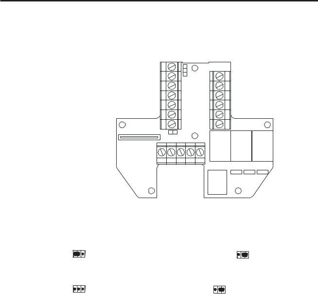
SetthelinksontheInterconnectPCBfortherequiredrelaycontactsettings and for the 4-20mA topology. See 3.1.4.
(4)Refit the top to the base.
Cautions:
1.Ensurethatthereisnomoistureinsidetheunitbeforefittingthetop.
2.Use only the captive bolts supplied, replacement with alternative bolts will invalidate certification.
Follow the reverse of the removal procedure supporting the top. The top should be positioned using the locating pins on the Apex Transmitter Unit base and then lowered onto the base.
Ensure that the lid retaining cable and wiring is not trapped and the O-ring in the top is correctly located.
Ensure that the ribbon cable is not twisted and is correctly positioned. Check that there is no discernible gap between the top and the base. Tighten the three captive M8 bolts to 5Nm (3.68 foot-pounds).
26
MAN0604 Issue 04 Feb 04 |
Apex |
2110M8030 |
|
|
|
3.INSTALLATION
3.1.3Installing the Gas Sensing Cartridge
(1)Remove the cap from the Certified Sensor body.
 Sensor
body
 Sensor
cap
Rotatethecaporaccessory1/4turninananticlockwisedirectiontorelease the bayonet fitting.
(2)Fit the gas sensing cartridge into the sensor body.
|
WARNING |
! |
Sensor Cartridges may contain corrosive solutions. |
Dispose of according to local and national regulations. |
Each cartridge is provided with a certificate of calibration (printed on the reverse of the instruction sheet, Part No: 2110M8015, supplied with the cartridge) that guarantees that the cartridge is calibrated and ready for use. Before installing a cartridge check that the number on the cartridge label matches the gas type and range for the function required.
Caution: Only cartridges with the following part numbers can be fitted to the Certified Sensor:
2110B30x0, 31x0, 32x0, 33x0, 34x0 series 2110B3700 - 2110B3999 range
Note: Conforms to CSA C22.2 No. 152 only when fitted with specific cartridges. See specifications for details.
Carefully plug the cartridge into the Certified Sensor body ensuring that the cartridge tab lines up with the recess in the sensor body and push the cartridge, without twisting, until it is fully home.
If the cartridge will not push fully home, re-check that the locating tab is correctly aligned with the recess in the sensor body. Position the tab so it is resting on the tab recess wall to the right or left of the tab recess and then turn the cartridge until the tab drops into the recess.
27
MAN0604 Issue 04 Feb 04 |
Apex |
2110M8030 |
|
|
|
3. INSTALLATION
Caution: Donotforcethecartridgeasthismaycausedamagetothepins of the connecting plugs. Twisting and pushing can bend the pins and make the cartridge inoperative.
Socket (2 off) |
Plug |
Locating |
(2 off) |
|
|
tab |
Locating |
recess |
tab |
Sensor body |
Cartridge |
Note: If fitting an Oxygen cartridge ensure that the Oxygen TransducerAdaptor supplied with the Oxygen cartridge is fitted to the Certified Sensor body. The adaptor is fitted to the sensor body via a bayonet fitting.
(3)RefitthecaptotheCertifiedSensor.
Reverse the removal procedure.
Sensor body
Cartridge fitted to sensor body
Sensor cap
(4)Check for correct operation of the system by carrying out the procedures described in Chapter 4.
28
MAN0604 Issue 04 Feb 04 |
Apex |
2110M8030 |
|
|
|
3.INSTALLATION
3.1.4Transmitter Unit Configuration
Caution: Do not change either Relay or 4-20mA link setting while unit is powered up.
The following information specifies the unit configuration options.
J4
J5
Fault Alarm Alarm
1 |
|
2 |
J1 |
J2 |
J3 |
J1 J2 J3
Relays
Links J1, J2 and J3 set the contact operation for the Fault, Alarm 1 and Alarm 2 relays respectively.
J1 (Fault relay) |
|
Normally open. |
Normally closed |
(default) |
|
J2 and J3 (Alarm 1 and 2 Relays) |
|
Normally open (default) |
Normally closed |
Note: Relay contacts are rated at 100mA (min), 2A (max), 30Vdc noninductive*. HIGHER VOLTAGES MUST NOT BE USED
(* UL specification: 28Vdc, 1A)
29
MAN0604 Issue 04 Feb 04 |
Apex |
2110M8030 |
|
|
|
3. INSTALLATION
4-20mA loop
Thesummarytableandsubsequentdiagramsidentifythelinkandterminalsettings for 4-20mA loop options.
Link |
SK4 |
|
4 - 20mA loop topology |
|
||
Isolated |
Source |
Sink |
||||
|
Terminal |
|||||
J4 |
- |
|
|
|
|
|
J5 |
- |
|
|
|
|
|
- |
4 |
4 |
- 20mA - |
4 - 20mA - |
not used |
|
- |
5 |
4 |
- 20mA + |
not used |
4 - 20mA + |
|
Note: Total 4-20mA loop resistance should be less than 300 ohms.
Total power supply loop resistance should be less than 30 ohms (ECC cartridge) or 16 ohms (catalytic cartridge).
Typical power consumption with relays active is 3.6W (ECC cartridge) or 5.6W (catalytic cartridge).
Isolated Mode (4-wire)
|
SK4 |
1 |
|
|
2 |
J4 |
|
|
|
||
|
|
3 |
|
4 - 20mA - |
|
4 |
|
4 - 20mA + |
|
5 |
|
0V |
|
6 |
|
+24V dc |
|
7 |
|
J5
30
 Loading...