


S7800A2142 4-Line LCD
Table of contents
 Loading...
7800 SERIES
32-00110-07
S7800A2142 4-Line LCD
Keyboard Display Module
PRODUCT DATA
The S7800A2142 is required to program
the Valve Proving feature of selected 7800
Series devices.
The S7800A2142 KDM offers the following
technical advancements to the 7800
SERIES devices:
• Compatible with installed Honeywell
7800 SERIES systems.
• When used with the new 7800 SERIES
with Valve Proving Feature, the KDM
allows for programming the Valve
Proving Control feature and timing (Pass
APPLICATION
The S7800A2142 Keyboard Display Module
(KDM) provides current system status along
with first-out annunciation and system
diagnosis using a five-row by 64 column
readout (Main screen shows 4 rows of text
for better long-distance legibility, all other
screens show 5 rows of text). The KDM
provides local or remote annunciation of
operation and fault information, remote
reset, report generation, burner control data
and diagnostic information. The KDM is
part of the 7800 SERIES of microprocessorbased burner controls for gas, oil, coal
or combination fuel single burner
applications.
The 7800 SERIES is programmed to provide
a level of safety, functional capabilities
and features beyond the capacity of
conventional controls.
Contents
FEATURES 2
SPECIFICATIONS 2
INSTALLATION 3
WIRING 5
TROUBLESHOOTING 10
APPENDIX A: DISPLAY SETUP 28
Code protected feature).
• When used with the new 7800 SERIES
with Postpurge feature, the KDM allows
for programming the Postpurge time
(Pass Code protected feature).
• Allows for naming the S7830 Expanded
Annunciator terminals to match your
system drawings. (Displayed message
only.) (Pass Code protected feature.)
• An eight line (available by scrolling)
by twenty column readout set of “Call
Service” (Business Card) alpha/numeric
directions can be displayed instead of the
standard lockout display message. (Pass
Code protected feature).
• Enable ModBus communication feature.
• Configure language for English, Spanish,
or French.
• On-line troubleshooting guide.
APPENDIX B: BURNER CONTROL
COMMISSIONING 43
APPENDIX C: DIAGNOSTICS 48
APPENDIX D: ANNUNCIATOR TERMINAL
MESSAGES 50
APPENDIX E: MODBUS FUNCTION 51

7800 SERIESS7800A2142 4Line LCD Keyboard Display Module
The Business Card (Call Service) and
Expanded Annunciator can be made up
using:
• Capital letters (A through Z in configured
language).
• Lower case letters (a through z in
configured language).
• Numbers (0 through 9).
• Symbols (!, @, #, $,%, etc.).
Programming can be done with the S7800
KDM mounted on a 7800 SERIES Relay
Module or with a 13 Vdc power source
connected to the KDM through the 203541
5-wire connector.
Since your Business Card (Call Service)
S7800A2142 will be left at the job site,
programming your personal three-number
password and personal lockout message
can be set up ahead of time without being
connected to a 7800 SERIES device.
FEATURES
• Application flexibility.
• Communication interface capability.
– Through Q7700 Network Interface Unit
– Through 203541 Connector on the
ModBus data high- way.
• Dependable, long-term operation
provided by microcomputer technology.
• First-out annunciation and system
diagnostics provided by a 5-line by
64-character display.
• First-out expanded annunciation with 24
limit and interlock Light Emitting Diodes
(LEDs).
• Local or remote annunciation of
operation and fault information.
• UL NEMA Class 4 rating when p/n
204729A,C NEMA 4 cover is used.
• Remote reset.
• Report generation.
• On-line troubleshooting guide.
• Burner controller data:
– Sequence status.
– Sequence time.
– Hold status.
– Lockout/alarm status.
– Flame signal strength.
– Expanded annunciator status.
– Total cycles of operation.
– Total hours of operation.
– Fault history of six most recent faults:
• Cycles of operation at time of fault.
• Expanded annunciator data at time
of fault.
• Fault message and code.
• Hours of operation at time of fault.
• Sequence status at time of fault.
• Sequence time at time of fault
– Diagnostic information:
320011007 2
• Device type.
• Flame amplifier type.
• Flame failure response time (FFRT).
• Manufacturing code.
• On-Off status of all digital inputs and
• Prepurge time
• Postpurge time
• Valve Proving mode
• Valve Proving time
• Software revision and version of 7800
• Relay Module and KDM.
• Status of configuration jumpers.
• Status of Run/Test Switch.
• Reset count
• Reset reason
SPECIFICATIONS
Electrical Ratings:
Voltage and Frequency: 13 Vdc peak full
wave rectified (+20%/- 15%).
Power Dissipation: 7W maximum. VA
consumption: 2 VA maximum.
Terminal Ratings:
Power: 13 Vdc peak full wave rectified.
Earth Ground.
Environmental Ratings:
Ambient Temperature Ranges:
Operating: 0 °F (-18 °C) to +140 °F (+60 °C).
Storage: -22 °F (-30 °C) to +158 °F (+70 °C).
Humidity: 85% relative humidity
continuous, noncondensing.
NOTE: UL NEMA Class 4 rating when P/N
Vibration: 0.5G environment.
Mechanical:
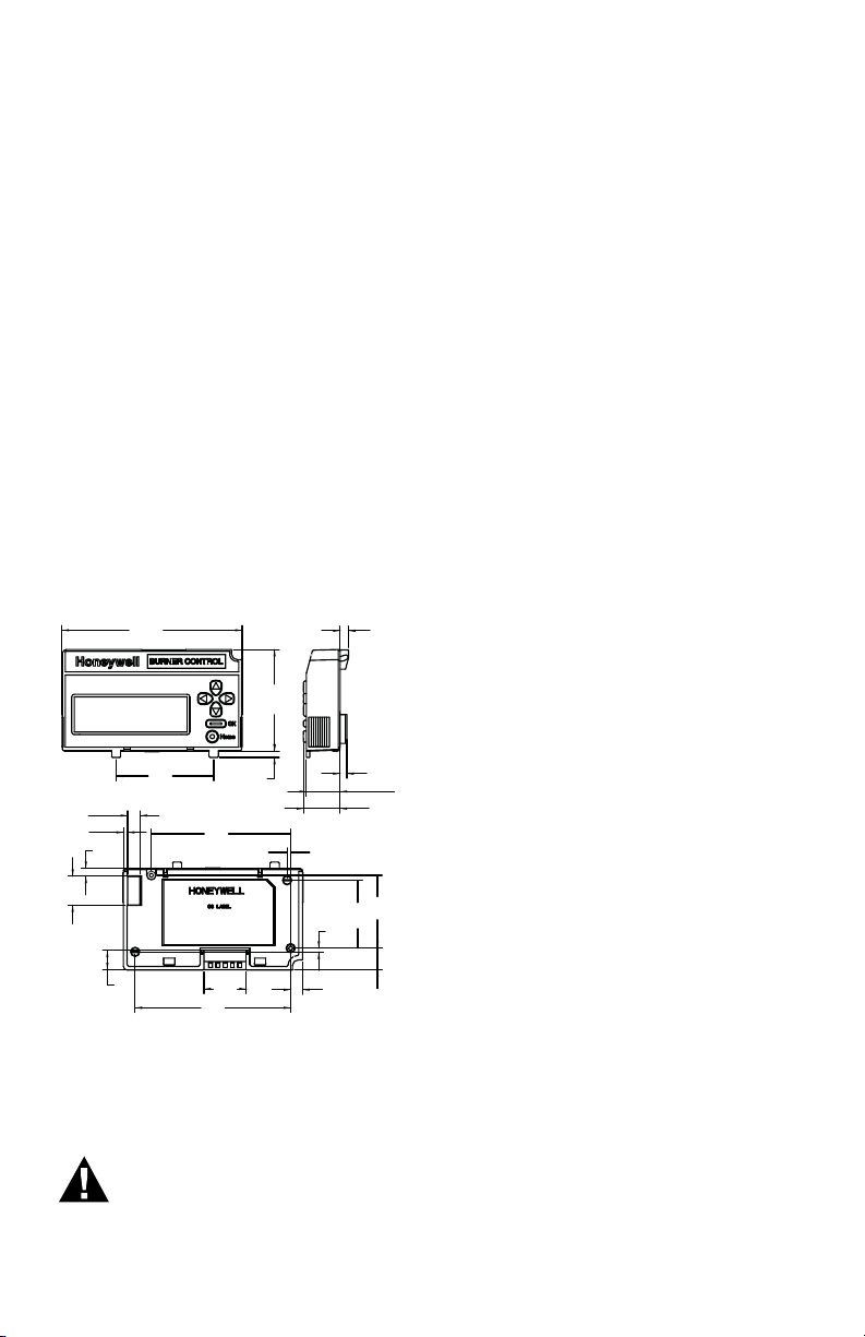
Dimensions: See Fig. 1.
Weight: 4 oz. (124 grams), unpacked.
Display:
5 rows by 64 columns with title and
navigation bar.
Languages:
S7800A2142 English/Spanish/French
Language display.
Approvals:
Underwriters Laboratories Inc. Listed: File
No. MP268, guide No. MCCZ.
Factory Mutual Approved: Report No.
J.I.1V9A0.AF. IRI: Acceptable.
Federal Communications Commission: Part
15, Class B emissions.
outputs.
SERIES.
204729A,C NEMA 4 Cover is used.
7800 SERIESS7800A2142 4Line LCD Keyboard Display Module
4.85
(123.3)
2.75
(69.8)
.17
(4.3)
2.63
(66.8)
.18
(4.6)
.91
(23.1)
.99
(25.1)
.22
(5.7)
.59
(15)
.32
(8.1)
3.76
(95.4)
.21
(5.4)
.78
(19.8)
.11
(2.9)
.34
(8.8)
.52
(13.2)
1.14
(29)
4.19
(106.4)
1.97
(50)
.10
(2.5)
.10
(2.4)
1.84
(46.7)
EN60730: For compliance with remote
KDM mounting require- ments, provide
electrical insulation separation by
insulation using double or reinforced
insulation. Do this by: Optically isolating the communication or remote
reset lines from the control cabinet, or
provide physical separation from the
communication or remote display cover
assembly (part number 204729A) or other
suitable enclosure that meets the IP40
class of protection.
Accessories:
203541 ControlBus™ 5-wire Electrical
Connector.
S7810A1009 Data ControlBus™ Module.
203765 Remote Display Mounting Bracket.
221818A 60 in. (1.5 m) Extension Cable
Assembly.
221818C 120 in. (3 m) Extension Cable
Assembly.
204729A NEMA 4 Cover Assembly for
S7800A KDM.
204729C NEMA 4 Cover Assembly for
S7800A KDM with reset button.
205321B Remote Display Flush Mount Kit.
Disconnect the power supply before
beginning installation to prevent
electrical shock and equipment
damage. More than one power
supply disconnect can be involved.
When Installing This Product…
1. Read these instructions carefully.
Failure to follow them could damage the
product or cause a hazardous condition.
2. Check the ratings given in the
instructions and marked on the product
to make sure the product is suitable for
your application.
3. Installer must be a trained, experienced,
flame safeguard service technician.
4. After installation is complete, check out
the product operation as provided in
these instructions.
5. Be sure wiring complies with all
applicable codes, ordinances and
regulations.
6. See Fig. 3 for S7800A unique wiring
connections.
IMPORTANT
1. This equipment generates, uses and can
radiate radio frequency energy and, if not
installed and used in accordance with the
instructions, can cause interference to radio
communications. It has been tested and
found to comply with the limits for a Class
B computing device of Part 15 of FCC rules
which are designed to provided reasonable
protection against such interference when
operated in a commercial environment.
Operation of this equipment in a residential
area can cause interference, in which case,
users, at their own expense, can be required
to take whatever measures are required to
correct this interference.
2. This digital apparatus does not exceed
the Class B limits for radio noise for digital
Fig. 1. Approximate dimensions of S7800A2142
in. (mm).
INSTALLATION
WARNING
Electrical Shock Hazard.
Can cause severe injury, death
apparatus set out in the Radio Interference
Regulations of the Canadian Department of
Communications.
Humidity
Install the S7800A where the relative
humidity never reaches the saturation
point. The S7800 is designed to operate
in a maximum 85% RH continuous,
noncondensing, moisture environment.
Vibration
Do not install the S7800A where it can be
subjected to vibration in excess of 0.5G
continuous maximum vibration.
or property damage.
3 320011007

7800 SERIESS7800A2142 4Line LCD Keyboard Display Module
Temperature
Temperatures below 32 °F (0 °C) may cause
a slow screen refresh rate and ghosting.
This effect will be most evident during cold
start-up (display has not been operating
and is in a < 32 °F (0 °C) environment). This
is due to the time required for the display to
warm up. The display has a heater feature
which can be set to automatic/ON/OFF
(refer to page 42 Heater Mode)
If the display does not fully recover within 5
minutes, then check the systems line input
voltage to insure it is within specifications.
For certain RM/ EC7800xx models the
display heater (used to improve display
legibility in colder temperatures) will not be
available and will not function regardless
of what the setting is in the display module
Heater Mode.
Refer to page 43 Models that do not
use the Heater Function for a list of relay
models that do not use the heater function.
Weather
The S7800A is not designed to be weather
tight. If installed outdoors, the S7800A
must be protected by an approved
weather-tight enclosure such as the
204729A or 204729C NEMA 4 Enclosure
listed in Accessories.
S7800A2142 Embedded Features
See Appendix A to set up the following
features:
• Call Service (Business Card) information
displayed when burner system is in
Lockout of the 7800 SERIES device.
• Customizing of Expanded Annunciator
(S7830) message to match a given
installed limit string. If ModBus Feature
is required, use S7810M1003 ModBus
Module.
• ModBus communication setup and
enable feature: Note that this will
occupy terminals 1, 2, 3 of the 203541
Connector on the KDM, which disables
the Expanded Annunciator Features.
SERVICE NOTE:
The S7800A2142 can either do the
Expanded Annunciator Feature or
ModBus -- not both. If BOTH are
required, order the S7810M1003
ModBus Module for the ModBus
option.
B. The S7800A2142 KDM is also used to
program the Valve Prov- ing and Postpurge feature of Select RM7800 SERIES
devices. See Appendix B.
320011007 4
Mounting KDM on 7800 SERIES
Relay Module.
1. Align the two interlocking ears of the
KDM with the two mating slots on the
7800 SERIES Relay Module. See Fig. 2.
Fig. 2. Keyboard Display Module mounting.
2. Insert the two interlocking ears into
the two mating slots and, with a hinge
action, push on the lower corners of the
KDM to secure it to the 7800 SERIES
Relay Module.
3. Make sure the KDM is firmly in place.
Remote Mounting KDM
The KDM can be mounted either on the
face of a panel door or on other remote
locations. When mounting the KDM on the
face of a door panel, closely follow these
instructions:
1. Select the location on the door panel for
flush mounting.
2. Pay attention to the insertion
dimensions of the two KDM screws, two
interlocking ears, and the two plugin connections to allow for sufficient
clearance.
3. Use the KDM or Data ControlBus
Module™ as a template (Fig. 28)
and mark the two screw locations,
interlocking ear locations and the two
plug-in connector locations.
4. Drill the pilot holes for the mounting
screws.
5. Cut holes in the door panel for the
interlocking ears and the two plug-in
connectors.
6. Mount the KDM, securing it with the
two screws provided in the KDM bag
assembly.
Remote Display Mounting Bracket
Use the 203765 Remote Display Mounting
Bracket when mounting the KDM on a wall
or remote location:
7800 SERIESS7800A2142 4Line LCD Keyboard Display Module
1. Use the 203765 Remote Display
Mounting Bracket as a template to mark
the four screw locations.
2. Drill the pilot holes for the four
mounting screws.
3. Mount the 203765 Remote Display
Mounting Bracket by securing the four
no. 6 screws (M3.5 x 0.6).
4. Mount the KDM by aligning the two
interlocking ears with the two mating
slots on the remote mounting bracket.
5. Insert the two interlocking ears into the
two mating slots.
6. Push on the lower corners of the KDM
to secure it to the remote mounting
bracket.
7. Make sure the KDM is firmly in place.
WIRING
WARNING
Electrical Shock Hazard.
Can cause severe injury or
death.
To prevent electrical shock and
equipment damage, disconnect
the power supply from the main
disconnect before beginning
installation. More than one
disconnect can be involved.
1. Refer to Fig. 3 for proper wiring.
2. Make sure all wiring complies with all
applicable electrical codes, ordinances
and regulations.
3. For recommended wire size and type,
see Table 1.
4. For Recommended grounding practices,
see Table 2.
5. For KDM: The KDM is powered from a
low voltage, energy- limited source. It
can be mounted outside of a control
panel if it is protected from mechanical
damage.
NOTE: A 13 Vdc power supply must be
used any time more than one
KDM is used. A maximum of two
KDM, Data ControlBus™ Modules
or S7810B Multi-Drop Switch
Modules are allowed in any
combination.
Application
Keyboard Display Module
Data ControlBus™ Module
Remote Reset
Module
Communications
Interface
ControlBus
Module™
13 Vdc full
wave rectified
transformer
power input.
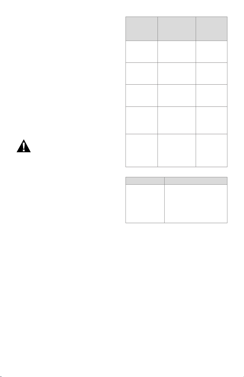
Table 1. Recommended Wire Size and Part Number.
Recommend-
ed Wire Size
22 AWG twowire twisted pair
with ground, or
five-wire.
22 AWG twowire twisted pair
with ground, or
five-wire.
22 AWG twowire twisted pair,
insulated for low
voltage.
22 AWG two-wire
twisted pair with
ground.
18 AWG wire,
insulated for
voltages and
temperatures for
given applications.
Ground Type Recommended Practice
Signal ground
(KDM, Data ControlBus™ Module,
Communications Interface
ControlBus
Module™).
Table 2. Recommended Grounding Practices.
Use the shield of the signal
wire to ground the device to
the signal ground terminals
[3(c)] of each device. Connect the shield at both ends
of the daisy chain to ground.
6. Recommended wire routing:
a. ControlBus:
(1) Do not route the ControlBus cable
in conduits that carry line voltage
circuits.
(2) Avoid routing the ControlBus cable
close to ignition transformer leadwires.
(3) Route the ControlBus cable outside
of conduit if properly supported and
protected from damage.
b. Remote Reset:
(1) Do not run high voltage ignition
transformer wires in the same conduit
with the Remote Reset wiring.
(2) Do not route Remote Reset wires in
conduit with line voltage circuits.
Recommended
Part Num-
ber
Belden 8723
shielded
cable or
equivalent.
Belden 8723
shielded
cable or
equivalent.
—
Belden 8723
shielded
cable or
equivalent.
TTW60C,
THW75C,
THHN90C
7. Maximum wire lengths:
(a) KDM: The maximum length
interconnecting wire is 4000 ft
(1219m).
5 320011007
7800 SERIESS7800A2142 4Line LCD Keyboard Display Module
S7810 DATA CONTROLBUS MODULEª
A CABINET DOOR.
(b) Remote Reset leadwires: The
maximum length wire is 1000 ft
(MOUNTED ON 7800 SERIES RELAY MODULE)
(300m) to a Remote Reset pushbutton.
8. Install all electrical connectors.
1
9. Restore power to the panel.
KDM Display
The first line of the KDM display provides
current status of the burner sequence
(STANDBY, PURGE, PILOT IGN, MAIN IGN,
RUN and POSTPURGE), timing information
(PURGE, PILOT IGN, MAIN IGN and
POSTPURGE) in minutes and seconds, hold
information (PURGE HOLD), and lockout
information (Lockout, Fault Code, Message
and Sequence). The second line will display
selectable or preemptive messages. A
selectable message supplies information
for flame strength, system status
indication, system or self-diagnostics and
troubleshooting. A preemptive message
has parentheses around the message and
supplies a detailed message to support the
sequence status information. A preemptive
message can also be a lockout message. A
preemptive message replaces a selectable
message to support the sequence status
information. The 7800 SERIES Relay
Module LED provide positive visual
indication of the Relay Module sequence.
The LED is energized simultaneously with
the correct sequence description.
1
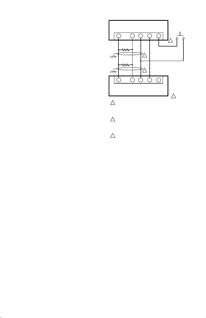
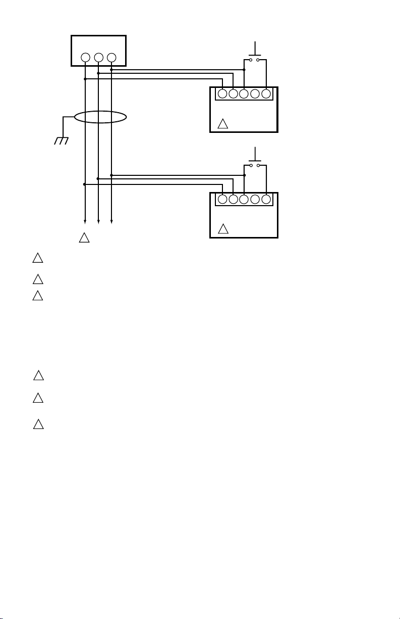
THREE WIRE SHIELDED CABLE MAY BE REQUIRED. TWO 120
1
OHM TERMINATING RESISTORS ARE REQUIRED FOR
CONNECTIONS OVER 100 FEET. CABLE SHIELD MUST BE
TERMINATED TO EARTH GROUND AT BOTH ENDS. IF SHIELDED
CABLE IS NOT USED, TWISTED PAIR WIRE MUST BE USED.
2
WHEN CONNECTING THE KEYBOARD DISPLAY MODULE DATA
CONTROLBUS MODULEª, OR REMOTE RESET MODULE
EXTERNAL FROM THE CONTROL CABINET, APPROPRIAT E
MEASURES MUST BE TAKEN TO MEET EN60730 SAFETY
LOW VOLTAGE REQUIREMENTS (SEE APPROVALS).
3
221818A OR C EXTENSION CAN BE USED IN PLACE OF THE
S7810 DATA CONTROLBUS MODULEª IF DISPLAY IS TO
Fig. 3. Wiring Keyboard Display Module for remote
mounting.
A
B
C (GND)
2345
120 OHM
RESISTOR
120 OHM
RESISTOR
2345
A
B
C (GND)
7800 REMOTE KEYBOARD DISPLAY MODULE
RESET
+13 VDC
1
1
RESET
+13 VDC
MOMENTARY
PUSH BUTTON
SWITCH
3
2
M5285C
320011007 6
7800 SERIESS7800A2142 4Line LCD Keyboard Display Module
23
23
B
C (GND)
23
23
B
C (GND)
MOMENTARY
PUSHBUTTON
SWITCH
5
4
5
4
+13 VDC
RESET
MOMENTARY
PUSHBUTTON
SWITCH
5
4
5
4
+13 VDC
RESET
RM78xx SERIES DEVICE
WITH S7800 SERIES 5
OR GREATER DISPLAY.
RM78xx SERIES DEVICE
WITH S7800 SERIES 5
OR GREATER DISPLAY.
PC/PLCGND
-
+
B
1
MULTI-DROP RS-485 COMMUNICATION BUS. UP TO 31 S7800 SERIES 5 OR GREATER DISPLAYS CAN BE CONNECTED TO A SINGLE BUS
1
WITHOUT AN RS-485 REPEATER. UP TO 99 MODBUS™ (SUBNETWORKS) CAN BE CONNECTED TO A BUS WITH RS-485 REPEATERS. WHEN
USING AN RS-485 REPEATER, THE REPEATER MUST BE INSTALLED EVERY 30TH MODULE.
THE SUBNETWORKS MUST BE WIRED IN A DAISY CHAIN CONFIGURATION. RECOMMEND THAT THE PC/PLC BE AT ONE END OF THE
2
DAISY CHAIN.
MODBUS™ COMMUNICATION BUS TERMINATION RESISTORS:
3
A. WITHOUT RS-485 REPEATER:
MODULES AT THE CLOSEST AND FARTHEST END OF THE DAISY CHAIN REQUIRE TERMINATION RESISTORS.
INSTALL A 120 OHM, 1/4 WATT RESISTOR BETWEEN TERMINALS A AND B OF THE PC/PLC (IF INSTALLED AT ONE END THE DAISY CHAIN).
INSTALL A 120 OHM, 1/4 WATT RESISTOR BETWEEN TERMINALS 7 AND 8 OF THE LAST S7810M MODBUS™ MODULE IN THE DAISY CHAIN.
B. WITH RS-485 REPEATER:
WHEN AN RS-485 REATER IS USED, TWO DAISY CHAIN CONFIGURATIONS ARE EFFECTIVELY FORMED. MODULES AT THE
CLOSEST AND FARTHEST ENDS OF EACH DAISY CHAIN REQUIRE TERMINATION RESISTORS. INSTALL A 120 OHM, 1/4 WATT
RESISTOR BETWEEN TERMINALS A AND B OF THE PC/PLC (IF INSTALLED AT THE END OF THE DAISY CHAIN. INSTALL A 120
OHM, 1/4 WATT RESISTOR BETWEEN INPUT TERMINALS DATA+ AND DATA- OF THE RS-485 REPEATER. INSTALL A 120 OHM,
1/4 WATT RESISTOR BETWEEN TERMINALS 7 AND 8 OF THE LAST S7810M MODBUS™ MODULE IN THE ADDITIONAL DAISY CHAIN.
LOCAL RS-485 COMMUNICATIONS BUS. THE DEVICES ON THIS BUS MUST BE WIRED IN A DAISY CHAIN CONFIGURATION. THE ORDER OF
4
INTERCONNECTION IS NOT IMPORTANT. THE MODULES ON THE CLOSEST AND FARTHEST ENDS OF THE DAISY CHAIN REQUIRE A 120 OHM,
1/4 WATT TERMINATION RESISTOR BETWEEN TERMINALS 1 AND 2 OR A AND B.
THREE WIRE SHIELDED CABLE (BELDEN 8723 SHIELDED OR EQUIVALENT) IS RECOMMENDED AND SHOULD BE GROUNDED AS
5
FOLLOWS: IF NO INTERFERENCE IS PRESENT, OR TO REDUCE CAPA CITIVE INTERFERENCE, THE SHIELD SHOULD BE GROUNDED
AT ONE END. WHEN GROUNDING ONLY ONE END OF THE THE SHIELD, THE SHIELD END CLOSEST TO THE S7810M MODBUS™
MODULE SHOULD BE ATTACHED TO EARTH GROUND. TO REDUCE INDUCTIVE INTERFERENCE (RF INTERFERENCE), THE SHIELD
SHOULD BE GROUNDED AT BOTH ENDS.
6
TERMINAL NUMBERS ARE ON 203541 5-WIRE CONNECTOR (SUPPLIED WITH REMOTE MOUNTING BRACKET).
RS-485
BUS
CA
1
1
A
6
1
1
A
6
M24190
Fig. 4. Wiring for ModBusTM Feature.
NOTE: LED has been replaced by block characters visible on the MB address setup menu.
7 320011007
7800 SERIESS7800A2142 4Line LCD Keyboard Display Module
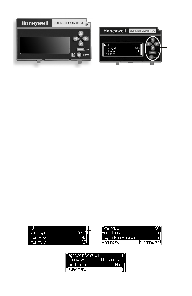
KEYBOARD
4 LINES
LINE WITH
doesn’t make sense for the button action,
selecting the button is ignored.
BUTTONS
Fig. 5. S7800 Keyboard Display Module
Keyboard Functions
The keyboard contains six push-buttons
that are used to navigate on each page and
between pages on the display module (see
Fig. 6). These buttons generally have the
following functions:
• Up arrow - move up on a page or
increment a value for an input control
• Down arrow - move down on a page or
decrement a value for an input control
• Left arrow - move to the left on a page
(tab left) or go to a previous page
• Right arrow - move to the right on a page
(tab right) or go to the next page when
applicable
• OK - approve/accept the highlighted item
or go to the next page when applicable
• Home - go to the Home (Main Status)
page
When the burner control module is in a
Lockout condition the “Home” button
navigates to the Lockout page instead of
the Home page to display the lockout.
These buttons are acted on when they
are pressed and released. In some cases
a button can be pressed and held, i.e., not
released, for repeated execution of the
button (arrow buttons). Buttons are active
on some pages only when the action for the
button makes sense for the position of the
input focus on the page. If the input focus
Fig. 6. Keyboard buttons.
Page Structure
The Home and Lockout pages display text
using a larger font size than all other pages
so that information on them can be more
easily viewed from distances farther away
from the display module (see Fig. 7 and Fig.
8).
Up to 4-5 lines of text are displayed
(dependent on font size) at a time on the
page. When the page has more than 4 lines
of text to display a scroll bar is present on
the right-hand side of the page to indicate
this situation. The “Up arrow” and “Down
arrow” buttons are used to scroll up and
down the lines of the page. Each line is
highlighted with a white background to
indicate that it currently has input focus for
any button actions. The scroll bar adjusts to
give a relative position of the current view
with respect to all lines that the page can
display.
When a line has a right arrow symbol
positioned on the righthand side it
indicates that this line can navigate to
another page, “Next page”, related to the
subject of the line when that line has input
focus. A “Right arrow” or “OK” button can
be pressed when the focus is on this line to
navigate to the next page.
Fig. 7. Home page
320011007 8
SCROLL
BAR
RIGHT ARROW SYMBOL INDICATES
“NEXT” PAGE IS AN OPTION
INPUT
FOCUS
7800 SERIESS7800A2142 4Line LCD Keyboard Display Module
4 LINES
TION
BAR
W INPUT
MENU
GO TO
LOCKOUT
DETAIL
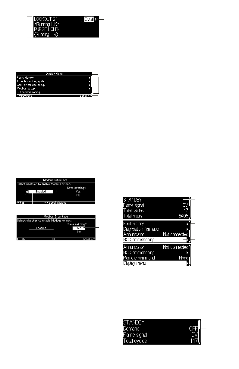
Fig. 8. Lockout page
For pages other than Home and Lockout a
smaller font size is used to display the text
and pages have a format like the one shown
in Fig. 9.
TITLE BAR
MAIN
BODY
NAVIGA
Fig. 9. Page structure
The top line of the page is a title that
describes the context or purpose of the
page (see Fig. 9).The bottom line of the
page is a navigation bar which indicates
the more important button actions that can
be performed for the current input focus
(see Fig. 10). The middle or main body
of the page contains the lines that show
information or allow for user input. Up to 5
lines of text may be displayed in the main
body. Solid lines separate the title and
navigation bar from the main body.
INPUT FOCUS
Home Page
The Home page is the main status page
that displays primary status of the burner
control operation (see Fig. 11). This page is
intended to be the primary one displayed
most often when the user is not specifically
looking for other information or configuring
the display. The following information is
displayed by default:
• Burner control sequence or lockout state
• Flame signal strength
• Total cycles count
• Total run-time hours count
• Annunciator connection status
• Remote command status
The burner control sequence state may
be displayed in one or two lines due to the
length of the text. In case of two lines the
remaining lines are pushed down to make
room for the second line.
This page also permits navigation to the
following pages:
• Lockout message (when burner control is
in a lockout condition)
• Fault history
• Burner control diagnostic status
• Annunciator diagnostic status (when
annunciator is connected)
• Burner control commissioning
(supported models only)
• Display menu
MAY BE 1 OR 2
LINES (SEQUENCE
STATE)
NE
FOCUS
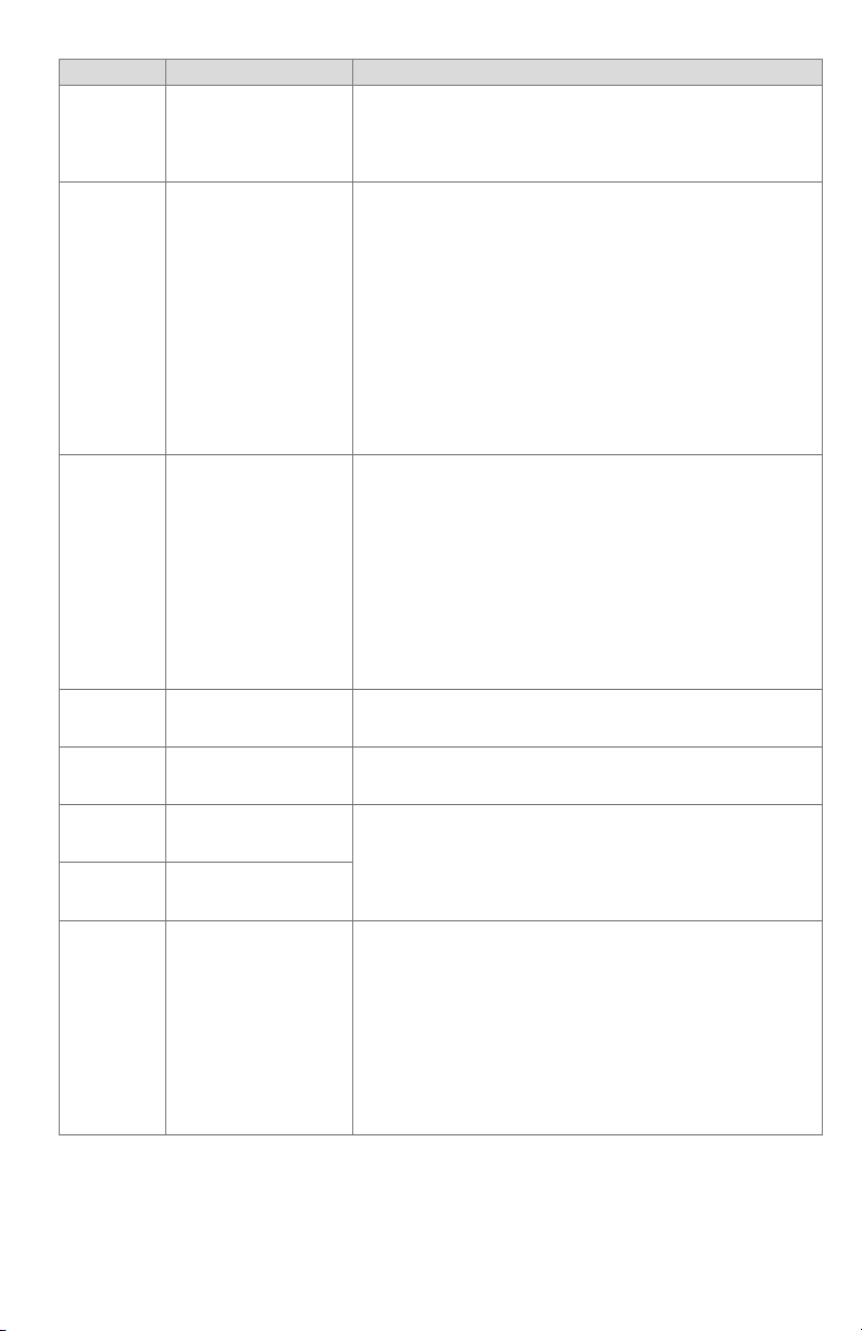
Fig. 10. Input focus
An item on a page that has input focus
is usually highlighted with an inverse
look (black text on white background) to
distinguish it from the rest of the page.
The arrow buttons move the input focus
to another selectable item if another one
exists on the page (some pages may only
have a single focus item).
For pages that allow user input (see Fig.
10) the input value is edited on the page
and then is acknowledged or confirmed at
another tab position on the page (“Yes” tab
Fig. 11. Home page status
An additional status line can be displayed
between the burner control sequence line(s)
and the flame signal strength line when
configured (see “Selected Status Message”
on page 30). Fig. 12 shows an example
with the T6 terminal (“Demand”) status
displayed.
in the above example). This confirmation
action permits the user to cancel the editing
and not commit to the change or to accept
the edited value.
Fig. 12. Home page status
9 320011007
GO TO FAULT
HISTORY
GO TO BURNER
DIAGNOSTICS
GO TO
COMISSIONING (ONLY
SOME MODELS)
GO TO DISPLAY
OPTIONAL
SELECTED
STATUS

7800 SERIESS7800A2142 4Line LCD Keyboard Display Module
The lines are scrollable using the up and down arrows. For lines that navigate to another
page the right arrow or OK button is pressed when the line has input focus (highlighted) to
go to the new page.
TROUBLESHOOTING
After the KDM is installed, return the 7800 SERIES to normal operation, restore power
and run the system through at least one complete automatic cycle. For complete
Troubleshooting and System Checkout information, see form 65-0229.
7800 SERIES System Diagnostics
Troubleshooting control system equipment failures is made easier with the 7800 SERIES
self-diagnostics and first-out annunciation. The S7800 provides visual annunciation by
displaying a fault code and fault or hold message on the display.
Self-diagnostics of the 7800 SERIES enables it to detect and annunciate both external
and internal system problems. Internal faults and external faults such as interlock failures,
flame failures and false flame signals are annunciated by the KDM via the 7800 SERIES
Relay Module.
The KDM displays a sequence status message indicating STANDBY, PREPURGE, PREIGNITION, SAFETY 1, PILOT IGN, PILOT STAB., MAIN IGN, RUN or POSTPURGE, as
appropriate. The selectable messages also provide visual indication of current status and
historical status of the equipment, such as: Flame Signal, Total Cycles, Total Hours, Fault
History, Diagnostic Information and Expanded Annunciator terminal status (if used).
With this information, most problems can be diagnosed without extensive trial-and-error
testing.
Table 3 provides the sequence and status hold messages. These messages along with the
fault messages (Table 5) can be viewed on-line in the KDM.
320011007 10
7800 SERIESS7800A2142 4Line LCD Keyboard Display Module
Sequence Status
The Keyboard Display Module (KDM) indicates the burner status, INITIATE, a
stabilization period for the relay module to check for any fluctuations in ac line
INITIATE mm:ss
voltage inputs or control inputs on power up or during normal operation. The
timing of the INITIATE period is either two seconds or ten seconds, depending
on the model, before entering STANDBY.
If the relay module is in an INITIATE HOLD status, the following conditions could exist:
The KDM indicates the burner status and that it is waiting for excess line noise
INITIATE HOLD:
(AC Frequency/
Noise)
to clear up, which prevents sufficient reading of the line voltage inputs. The
burner sequence does not advance into STANDBY until the excess line noise
ceases or a line frequency error occurs; this is caused by using a 60 Hz device
on a 50 Hz line, or vice versa on devices with a date code earlier than 9804, is
corrected.
INITIATE HOLD:
(AC Line Dropout)
The KDM indicates the burner status and that ac line power has momentarily
dropped out. The burner sequence does not advance into STANDBY until the ac
line voltage has stabilized throughout the INITIATE sequence.
The KDM indicates the burner status and that line frequency is faster than the
INITIATE HOLD:
(AC Frequency)
expected value. The burner sequence does not advance into STANDBY until the
line frequency returns to the proper value; this is perhaps caused by using a 60
Hz device on a 50 Hz line for devices with a date code earlier than 9804.
INITIATE HOLD:
(Low Line Voltage)
The KDM indicates the burner status and that low line voltage (10% lower
than rated voltage) has occurred. The burner sequence does not advance
into STANDBY until the line voltage is at a sufficient level for proper operating
parameters.
The KDM indicates the burner status, STANDBY. The burner can be placed in
STANDBY by opening the burner switch or if the operating controller indicates
STANDBY
its setpoint is satisfied. If a demand is present for burner operation, the burner
sequence does not advance from STANDBY to PURGE until the recycle limits
close. If an Expanded Annunciator is connected, the display messages are
enhanced.
If the relay module is in a STANDBY HOLD status, the following conditions could exist:
STANDBY HOLD:
F/G (Flame
Detected)
STANDBY HOLD:
T20(Pre-Ignition
Interlock)
STANDBY HOLD:
T7(Lockout
Interlock)
STANDBY HOLD:
T7 (Running
Interlock) EC/
RM7850
The KDM indicates the burner status and that a flame is detected. A demand
is present for burner operation. The sequence does not advance to PREPURGE
until the flame signal clears. If the flame signal does not clear within 40 sec-
onds, the relay module locks out.
The KDM indicates the burner status and that the Pre-Ignition Interlock is not
closed. A demand is present for burner operation, but the burner sequence does
not advance to PREPURGE until the Pre-Ignition Interlock proves closed. If this
time exceeds a 30 second hold, the relay module locks out.
The KDM indicates the burner status and that the Lockout Interlock is closed.
A demand is present for burner operation, but the burner sequence does not
advance to PREPURGE until the Lockout Interlock proves open. If this time
exceeds the 120 second hold, the relay module locks out.
The KDM indicates the burner status and that the Running Interlock is closed.
A demand is present for burner operation, but the burner sequence does not
advance to PREPURGE until the Running Interlock proves open. If this time
exceeds the 120 second hold, the relay module locks out.
The KDM indicates the burner status, PURGE, which is the period of time the
PURGE
blower motor is running before the Ignition period. The timing of the PURGE
period is selectable.
If the relay module is in a PURGE HOLD status, the following conditions could exist:
PURGE HOLD:
T19 (High Fire
Switch)
PURGE DELAY:
T19 (High Fire
Switch Jumpered)
PURGE HOLD:
TEST (Run/Test
Switch)
11 320011007
The KDM indicates the burner status and that the High Fire Switch is not closed.
The firing rate motor is driving to its PURGE rate position. If this time exceeds
four minutes and fifteen seconds, the relay module locks out.
The KDM indicates the burner status and that the High Fire Switch is jumpered.
The High Fire Switch is bypassed, welded or otherwise prematurely closed. The
system automatically adds 30 seconds to allow the firing rate motor additional
drive time to reach or near the open damper position before starting the PURGE
sequence.
The KDM indicates the burner status and that the Run/Test Switch is in the
TEST position. The sequence does not continue until the Run/Test Switch is
placed in the RUN position.
7800 SERIESS7800A2142 4Line LCD Keyboard Display Module
Sequence Status
PURGE HOLD:
T18 (Low Fire
Switch Jumpered)
PURGE HOLD:
F/G(Flame Detected)
PURGE HOLD:
T18 (Low Fire
Switch)
PURGE HOLD:
T7 (Running
Interlock)
PILOT IGN
mm:ss
The KDM indicates the burner status and that the Low Fire Switch is jumpered.
The Low Fire Switch is bypassed, welded or otherwise prematurely closed. The
system automatically adds 30 seconds to allow the firing rate motor addition-
al drive time to reach or near the closed damper position before starting the
ignition sequence.
The KDM indicates the burner status and that a flame is detected. The burner
sequence does not advance through PREPURGE because a flame is detected
as being present. The sequence holds waiting for the flame signal to clear. If the
time exceeds 30 seconds, the relay module locks out.
The KDM indicates the burner status and that the Low Fire Switch is not closed.
The firing rate motor is driving to its Low Fire position in preparation for Ignition
Trials. If this time exceeds four minutes and fifteen seconds, the relay module
locks out.
The KDM indicates the burner status and that the Running Interlock is not
closed. The sequence does not advance to ignition until the Running Interlock
proves closed. If this time exceeds 30 seconds, the relay module locks out.
The KDM indicates the burner status, PILOT IGN, and the timing of the PILOT
IGN trial begins, in seconds. During this period, the relay module permits the
pilot valve to open and the pilot flame to establish.
If the relay module is in a PILOT HOLD status, the following conditions could exist:
PILOT HOLD:
TEST (Run/Test
Switch)
The KDM indicates the burner status, PILOT IGN, and that the Run/Test Switch
is in the TEST position. The sequence does not continue until the Run/Test
Switch is placed in the RUN position.
The KDM indicates the burner status, MAIN IGN, and the timing of the MAIN
MAIN IGN mm:ss
IGN trial begins, in seconds. During this period, the relay module permits the
main valve to open and the main flame to establish.
The KDM indicates the burner status, RUN, which is the period of time after the
RUN
Ignition Trials and before the operating controller setpoint is reached. During
this time, the burner is firing under control of the firing rate control.
If the relay module is in a RUN HOLD status, the following condition could exist:
RUN LOWFIRE:
TEST (Run/Test
Switch)
POSTPURGE
mm:ss
Waiting for connection...
The KDM indicates the burner status and that the Run/Test Switch is in the
TEST position. Normal modulation or operation does not continue until the
Run/Test Switch is placed in the RUN position.
The KDM indicates the burner status, POSTPURGE, which is the period of time
after the RUN period when the blower motor continues to run. The timing of the
POSTPURGE period is fifteen seconds.
The KDM has power but is waiting to receive a signal from the relay module to
continue operation.
The KDM indicates the burner status, RESET/ALARM TEST. This condition inRESET/ALARM
TEST
dicates that the reset button is pressed. If it is held for more than four seconds,
the alarm output is energized. The alarm output is de-energized when the reset
button is released.
Additional Sequence Status Information When An Expanded Annunciator is Connected to the
Relay Module:
BURNER OFF: T6
(Burner Switch)
The KDM indicates the Burner Switch is not closed. The burner sequence does
not advance to PREPURGE until the Burner Switch closes.
The KDM indicates the burner status, STANDBY, and that the Operating Control
STANDBY
is not closed. The burner sequence does not advance to PREPURGE until the
Operating Control closes.
STANDBY HOLD:
T6 (EA Hold
Message)
STANDBY HOLD:
T6 (Circuit Fault)
Table 3. Keyboard Display Module Sequence and Status Hold Messages .
The KDM indicates the burner status, STANDBY, and that a limit is not closed.
The burner sequence does not advance to PREPURGE until one or all limits
close downstream from the Operating Control.
The KDM indicates the burner status, STANDBY, and that the control input is not
closed. The burner sequence does not advance to PREPURGE until the control
input closes.
320011007 12
7800 SERIESS7800A2142 4Line LCD Keyboard Display Module
The S7800 provides diagnostic information to aid the service mechanic in obtaining
information when troubleshooting the system. See Table 4 for information on accessing
historical and diagnostic selectable messages. Information available in the Diagnostic
Information includes Device Type, Software Revision, Manufacturing Code, Flame Amplifier
Type, Flame Failure Response Time (FFRT), Selectable Jumper Configuration Status, Run/
Test Switch Status and Terminal Status.
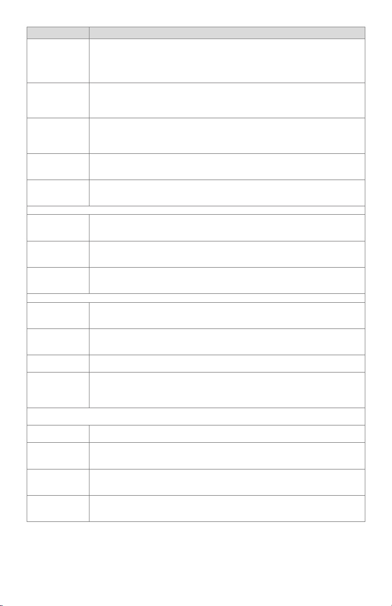
Information from the above table and Table 5 are viewable in the display module. The
troubleshooting guide can be accessed from the Display Menu (see Fig. 13). A menu is
displayed that permits access to these different sections of the guide:
• Introduction
• Faults
• Sequence and Status Hold messages
Fig. 13. Troubleshooting guide menu
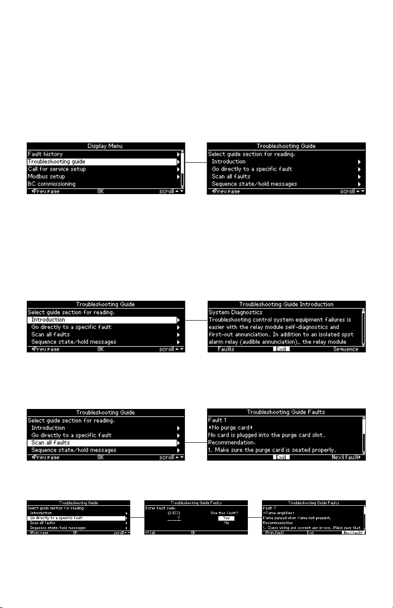
The Introduction section contains brief troubleshooting tips and is presented in a scrollable
paragraph form for reading using the up and down arrow buttons (see Fig. 14). The
navigation bar contains the following commands that can be selected using the right and
left arrow buttons:
• “Faults” – go to Troubleshooting guide Faults section
• “Exit” – exit Introduction section and return back to Troubleshooting guide menu
• “Sequence” – go to Troubleshooting guide Sequence/Status Hold section
Pressing the OK button executes the command with the current input focus.
Fig. 14. Troubleshooting guide introduction
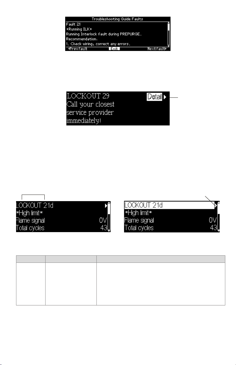
The Faults section presents a description and recommended actions for each fault that
the burner control module may have (see Fig. 15). The information is presented for a single
fault code and when more lines are needed to display the information than can fit on the
page, the up and down arrow buttons are used to scroll through the lines.
Fig. 15. Troubleshooting guide faults section
The Faults section can be accessed starting at the beginning (see Fig. 15) or by going
directly to a specific fault code (see Fig. 16).
Fig. 16. Troubleshooting guide direct fault access
13 320011007
7800 SERIESS7800A2142 4Line LCD Keyboard Display Module
The Faults navigation bar contains the following commands that can be selected using the
right and left arrow buttons:
• “Prev fault” – go to previous fault code
• “Exit” - exit Faults section and return back to Troubleshooting guide menu
• “Next fault” – go to next fault code
Pressing the OK button executes the command with the current input focus.
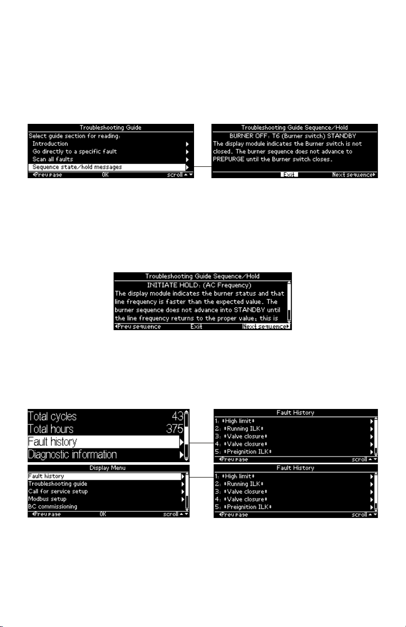
The Sequence and Status Hold section explains the meaning of different sequence state
and status hold messages that can display for a burner control on the display module (see
Fig. 17). The up and down arrow buttons are used to scroll the lines of the explanation.
Fig. 17. Troubleshooting guide sequence section
The Sequence/Status Hold navigation bar (see Fig. 18) contains the following commands
that can be selected using the right and left arrow buttons:
• “Prev sequence” – go to previous sequence/status hold message
• “Exit” - exit Sequence/Status Hold section and return back to Troubleshooting guide
menu
• “Next sequence” – go to next sequence/status hold message
Pressing the OK button executes the command with the current input focus.
Fig. 18. Troubleshooting guide sequence section (continued)
Historical Information Index
The S7800 displays historical information for the six most recent lockouts. Each of the six
lockout records retains the cycle when the fault occurred, a fault code, a fault message, and
burner status when the fault occurred. The fault history can be accessed from either the
Home or Display Menu pages (see Fig. 19).
Fig. 19. Fault history menu
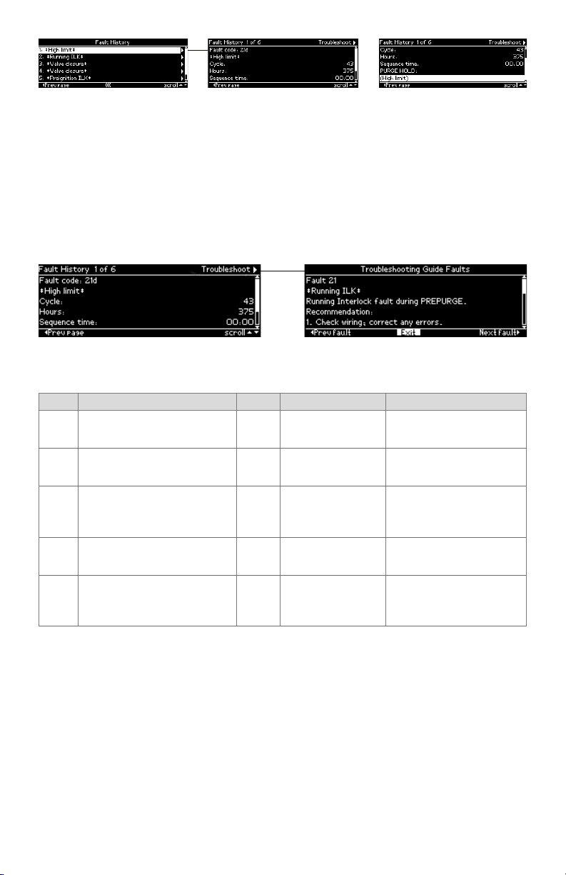
The fault history is displayed in order from most recent lockout, #1, on the first line to the
oldest lockout on the last line. The up and down arrow buttons are used to scroll to the
lockout desired and the right arrow or OK button is pressed to view the fault information
(see Fig. 20) for that lockout.
320011007 14
7800 SERIESS7800A2142 4Line LCD Keyboard Display Module
Fig. 20. Fault history record
The fault record is scrollable using the up and down arrow buttons to see all lines of the
information. The fault description can take 1 or 2 lines to display and is presented on the
line(s) below the fault code line. Below the sequence time line is displayed the sequence
state that the burner control was in at the time of the fault. This state description may take
1 or 2 lines to display also.
The left arrow button can be pressed to exit this fault record and go back to the Fault
history menu (previous page).
The title bar displays which fault history record is displayed and indicates that the
Troubleshooting guide can be navigated to using the “Next page” (right arrow) button (see
Fig. 21).
GO TO
TROUBLESHOOTING
GUIDE
Fig. 21. Troubleshooting guide from fault history record
When the “Exit” command in the troubleshooting guide has input focus and the OK button
is pressed control returns back to the fault history record.
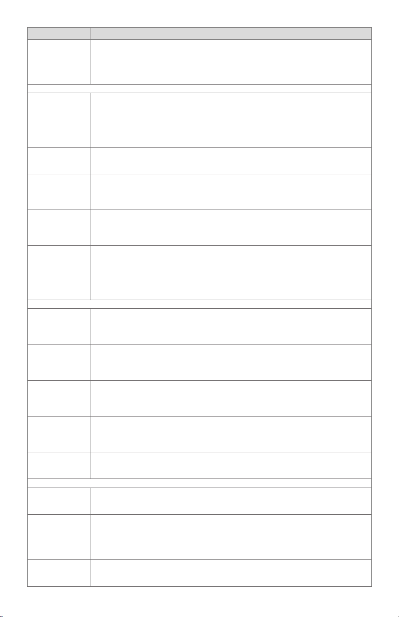
Step Operation Press Display Comments
Press hi buttons to access
1.
Diagnostic Information.
Press u button to access Diag-
2.
nostic Information.
hi
t u
STANDBY Diagnostic Information>
STANDBY Diagnostic Information>
Use the Down/Up arrow
buttons to access the "Diagnostic information" line.
Use the right arrow or OK
button to access the Diagnostic Information.
Push the Down/Up arrow
Continue display of Diagnostic
3.
Information.
hi
Device RM7800<
buttons to scroll through
the burner control diagnostic status.
Continue through remaining
4.
diagnostic information display
— — —
following step 3 as required.
Another display can be
Press the t arrow button to
5.
return to the Home page
t u
STANDBY Diagnostic Information>
selected or discontinue
accessing Diagnostic Information review.
Table 4. Accessing Historical and Diagnostic Selectable Messages.
SERVICE NOTE: If the Keyboard Display Module screen is scrambled, remove and reinstall
the Keyboard Display Module and reset the 7800 SERIES Relay Module.
SERVICE NOTE: Reset the 7800 SERIES Relay Module by pressing the reset push button
on the relay module or pressing a remote reset push button wired through the
Keyboard Display Module, Data ControlBus™ Module or Remote Reset Module. A
power-up reset will cause an electrical reset of the 7800 SERIES Relay Module but
will not reset a lockout condition.
Lockout Messages
When the 7800 SERIES is locked out, a standard lockout message is displayed unless the
Call for Service feature is enabled. When the Call for Service feature is enabled a custom
lockout message is displayed instead. The standard lockout message (see Fig. 22) is
automatically displayed when the lockout initially occurs unless the user happens to be
15 320011007

7800 SERIESS7800A2142 4Line LCD Keyboard Display Module
ANNUNCIATED
editing a parameter on a page. In this case the lockout message waits until the user is done
editing and exits the page.
FAULT CODE
DESCRIPTION
STATE AT TIME
OF FAULT
GO TO
LOCKOUT
DETAIL
Fig. 22. Lockout message
Up to 4 lines are displayed in the standard lockout message. The top line shows the
numeric fault code that determined the lockout. A description of this fault is shown on the
second line and possibly on the third line if the description requires two lines to display
it (only one line needed in the above example). On the next line(s) the burner control
sequence state at the time of the lockout is displayed. The sequence state may need 1 or 2
lines to display (Fig. 22 required two lines). Since a maximum of 4 lines are displayed in this
message, in the case when both the fault description and sequence state each need 2 lines
to display their text, the second line of the sequence state is dropped to make room.
FAULT CODE
ANNUNCIATED
DESCRIPTION
Fig. 23. Annunciated lockout message
When an annunciator is connected to the burner control system it may annunciate the
lockout to provide more detailed information regarding the lockout. In this case the fault
code is annunciated with a fault code letter and the fault description identifies more
specifically the cause of the fault (see Fig. 23 for an example).
On the top line of the message the input focus is on a flashing “Detail” tab that permits
the user to view more details about the lockout. Pressing the “Right arrow” or “OK” button
navigates to a Lockout Detail page (see the following figure) that provides the following
information:
• Fault code
• Fault description
• Cycle count at the time of the fault
• Run-time hours at the time of the fault
• Sequence time at the time of the fault
• Operation sequence state at the time of the fault
Fig. 24. Lockout detail
The information may take more lines to display than can fit on the 5 main body lines. In this
case the a scroll bar is displayed, and the up and down arrow buttons can be used to scroll
to view all lines.
A flashing “Troubleshoot” tab is displayed in the title bar that has input focus to indicate
that the troubleshooting guide can be navigated to display what is recommended for this
fault (see Fig. 25).
320011007 16
7800 SERIESS7800A2142 4Line LCD Keyboard Display Module
LOCKOUT
Fig. 25. Troubleshooting guide
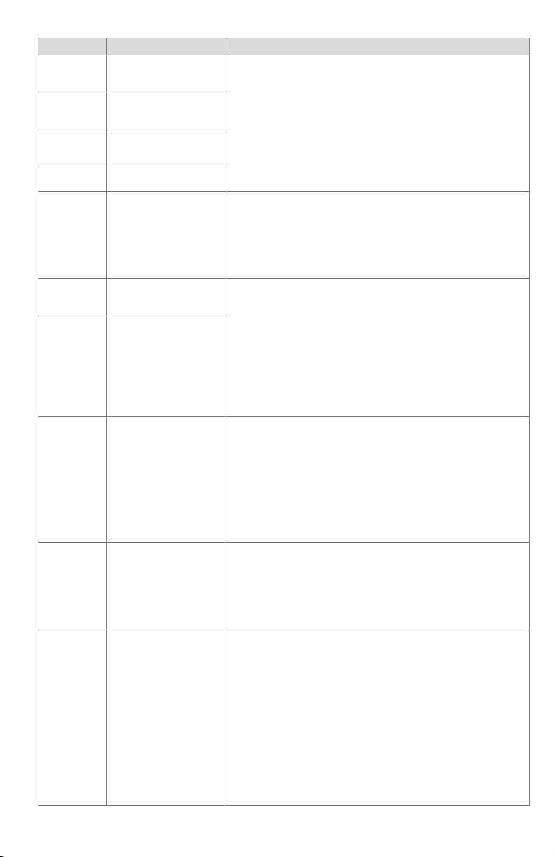
When the Call for Service feature is enabled a custom message up to 8 lines is displayed
instead of the standard lockout message (see Fig. 26 for an example). Only 4 lines of the
custom message are displayed at a time; the first 4 lines are displayed for 2 seconds,
followed by the remaining lines for 2 seconds. The page alternates between these two sets
of lines continuously. If the custom message is 4 lines or less, no alternation is needed.
GO TO
LOCKOUT
DETAIL
Fig. 26. Call for Service lockout message
The first or top line of the message is not custom and is the same as the top line in the
standard lockout message. This line permits the user to navigate to the Lockout Detail
page.
The lockout message (standard or custom) displays continuously while the lockout
condition persists. The user may elect to exit the message to view other pages by pressing
the “Left arrow” or “Home” button which navigates to the Home page. The lockout
condition is displayed on the Home page (see Fig. 27) which permits the user to re-display
the lockout message. Pressing the “Right arrow” button when the lockout fault code line
has input focus causes the lockout message to be re-displayed.
C0NDITION
GO TO
LOCKOUT
MESSAGE
Fig. 27. Lockout indication on Home page
The following table describes the possible faults a burner control may have and the
recommended action.
Fault Code System Failure
Make sure the purge card is seated properly.
Inspect the purge card and connector on the relay module for
damage or contaminants.
Fault 1 *No
Purge Card*
No card is plugged into
the purge card slot.
Reset and sequence the relay module.
If the fault code reappears, replace the purge card.
Reset and sequence the relay module.
f the fault persists, replace the relay module.
17 320011007
7800 SERIESS7800A2142 4Line LCD Keyboard Display Module
Fault Code System Failure
Fault 2 *AC
Frequen/
Noise*
Fault 3 *AC
Line Dropout*
Fault 4
*AC Frequency*
Fault 5*Low
Line Voltage*
Excess noise or device
running on slow AC.
AC line dropout detected.
Device running on fast
AC.
Low AC line detected.
Check the relay module and display module connections.
Reset and sequence the relay module.
Check the relay module power supply and make sure that
both frequency and voltage meet the specifications.
Check the backup power supply, as appropriate.
Make sure the purge card is seated properly.
Inspect the purge card and connector on the relay module for
Fault 6
*Purge Card
Error*
Purge card timing
changed since card was
initially read.
damage or contaminants.
Reset and sequence the relay module.
If the fault code reappears, replace the purge card.
Reset and sequence the relay module.
If the fault persists, replace the relay module.
Fault 7
*Flame Amplifier*
Flame sensed when
flame not present.
Check wiring and correct any errors. Make sure that flame
sensor wires are in separate conduits. Check for noise cou-
pling into the flame detector leadwires.
Make sure that flame detector and flame amplifier are com-
patible.
Fault 8
*Flame Amp/
Shutter*
Flame sensed when no
signal expected during
shutter-check or Ampli-Check versions.
Remove the flame amplifier and inspect connections. Reseat
the amplifier.
Reset and sequence the relay module.
If the code reappears, replace the amplifier and/or the flame
detector.
If the fault persists, replace the relay module.
Check that flame is not present in the combustion chamber;
correct any errors.
Check wiring and correct any errors. Make sure that flame
Fault 9
*Flame
Detected*
Flame sensed when
shutter open and no
flame is expected
during STANDBY.
sensor wires are in separate conduits. Check for noise cou-
pling into flame detector leadwires.
Remove the flame amplifier and inspect its connections.
Reseat the amplifier. Reset and sequence the relay module.
If the code reappears, replace the amplifier and/or the flame
detector.
If the fault persists, replace the relay module.
Check wiring and correct any errors.
Fault 10
*Pre-Ignition
ILK*
Pre-Ignition Interlock
fault during STANDBY
*(EC/RM7800, 7840,
7838B only).
Check Pre-Ignition Interlock switches to assure proper func-
tioning.
Check fuel valve operation.
Reset and sequence the relay module; monitor the Pre-Igni-
tion Interlock status.
If the code persists, replace the relay module.
Check wiring to make sure that interlocks are connected
properly between terminals 6 and 7. Correct any errors.
Reset and sequence the relay module.
If the fault persists, measure the voltage between terminals 6
and G (ground), then terminals 7 and G. If there is line supply
Fault 11
*Running ILK
On*
Running Interlock
powered at improper
sequence point.
voltage present at terminal 6 when the controller is off, the
controller switch may be bad or is jumpered.
If steps 1 through 3 are correct and there is line supply volt-
age present at terminal 7 when the controller is closed and
the fault persists, check for a welded or jumpered Running
Interlock, Lockout Interlock, or Airflow Switch. Correct any
errors.
If steps 1 through 4 are correct and the fault persists, replace
the relay module.
320011007 18

Fault Code System Failure
Fault 12
*Lockout ILK
On*
Fault 13
*Airflow Sw.
On*
Fault 14
*High Fire
Sw.*
Fault 15
*Flame
Detected*
Fault 16
*Flame-Out
Timer*
Fault 17
*Main Flame
Failure*
Fault 18
*Flame
Detected*
Lockout Interlock powered at improper point
in sequence.
Combustion airflow
interlock fault during
STANDBY.
High Fire Interlock
Switch failure to close
during PREPURGE.
Flame sensed when
no flame is expected
during STANDBY.
No flame detected
during Pilot Flame
Establishing Period.
Main flame failure
during RUN after flame
is established and on
for at least 10 seconds.
Flame sensed when
shutter is open and
no flame is expected
during PREPURGE.
7800 SERIESS7800A2142 4Line LCD Keyboard Display Module
-
-
Check wiring and correct any errors.
Reset and sequence the relay module.
Use either the manual motor potentiometer to drive the motor
to the High Fire position or use the Run/Test Switch option, if
available. Sequence to Prepurge drive to High Fire and place
in the Test position. Adjust the High Fire Switch while in this
state to make sure that it closes properly.
Measure the voltage between terminal 19 and G (ground)
while in the Prepurge drive to High Fire state. Line supply
voltage should be present. If not, the switch adjustment is
incorrect and/or the switch is defective and needs replacing.
Reset and sequence the relay module. If line supply voltage
was present between the High Fire Switch and terminal 19,
and the fault still persists, replace the relay module.
Check that the flame is not present in the combustion cham-
ber; correct any errors.
Make sure that the flame amplifier and flame detector are
compatible.
Check wiring and correct any errors.
Remove the flame amplifier and inspect the connections.
Reseat the amplifier.
Reset and sequence the relay module.
If the code reappears, replace the amplifier and/or the flame
detector.
If the fault persists, replace the relay module.
Measure the flame signal. If one exists, make sure it meets
specifications.
Make any necessary burner adjustments using manufacturer
instructions. Make sure that the flame amplifier and flame
detector are compatible.
If the code reappears, replace the amplifier and/or the flame
detector.
If the fault persists, replace the relay module.
Inspect the main fuel valve(s) and connection(s).
Make sure that the fuel pressure is high enough to supply fuel
to the combustion chamber.
Check the flame detector sighting for adequate flame signal
throughout the burner firing rate.
Check that flame is not present in the combustion chamber.
Correct any errors.
Make sure that the flame amplifier and flame detector are
compatible.
Check the wiring and correct any errors. Make sure F and
G wires are in individual conduits and protected from stray
noise pickup.
Remove the flame amplifier and inspect the connectors.
Reseat the flame amplifier.
Reset and sequence the relay module.
If the code reappears, replace the flame amplifier and/or the
flame detector.
If the fault persists, replace the relay module.
19 320011007
7800 SERIESS7800A2142 4Line LCD Keyboard Display Module
Fault Code System Failure
Fault 19
*Main Flame
Ignition*
Flame was lost during
MFEP or the first 10
seconds of the RUN
state.
Inspect the main fuel valve(s) and connection(s).
Make sure that the fuel pressure is high enough to supply fuel
to the combustion chamber.
Make sure the flame detector is positioned to obtain the
required flame signal strength; reset and recycle.
Check wiring and correct any errors.
Reset and sequence the relay module.
Use either the manual motor potentiometer to drive the motor
to the Low Fire position or use the Run/Test Switch option, if
available. Sequence to Prepurge drive to Low Fire and place in
Fault 20
*Low Fire
Switch Off*
Low Fire Interlock
switch failure to close
during PREPURGE.
the Test position. Adjust the Low Fire Switch to make sure that
it closes properly.
Measure the voltage between terminal 18 and G (ground)
while in the Prepurge drive to Low Fire state. Line supply
voltage should be present. If not, the switch adjustment is
incorrect and/or the switch is defective and needs replacing.
Reset and sequence the relay module. If line supply voltage
was present between the Low Fire Switch and terminal 18,
and the fault still persists, replace the relay module.
Check wiring; correct any errors.
Inspect the fan; make sure there is no blockage of the air
intake and that it is supplying air.
Make sure the Interlock Switches are working properly and
Fault 21
*Running
ILK*
Running Interlock fault
during PREPURGE.
that all switch contacts are free of contaminants.
Reset and sequence the relay module to PREPURGE (place
the
Run/Test Switch in the Test position, if available). Measure
the voltage between terminals 7 and G (ground). Line voltage
should be present.
If steps 1 through 4 are correct and the fault persists, replace
the relay module.
Fault 22
*Lockout
ILK*
Fault 23 *Airflow Switch*
Fault 24 *Internal fault*
Fault 25 *Internal fault*
Lockout Interlock fault
during PREPURGE.
Combustion airflow
interlock fault during
PREPURGE.
The flame interlock
(relay module) was on
when it should be off.
The flame interlock
(relay module) was off
when it should be on.
-
-
Check for F leadwire routing. Make sure routing is in its con-
duit and isolated from noise-producing circuits.
Check wiring and correct any errors.
Make sure that the Manual Open Valve Switch is fully open.
Make sure that the Manual Open Valve Switch is functioning
Fault 26
*Man-Open
Sw. Off*
The Manual Open
Valve Switch was off
when it should be on
(RM7838B only).
properly and that the switch contacts are free from contam-
inants.
Reset and sequence the relay module.
Make sure that the Manual Open Valve Switch provides an
electrical path when closed. Verify that the relay module is
receiving power at terminal 17.
If steps 1 through 5 are correct and the fault persists, replace
the relay module.
320011007 20
Loading...