


RTH5160 Series
Non-Programmable
Thermostat
Quick Installation Guide
Included in your box
Screws and anchors
RTH5160 Thermostat
UWP™  Mounting
System
(UWP)
Quick Install Guide
Tools you will need |
Tools you may need |
Phillips screwdriver
Small flat head screwdriver |
Wire stripper |
|
|
|
|
||
Pencil |
Needle-nose pliers |
Drill and |
|
drill bit (7/32 in) |
|||
|
|
Level
Quick Installation Guide
Removing your old thermostat
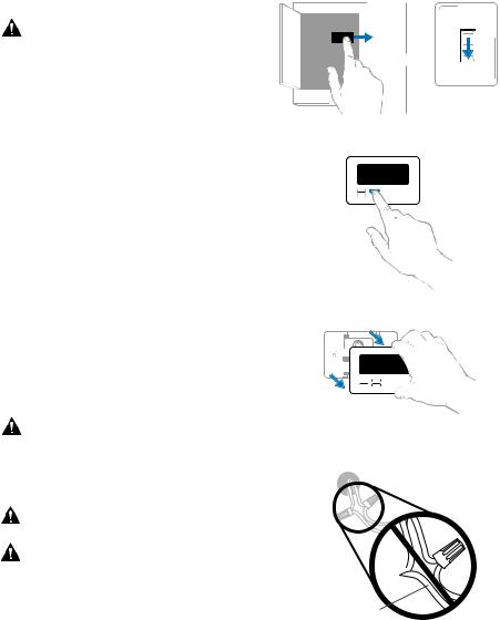
1 Turn power OFF.
To protect yourself and your equipment, turn off the power at the breaker box or the switch that controls your heating/cooling system.
ON
OR
OFF
Switch
Breaker box
2Check that your system is off.
Change the temperature on your old thermostat to be above room temperature in heat mode or below it in cool mode. If you don’t hear the system turn on within 5 minutes, the power is off.
Note: If you have a digital thermostat that has a blank display, skip this step.
3Remove the old thermostat’s faceplate.
On most thermostats, you can take off the faceplate by grasping and gently pulling. Some thermostats may have screws, buttons, or clasps.
Do not remove any wires from your thermostat at this time!
4Make sure there are no 120/240V wires.
Do you have thick black wires with wire nuts?
Is your thermostat 120V or higher?
If you answered yes to either of these questions, you have a line voltage system and the thermostat will not work.
75
Wire nut  Thick black wire
2

RTH5160 Series
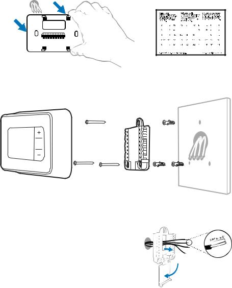
5 Take a picture of how your wiring looks right now.
Be sure to include the letters next to the terminals where the wires are inserted. This will be a helpful reference when wiring your new thermostat.
Tip: If the color of your wires has faded or if 2 terminals have the same wire color, use the wire labels provided in the package to label each wire.
6Record which R-wire(s) you have and write down the color of the wire(s).
Note: Do not include jumpers as a part of your count. The thermostat does not need jumpers.
Terminal Wire Color |
Example of |
|
R |
|
a jumper |
|
||
Rh |
|
|
Rc |
|
Terminals |
7Record the remaining wires and write down the color of the wires.
Check mark the wires that are connected to terminals. Next to the check mark, write down the color of the wire. Do not include jumpers as a part of your count.
Check all that apply (Not all will apply):
Terminal |
Wire Color |
Terminal |
Wire Color |
Y |
|
A or L/A |
|
G |
|
O/B |
|
|
|
||
C |
|
W2 or AUX |
|
|
|
||
|
|
E |
|
|
|
|
|
|
|
W |
|
|
|
|
|
|
|
K |
|
|
|
|
|
|
|
|
|
NOTES:
•C does not power the thermostat display or operations; batteries are always required.
•If K was used on old thermostat you have a wire-saver at the equipment. Re-wiring would need to be done so that Y and G are used instead of K.
•The RTH5160 thermostat does not support L/A, S, or U terminals.
•If there are wires in terminals that are not listed, you will need additional wiring support. Visit yourhome.honeywell.com/support to find out if the thermostat will work for you.
3
Quick Installation Guide
8Disconnect the wires and remove the old wall plate.
Use a screwdriver to release wires from terminals. Then, use a wire label to identify each wire as it’s disconnected. The letter on the wire label should match the letter on the terminal.
Tip: To prevent wires from falling back into the wall, wrap the wires around a pencil.
Installing your RTH5160 thermostat
RTH5160 |
|
UWP |
|
|
Screws |
Mounting Anchors |
Wall |
||
Thermostat |
||||
|
System |
|
||
|
|
|
9 Bundle and insert wires through the UWP.
Pull open the UWP and insert the bundle of wires through the back of the UWP.
Make sure at least 1/4 inch of each wire is exposed for easy insertion into the wire terminals.
4
RTH5160 Series
10 Insert the wall anchors.
It is recommended that you use the wall anchors included in the box to mount your thermostat.
You can use the UWP to mark where you want to place the wall anchors.
a) Level the wall plate.
b) Mark the location of the wall anchors using a pencil.
c) Drill the holes.
d) Insert wall anchors.
e) Make sure anchors are flush with wall.
Tip: Use a 7/32 drill bit.
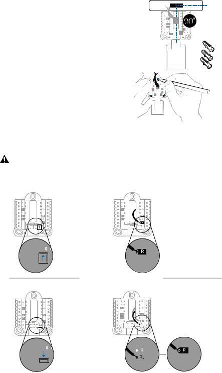
11Set R-switch position and insert R-wire(s).
Set the R-switch up or down based on your wiring notes in Step 6.
Insert wires into the inner holes of the terminals on the UWP. The tabs will stay down once the wire is inserted.
NOTE: Alternate wiring options are shown on pages 11-12.
If you have 1 R-wire (R, Rh, or Rc) |
|
1. Set R-switch |
2. Insert your |
to the up |
R-wire (R, Rh |
position. |
or Rc) into |
|
R-terminal. |
or
If you have 2 R-wires (R or Rh, and Rc)
1. Set R-switch to the down position.
2.Insert your Rc wire into Rc-terminal
3.Insert your R or Rh wire into R-Terminal.
5
Quick Installation Guide
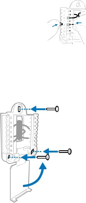
12Connect remaining wires.
Depress the tabs to put the wires into the inner holes of the corresponding terminals on the
UWP (one wire per terminal) until it is firmly in place.
Gently tug on the wires to verify they are secure.
Tip: If you need to release a wire again, push down the corresponding terminal tab on the side of the UWP.
NOTE: Alternate wiring options are shown on pages 11-12.
This wiring is just an example, yours may vary.
13Confirm wiring matches snapshot.
Please confirm wiring matches terminals from the photo you took in Step 5.
14Mount the UWP and close the door.
Mount the UWP using the provided screws. Install all three screws for a secure fit on your wall. Close the door after you’re finished.
Use 3x supplied screws #8 1-1/2”
6
RTH5160 Series
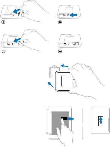
15Install batteries.
Insert two AA alkaline batteries in the back of the thermostat as shown.
16 Attach your thermostat.
Align the thermostat onto the UWP and firmly snap it into place.
17 Turn your power ON. |
|
|
Turn on the power at the breaker box |
ON |
|
or switch that controls the heating/ |
ON |
|
cooling system. |
||
|
||
|
OR |
|
|
OFF |
|
|
Switch |
|
|
Breaker box |
7
Quick Installation Guide
System Setup
Now that you have installed your thermostat, please follow the steps below to setup your system and personalize your thermostat.
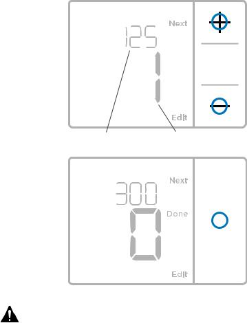
18Select System Setup options.
Press Edit (-) to change values or select from available options. Then press Next (+) to save changes and advance to the next System Setup number.
See “System Setup options” on the next page for a full list of System Setup numbers and options.
Repeat until all of the System Setup options have been set, and then press Done. The thermostat will save and exit to the home screen.
19Continue to “System operation settings” on page 10.
Setup number |
Option number |
|
|||||
|
|
|
|
|
|
|
|
|
|
|
|
|
|
|
|
|
|
|
|
|
|
|
|
|
|
|
|
|
|
|
|
|
|
|
|
|
|
|
|
|
|
|
|
|
|
|
|
NOTE: To re-enter the System Setup from the Home Screen, press and hold the Menu button for approximately 5 seconds.
8
|
|
RTH5160 Series |
|
System Setup options |
|
||
|
|
|
|
System Setup Number and Description |
|
Options (factory default in bold) |
|
|
|
||
125 = Temperature Indication Scale |
0 = Fahrenheit |
||
1 |
= Celsius |
||
|
|||
|
1 |
= Conventional Forced Air Heat |
|
|
2 |
= Heat Pump |
|
200 = Heating System Type |
3 |
= Radiant Heat (Boiler) |
|
5 = None (Cool Only) |
|||
|
Note: This option selects the basic system type your thermostat will |
||
|
control. |
||
|
Conventional Forced Air Heat: |
||
|
1 |
= Standard Efficiency Gas Forced Air |
|
|
2 |
= High Efficiency Gas Forced Air |
|
|
3 |
= Oil Forced Air |
|
|
4 |
= Electric Forced Air |
|
|
5 |
= Hot Water Fan Coil |
|
205 = Heating Equipment Type |
Heat Pump: |
||
7 |
= Air to Air Heat Pump |
||
|
|||
|
Radiant Heat: |
||
|
9 |
= Hot Water Radiant Heat |
|
|
12 = Steam |
||
|
Note: This option selects the equipment type your thermostat will |
||
|
control. This feature is NOT displayed if feature 200 is set to Cool Only. |
||
|
0 |
= O (O/B in Cool) |
|
218 = Reversing Valve O/B |
1 |
= B (O/B in Heat) |
|
Note: This option is only displayed if the Heat Pump configured. Select |
|||
|
|||
|
whether reversing valve O/B should energize in cool or in heat. |
||
|
|
||
|
0, 1, 2 |
||
220 = Cool Stages / Compressor Stages |
|
|
|
Note: Select how many Cool or Compressor stages of your equipment |
|||
(200=Conv / 200=HP) |
|||
the thermostat will control. Maximum of 2 Cool stages or 1 Compressor |
|||
|
|||
|
stage. Set value to 0 if you do not have Cool Stage/Compressor Stage. |
||
|
|
||
|
Heat Stages: 1, 2 |
||
|
Backup Heat Stages: 0, 1 |
||
221 = Heat Stages / Backup Heat Stages |
Note: Select how many Heat or Aux/E stages of your equipment the |
||
thermostat will control. Maximum of 2 Heat Stages for conventional |
|||
|
|||
|
systems. Maximum of 1 Aux/E stage for systems with more than 1 |
||
|
heating equipment type. Set value to 0 if you do not have Heat Stage/ |
||
|
Backup Heat Stage. |
||
|
0 |
= Manual |
|
|
1 |
= Automatic |
|
300 = System Changeover |
Note: Thermostat can automatically control both heating and cooling |
||
|
to maintain the desired indoor temperature. To be able to select |
||
|
“automatic” system mode on thermostat home screen, turn this feature |
||
|
ON. Turn OFF if you want to control heating or cooling manually. |
||
NOTE: Once you have cycled through all of the System Setup numbers, press Done to save and exit to the home screen.
Setup Complete
You have now finished installing and setting up your thermostat.
9
Quick Installation Guide
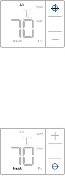
System operation settings
1Press Menu, and then press the Mode (+) button to cycle to the next available System mode.
2Cycle through the modes until the required System mode is displayed, and then press Done.
NOTE: Available System modes vary by model and system settings.
System modes:
‒‒ Auto: Thermostat selects heating or cooling as needed.
‒‒ Heat: Thermostat controls only the heating system.
‒‒ Cool: Thermostat controls only the cooling system.
‒‒ Em Heat (only for heat pumps with auxiliary heat): Thermostat controls Auxiliary Heat. Compressor is not used.
‒‒ Off: Heating and cooling system is off. Fan will still operate if fan is set to On.
NOTE: Heat On/Cool On may flash for 5 minutes due to compressor protection.
Fan operation settings
1Press Menu, and then press the Fan (-) button to cycle to the next available Fan mode.
2Cycle through the modes until the required Fan mode is displayed, then press Done.
NOTE: Available Fan modes vary with system settings.
Fan modes:
‒‒ Auto: Fan runs only when the heating or cooling system is on.
‒‒ On: Fan is always on.
10
 Loading...