


Owner’s
Guide
RLV4305
Programmable Thermostat

Table of contents
Overview |
|
About your new thermostat ................................................................... |
1 |
Controls ................................................................................................. |
2 |
Display................................................................................................... |
3 |
Installation |
|
Installation guidelines ............................................................................ |
4 |
Wiring .................................................................................................... |
5 |
Thermostat mounting ............................................................................ |
6 |
Clock and day setting ............................................................................ |
7 |
Operation |
|
Automatic (Auto) mode.......................................................................... |
8 |
Manual (Man) mode ............................................................................ |
10 |
Away mode.......................................................................................... |
10 |
Standby mode ..................................................................................... |
10 |
Appendices |
|
Advanced settings ............................................................................... |
11 |
In case of difficulty............................................................................... |
14 |
Resetting the thermostat (default settings).......................................... |
15 |
Power outage ...................................................................................... |
16 |
Specifications ...................................................................................... |
16 |
Limited warranty .................................................................................. |
17 |

RLV4305
About your new thermostat
This thermostat is designed to control an electric heating system such as a baseboard heater, a radiant ceiling, a convector or a fan-forced heater.
The thermostat CANNOT be used with:
•a resistive load under 0.83 A
•a resistive load over 14.6 A
•a system driven by a contactor or a relay (inductive load)
•a central heating system
SUPPLIED PARTS
•One (1) thermostat
•Two (2) 6-32 mounting screws
•Two (2) solderless connectors
Do you need assistance?
We are here to help.
Call 1-800-468-1502.
1
Owner’s Guide
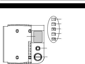
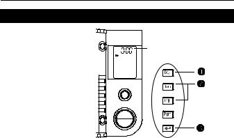
Controls
|
Day button |
|
|
Hour button |
|
|
Minute button |
|
Backlit screen * |
Program button |
|
Return button |
||
|
||
|
Mode button |
|
|
(see pages 8 & 10) |
|
|
Up and Down buttons |
* The screen is backlit for 12 seconds when you press any button.
2
RLV4305
Display
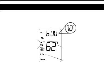
|
|
Time and day |
|
|
Setpoint |
|||||||
|
|
|
|
|
|
|
|
|
|
|
||
|
|
|
|
|
|
|
|
|
|
|
temperature * |
|
Appears when power to |
||||||||||||
|
|
|
||||||||||
the thermostat is cut off |
Indicates that the settings |
|||||||||||
(see page 7) |
|
|
|
|
|
|
|
|
||||
|
|
|
|
|
are locked (see page 11) |
|||||||
|
|
|
|
|||||||||
Appears if the |
Room temperature |
|||||||||||
thermostat is configured |
|
|
|
|
|
|
|
Heating intensity indicator |
||||
|
|
|
||||||||||
for a fan-forced heater |
|
|
|
|
|
|
|
|
||||
(see page 11) |
|
|
|
Mode indicator |
||||||||
|
||||||||||||
|
|
|
|
(see pages 8 & 10) |
||||||||
Period indicator |
||||||||||||
(see page 8) |
|
|
|
|||||||||
*To display the set temperature (setpoint), press the Up or Down button once. The thermostat will display the setpoint instead of the clock for 5 seconds.
3

Owner’s Guide
Installation guidelines
TURN OFF POWER TO THE HEATING SYSTEM AT THE MAIN POWER PANEL TO AVOID ELECTRICAL SHOCK.
All cables and connections must comply with local electrical codes.
This thermostat has tinned copper wires for line and load connections. Special CO/ALR solderless connectors must be used if these wires will be connected to aluminium conductors.
Install the thermostat onto an electrical box.
Install the thermostat about 5’ (1.5 m) high, on an inside wall facing the heater.
Avoid locations where there are air drafts (such as the top of a staircase or an air outlet), dead air spots (such as behind a door), or direct sunlight.
Do not install the thermostat on a wall that conceals chimney or stove pipes.
The thermostat wires are not polarized; either wire can be connected to the load or to the power supply.
4

RLV4305
Wiring
Connect the thermostat wires to the power and to the load using solderless connectors for copper wires.
2-wire Installation |
|
4-wire Installation |
||||||||||||||||||||||||||||
|
|
|
|
|
|
|
|
|
|
|
|
|
|
|
|
|
|
|
|
|
|
|
|
|
|
|
|
|
|
|
|
|
|
|
|
|
|
|
|
|
|
|
|
|
|
|
|
|
|
|
|
|
|
|
|
|
|
|
|
|
|
|
|
|
|
|
|
|
|
|
|
|
|
|
|
|
|
|
|
|
|
|
|
|
|
|
|
|
|
|
|
|
|
|
|
|
|
|
|
|
|
|
|
|
|
|
|
|
|
|
|
|
|
|
|
|
|
|
|
|
|
|
|
|
|
|
|
|
|
|
|
|
|
|
|
|
|
|
|
|
|
|
|
|
|
|
|
|
|
|
|
|
|
|
|
|
|
|
|
|
|
|
|
|
|
|
|
|
|
|
|
|
|
|
|
|
|
|
|
|
|
|
|
|
|
|
|
|
|
|
|
|
|
|
|
|
|
|
|
|
|
|
|
|
|
|
|
|
|
|
|
|
|
|
|
|
|
|
|
|
|
|
|
|
|
|
|
|
|
|
|
|
|
|
|
|
|
|
|
|
|
|
|
|
|
|
|
|
|
|
|
|
|
|
|
|
|
|
|
|
|
|
|
|
|
|
|
|
|
|
|
|
|
|
|
|
|
|
|
|
|
|
|
|
|
|
|
|
|
|
|
|
|
|
|
|
|
|
|
|
|
|
|
|
|
|
|
|
|
|
|
|
|
|
|
|
|
|
|
|
|
|
|
|
|
|
|
|
|
|
|
|
|
|
|
|
|
|
|
|
|
|
|
|
|
|
|
|
|
|
|
|
|
|
|
|
|
|
|
|
|
|
|
|
|
|
|
|
|
|
|
|
|
|
|
|
|
|
|
|
|
|
|
|
|
|
|
|
|
|
|
|
|
|
|
|
|
|
|
|
|
|
|
|
|
|
|
|
|
|
|
|
|
|
|
|
|
|
|
|
|
|
|
|
|
|
|
|
|
|
|
|
|
5

Owner’s Guide
Thermostat mounting
1)Push the excess wires back inside the electrical box.
2) Secure the thermostat to the electrical box using the provided screws.
3) Insert the screws through either the right or left pair of mounting holes on the thermostat.
NOTE: If there is a protective film or sticker on the thermostat’s screen, peel it off.
4)Apply power to the heating system. Verify the installation by checking that the heater can be turned on by raising the setpoint using the Up button and off by lowering the setpoint using the Down button.
WARNING: Keep the thermostat's air vents clean and free from obstructions.
6
RLV4305
Clock and day setting
1)Press the Day button to set the day.
2)Use the Hour and Min buttons to set the clock.
3)Press the 
 button to exit.
The clock must be set when the time is incorrect or flashes on the screen.
7
Owner’s Guide
Automatic mode
In Automatic mode, the thermostat adjusts its temperature setpoint according to the period of the day. To place the thermostat in this mode, press the Mode button until Auto appears on the screen. The current period name also appears (unless the thermostat has not been programmed with a schedule).
You can program up to 4 periods (Wake, Leave, Return or Sleep) in a day. You can set 2 different programs: one for the weekdays (Monday to Friday) and another one for the weekend (Saturday and Sunday).
The thermostat uses the following default schedule:
|
Monday to Friday |
Saturday & Sunday |
||
|
|
|
|
|
Period |
Start Time |
Temperature |
Start Time |
Temperature |
|
|
|
|
|
Wake |
6:00 am |
70°F (21.0°C) |
6:00 |
70°F (21.0°C) |
Leave |
8:00 am |
62°F (16.5°C) |
--:-- |
- - |
Return |
6:00 pm |
70°F (21.0°C) |
--:-- |
- - |
Sleep |
10:00 pm |
62°F (16.5°C) |
10:00 pm |
62°F (16.5°C) |
Temporary Override
You can temporarily modify the setpoint temperature while the thermostat is in Automatic mode using the Up or Down button. The new setpoint will be used until the beginning of the next period. During the override, Auto flashes on the screen.
You can cancel the override by pressing the 
 button.
8
RLV4305
Automatic mode (cont’d)
To modify the schedule:
1)Press the Pgm button. Each time you press
the Pgm button, the thermostat displays one of the periods of the schedule in the following order:
|
Weekdays |
|
|
Weekend |
|
||
(MO TU WE TH FR) |
|
(SA SU) |
|
||||
1 |
2 |
3 |
4 |
1 |
2 |
3 |
4 |
2) Press the Hour and Min buttons to set the start time of the displayed period.
NOTE: To cancel the period, press the Mode button. Instead of displaying the start time of the period, the thermostat will display --:--. During operation, the thermostat will skip over that period.
3)Press the Up or Down button to set the temperature.
4)To set another period, press the Pgm
button and repeat steps 2 and 3.
5)Press the 
 button to return to normal display.
9
Owner’s Guide
Manual (Man) mode
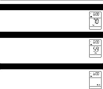
To place the thermostat in Manual mode, press the Mode button until Man appears on the screen. In this mode, any modification to the temperature setpoint must be done manually. To set the temperature, press the Up or Down button. The default setting is 70°F (21.0°C).
Away mode
To place the thermostat in Away mode, press the Mode button until Away appears on the screen. This mode is a quick way to lower the temperature to a predetermined setting before you go away for an extended length of time. The temperature is 59°F (15.0°C) by default and can be modified using the setup menu (see page 11).
Standby mode
To disable heating, press the Mode button until Standby appears on the screen. In this mode, the setpoint temperature cannot be displayed or modified. For frost protection, heating will turn on only to prevent the room temperature from dropping below 41°F (5°C).
10
 Loading...