


RTH6350D1000-E1
RedLINK™ Wireless System
With Equipment Interface Module
® U.S. Registered Trademark.
Copyright © 2011 Honeywell International Inc.
All rights reserved.
System
Installation
Guide
69-2091EFS-07
Wireless control for up to 3 Heat/2 Cool heat pump systems or up to 2 Heat/2
Cool conventional systems.
Installation guide for:
• Wireless equipment interface module
• FocusPRO
®
wireless thermostats
• Wireless remote control
• Wireless outdoor air sensor
• Return air sensor
DISCONNECT POWER BEFORE BEGINNING INSTALLATION. Can cause
electrical shock or equipment damage.
MERCURY NOTICE: If this product is replacing a control that contains mercury in
a sealed tube, do not place the old control in the trash. Contact your local waste
management authority for instructions regarding recycling and proper disposal.
Must be installed by a trained, experienced technician. Read these
instructions carefully. Failure to follow these instructions can damage the product or
cause a hazardous condition.
Français : voir la page 21 • Español: vea la página 41
RedLINK
TM
Installation Guide (EIM)
69-2091EFS—07 2
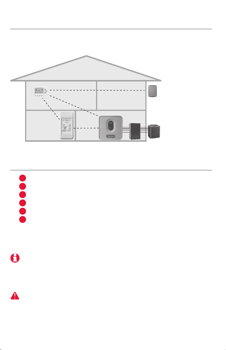
System installation at a glance
The THM5320R equipment interface module (EIM) provides control of all heating
and cooling equipment from any FocusPRO wireless thermostat.
Installation procedure
Mount and wire EIM .................................................................. Pages 3-4
Install batteries in wireless devices ...............................................Page 5
Link all devices to wireless network ........................................ Pages 5-7
Exit wireless setup ..........................................................................Page 8
Customize thermostat (installer setup) .................................. Pages 8-12
Mount thermostat and outdoor sensor .......................................Page 13
To replace system components if needed, see page 15
For system-specific wiring guides, see pages 16-17
If you have more than one Equipment Interface Module (EIM): Thermostats
are linked to specific EIMs. Optional accessories must be linked to each EIM
separately.
DISCONNECT POWER BEFORE BEGINNING INSTALLATION. Can cause electrical
shock or equipment damage.
Remote
control
Thermostat
Optional outdoor
air sensor
M28484
HVAC equipment
EIM
1
2
3
4
5
6
Français : voir la page 21 • Español: vea la página 41
3 69-2091EFS—07
M28494
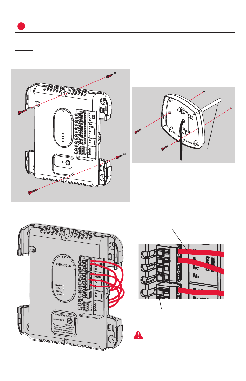
1
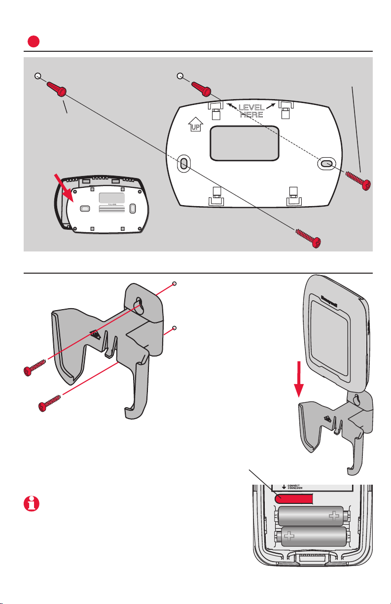
Mount and wire EIM
Mount EIM on wall near HVAC equipment, or on the equipment itself.
Do not install inside HVAC equipment. Use screws & anchors as appropriate
for mounting surface.
EIM wiring
M28467
WIRELESS SETUP
THM5320R
CONNECT
FLASHING: CONNECTING TO REMOTE DEVICE
RED: REMOTE DEVICE(S) NOT COMMUNICATING
GREEN: CONNECTED TO REMOTE DEVICE(S)
CONNECTED
POWER
HEAT
COOL
FAN
M28468
M28469
Install EIM
Install return air sensor (optional)**
The return air sensor maintains safe
indoor temperature (62° F in Heat, 82° F
in Cool) if thermostat power is lost.
Drill 1/4” hole
(6.4mm)
Install sensor on return air duct at least
12” (305mm) upstream from ventilator,
humidifier or dehumidifier (do not mount
downstream)
Strip 1/4” insulation, then insert wires
as shown.
Press tabs only to remove wires from
terminal block if necessary.
Wiring must comply with local
electrical codes.
Continued on next page >>
** For hydronic applications, use
C7189U1005 Remote Indoor Sensor and
mount in the living space.

RedLINK
TM
Installation Guide (EIM)
69-2091EFS—07 4
EIM wiring guide
See detailed wiring guides for specific system
types on pages 16-17.
FURNACE
Transformer
24Vac
120Vac
Stage 1 heat
Air Conditioning
Compressor
(Stage 1)
Compressor
(Stage 2)
Return air sensor**
M28470
Stage 2 heat
Fan
Jumper
A/B/C/D UNUSED
(reserved for future use)
EQUIPMENT INTERFACE MODULE
** or C7189U1005 Remote indoor sensor for hydronic
AIR HANDLER
Transformer
24Vac
Changeover
relay
Backup heat
(gas/electric)
Compressor
(Stage 1)
Compressor
(Stage 2)
Fan Relay
M28471
Relay **
Return
Air Sensor
120Vac
Jumper
A/B/C/D UNUSED
(reserved for future use)
** L terminal sends continuous output when thermostat is
set to EmHeat. L terminal is for use with zone panels.
EQUIPMENT INTERFACE MODULE
CONVENTIONAL SYSTEMS
HEAT PUMP SYSTEMS
Français : voir la page 21 • Español: vea la página 41
5 69-2091EFS—07
M28474
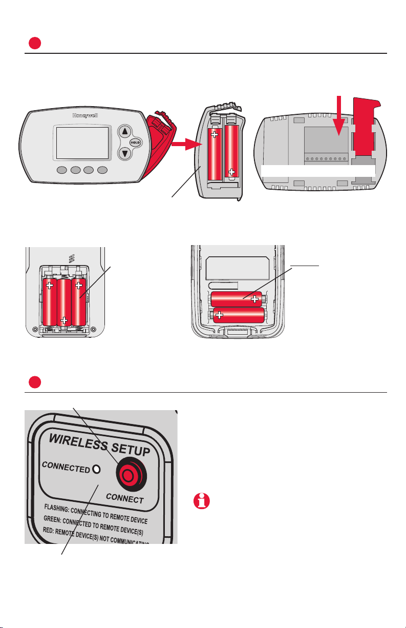
2
Install batteries in wireless devices
When system wiring is complete, install batteries in all devices. Make sure
batteries are inserted properly (see polarity marks on illustrations below).
3
Link all devices to wireless network
M28472
M28473
M28475
M28476
M28495
Thermostat
Remote control (optional) Outdoor air sensor (optional)
Restore AC power, then press and release
the CONNECT button at the EIM. Wait for
green flashing light to begin linking devic-
es to the wireless network (see pages 6-7).
If the light stops flashing before you have
linked all devices, press CONNECT again.
If light does not flash, another EIM/
wireless adapter may be in wireless setup
mode. Exit wireless setup at the other
EIM/wireless adapter.
Continued on next page >>
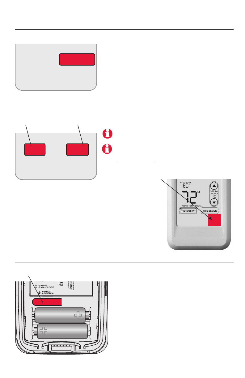
Install 2 fresh AA
batteries
Install quick reference
card
Programmable models only
Install 3 fresh AA
batteries
Install 2 fresh AA
lithium batteries
Press and release CONNECT
Flashing status light times out after 15
minutes of inactivity. Press CONNECT
again if necessary.
RedLINK
TM
Installation Guide (EIM)
69-2091EFS—07 6
M28477
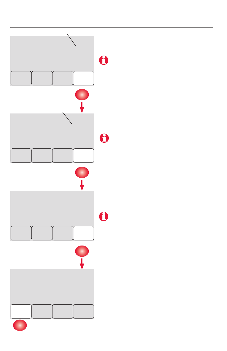
0
0
Wireless Setup
Next
M28478
36
52
Wireless Setup
Next
Back
M28479
Wireless Setup
Connect
Back
M28480
Wireless Setup
Connected
Done
Link thermostat to wireless network
Zone number
Zone name
Press NEXT (always leave zone number set
to zero).
Zone numbers 1-4 are for use with
TrueZONE panels only.
Press NEXT (or see page 11 to change the
zone name if needed).
Change zone name only if you have more
than one thermostat and EIM.
Press CONNECT to establish a link to the wire-
less network.
If E1 appears, see error codes on page 14.
After a brief pause, the confirmation screen
at left should be displayed, to verify that the
wireless connection has been established.
Press DONE to display the home screen.
Français : voir la page 21 • Español: vea la página 41
7 69-2091EFS—07
Link remote control to wireless network (optional)
Link outdoor sensor to wireless network (optional)
CONNECT
WIRELESS SETUP
M28481
M28483
NOYES
CONNECT MORE?
M28482
1 Make sure the Connected light on the
EIM is flashing (see page 5).
2 Press CONNECT at the remote. There will
be a short delay as the remote seeks a
signal from the wireless network.
3 When the screen displays "Connected,"
press DONE.
4 Press NO at the next screen to save and
exit. (Or press YES and repeat steps 1-4
to link another EIM.)
1 Make sure the Connected light on the
EIM is flashing (see page 5).
2 Press and release the CONNECT button
on the back of the sensor.
3 Check thermostat to verify that the
outdoor sensor is working. After about
15 seconds, the thermostat should
display outdoor temperature and
humidity.
Press to link
another EIM
Press to save
and exit
If E1 appears, see error codes on page 14.
The linking procedure may time out if there is
no keypress within 30 minutes. To begin again,
press and hold the blank space (or arrow, if
present) in the lower right corner of the screen
until the display changes (about 3 seconds).
Press and release
(If you are installing more than one EIM,
repeat steps 1-3 for each.)
RedLINK
TM
Installation Guide (EIM)
69-2091EFS—07 8
4
Exit wireless setup
5
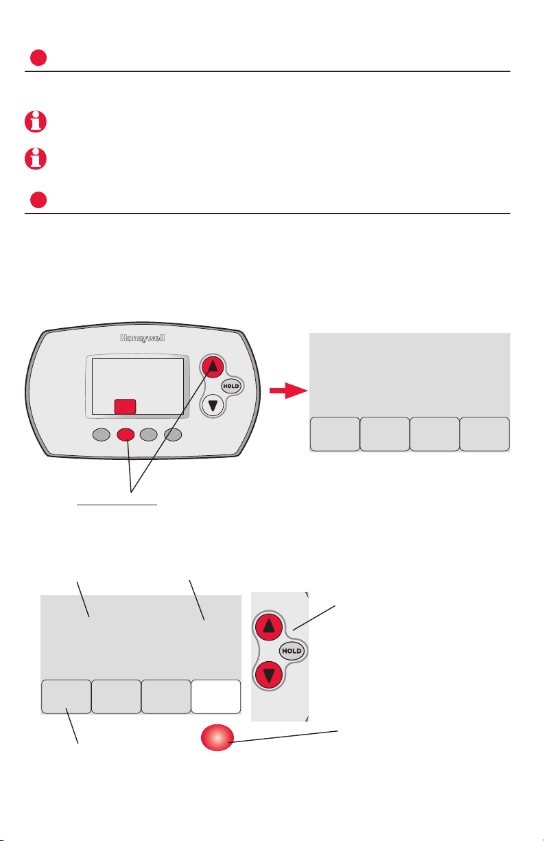
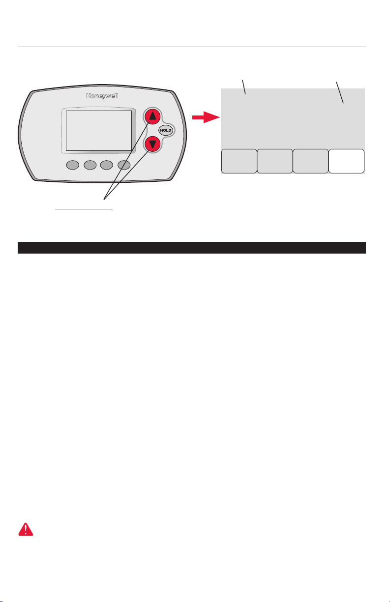
Customize thermostat (installer setup)
Press CONNECT at the EIM to exit wireless setup (light should stop flashing).
Follow the steps below to begin installer setup. At each function screen, press
s or t to change the setting as desired, then press NEXT to advance to the
next function screen.
See tables on pages 9-11 for a description of options for each function.
Press s or t to change
setting (see tables on pages
9-11).
Press NEXT to display next
function screen.
Note: The EIM will automatically exit wireless setup after 15 minutes of inactivity.
Note: If installing more than one thermostat and EIM, you must exit wireless setup
before installing an additional thermostat and EIM.
FAN
M28485
To begin, press and hold the FAN and s buttons
until the display changes (about 3 seconds).
Function
Press DONE to save & exit.
Setting
M28486
0
0
Next
Back
Done
M28487
1
0
Next
Back
Done

Français : voir la page 21 • Español: vea la página 41
9 69-2091EFS—07
Installer setup tables
Setup function Settings & options (factory default in bold)
0 Zone number 0 No zoning (single thermostat used with THM5320R EIM)
[Options: select zone 1, 2, 3 or 4]
1 System type 0 1 heat/1 cool conventional
1 1 heat/1 cool heat pump (no aux. heat)
2 Heat only (includes Series 20)
3 Heat only with fan
4 Cool only
5 2 heat/1 cool heat pump
6 2 heat/2 cool conventional
7 2 heat/1 cool conventional
8 1 heat/2 cool conventional
9 2 heat/2 cool heat pump
10 3 heat/2 cool heat pump
2 Changeover valve
(O/B terminal)
0 O/B terminal controls valve in cooling
1 O/B terminal controls valve in heating
3 Fan control
(conventional heat)
0 Gas/Oil heat (equipment controls fan)
1 Electric furnace (thermostat controls fan)
4 Backup heat (Aux &
EmHeat)
1 Electric backup heat
0 Fossil fuel backup heat
5 Stage 1 heat cycle
rate (CPH: cycles/
hour)
5 Gas or oil furnaces (less than 90% efficiency)
1 Steam or gravity systems
3 Hot water systems & furnaces of over 90% efficiency
9 Electric furnaces
[Cycle rate options: 1 to 12 CPH]
6 Stage 2 heat cycle
rate (CPH)
5 Gas or oil furnaces (less than 90% efficiency)
1 Steam or gravity systems
3 Hot water systems & furnaces of over 90% efficiency
9 Electric furnaces
[Cycle rate options: 1 to 12 CPH]
7 Stage 3 heat cycle
rate (CPH)
5 Gas or oil furnaces (less than 90% efficiency)
1 Steam or gravity systems
3 Hot water systems & furnaces of over 90% efficiency
9 Electric furnaces
[Cycle rate options: 1 to 12 CPH]
8 Emergency heat cycle
rate (CPH)
9 Electric furnace
[Cycle rate options: 1 to 12 CPH]
9 Stage 1 compressor
cycle rate
3 Recommended cycle rate
[Cycle rate options: 1 to 6 CPH]
10 Stage 2 compressor
cycle rate
3 Recommended cycle rate
[Cycle rate options: 1 to 6 CPH]
11 Heat pump type 0 Air to Air Heat Pump
1 Geothermal heat pump
12 Manual/Auto
changeover
0 Manual (User options: Heat/Cool/Off)
1 Automatic (User options: Heat/Cool/Auto/Off)
13 Adaptive Intelligent
Recovery™
Applies only to Model TH6320
1 On
0 Off
14 Temperature
display
0 Fahrenheit
1 Celsius

RedLINK
TM
Installation Guide (EIM)
69-2091EFS—07 10
15 Compressor off time
(minimum)
5 5 minutes (Heat On/Cool On flashes during off time)
[Options: 0 to 4 minutes]
16 Schedule format Applies only to Model TH6320
0 Weekday/weekend program schedule
1 Weekday/Saturday/Sunday program schedule
17 External fossil fuel kit 1 External fossil fuel kit controls backup heat
0 Thermostat controls backup heat (outdoor sensor required)
18 Dual fuel heat pump
control
1 Droop control**
0 No droop control**
2 Droop control with Aux Heat Lockout**
20 Droop temperature
(dual fuel)
2 Auto temperature droop 2° F (1° C)
[Options: 2 to 5 (2 to 5° F / 1 to 2.5° C)]
21 Dual fuel upstage to
furnace timer
1 1 hour**
[Options: 0 (off) to 16 hours]
22 Outdoor air sensor? 0 No
1 Yes
24 Heat pump
compressor lockout
(balance point)
0 No heat pump compressor lockout**
1 5° F (-15° C) 7 35° F (1.5° C)
2 10° F (-12° C) 8 40° F (4.5° C)
3 15° F (-9.5° C) 9 45° F (7° C)
4 20° F (-6.5° C) 10 50° F (10° C)
5 25° F (-4° C) 11 55° F (13° C)
6 30° F (-1° C) 12 60° F (15.5° C)
25 Heat pump
auxiliary lockout
0 No heat pump auxiliary lockout**
1 5° F (-15° C) 8 40° F (4.5° C)
2 10° F (-12° C) 9 45° F (7° C)
3 15° F (-9.5° C) 10 50° F (10° C)
4 20° F (-6.5° C) 11 55° F (13° C)
5 25° F (-4° C) 12 60° F (15.5° C)
6 30° F (-1° C) 13 65° F (18.5° C)
7 35° F (1.5° C)
26 Auxiliary heat control Applies only to Model TH5320
0 Comfort**
1 Economy
27 Maximum heat
setpoint
90 Max. heat temperature setting is 90° F (32° C)
[Options: 40 °F to 90 °F (4.5 °C to 32 °C)]
28 Minimum cool
setpoint
50 Min. cool temperature setting is 50° F (10° C)
[Options: 50 °F to 99 °F (10 °C to 37 °C)]
32 Temp. display offset
(indoor)
0 Thermostat displays actual temperature
[Options: -3 to +3 °F offset (-1.5 to +1.5 °C)]
33 Temp. display offset
(outdoor)
0 Thermostat displays actual temperature
[Options: -5 to +5 °F offset (-2.5 to +2.5 °C)]
35 Humidity display
offset (outdoor)
3 Thermostat displays actual humidity
[Other options: 0 = -15%, 1 = -10%, 2 = -5%, 4 = +5%, 5 = +10%,
6 = +15% offset]
Setup function Settings & options (factory default in bold)
** See page 11
Installer setup tables
Français : voir la page 21 • Español: vea la página 41
11 69-2091EFS—07
Setup function Settings & options (factory default in bold)
36 Zone name 52 Thermostat
1 Basement 16 Exercise Room 30 Library 44 Porch
2 Bathroom 17 Family Room 31 Living Room 45 Rec Room
3 Bathroom 1 18 Fireplace 32 Lower Level 46 Sewing Room
4 Bathroom 2 19 Foyer 33 Master Bath 47 Spa
5 Bathroom 3 20 Game Room 34 Master Bed 48 Storage Room
6 Bedroom 21 Garage 35 Media Room 49 Studio
7 Bedroom 1 22 Great Room 36 Music Room 50 Sun Room
8 Bedroom 2 23 Guest Room 37 Nursery 51 Theater
9 Bedroom 3 24 Gym 38 Office 52 Thermostat
10 Bedroom 4 25 Kid's Room 39 Office 1 53 Upper Level
11 Boat House 26 Kitchen 40 Office 2 54 Utility Room
12 Bonus Room 27 Kitchen 1 41 Pantry 55 Walk In Closet
13 Computer Room 28 Kitchen 2 42 Play Room 56 Wine Cellar
14 Den 29 Laundry Room 43 Pool Room 57 Workshop
15 Dining Room
39 Wireless setup 0 Disconnect thermostat from wireless system
1 Thermostat is connected to wireless system
90 RESET 0 No reset
1 Reset installer options & program schedule to factory default settings
Special functions
Comfort/Economy — Setup Function 26 (Not available when Setup Function 17 is set to 0):
If you choose Comfort, auxiliary heat will respond quickly to meet the temperature setpoint. If you
choose Economy, the system will wait longer. Auxiliary heat will be activated only if the setpoint is
not reached within a reasonable time.
Heat Pump Control — Fossil Fuel Backup (Setup Function 18):
Note: If temperature is not reached in a reasonable time, set the upstage to furnace timer
(function 21). After the designated time, the compressor will turn off and the system will switch to
back up heat.
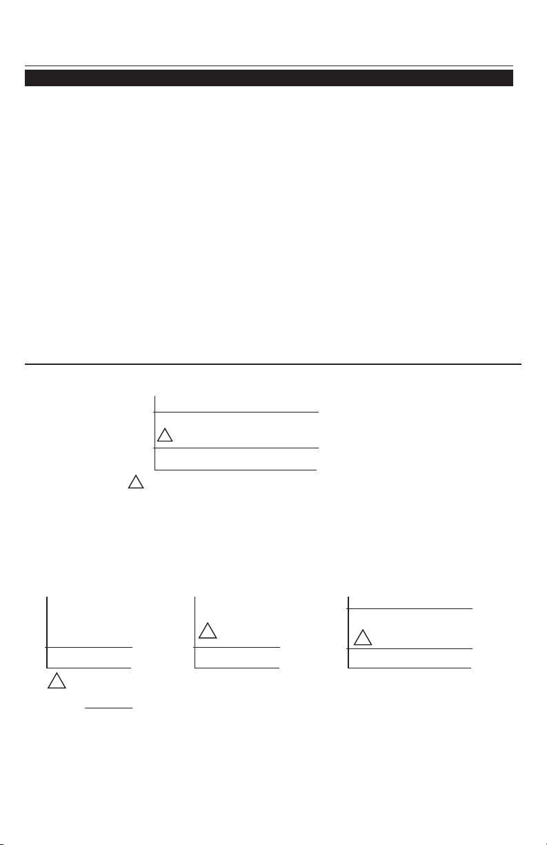
Heat Pump Control — Electric Backup (Setup Functions 24-25):
Installer setup tables
40
55
M28705
COMPRESSOR LOCKOUT
AUXILIARY LOCKOUT
COMPRESSOR AND FAN ONLY
COMPRESSOR AND FAN OPERATE
ELECTRIC BACKUP HEAT AND FAN ONLY
OUTDOOR TEMP.
IF THE COMPRESSOR CANNOT REACH OR MAINTAIN TEMPERATURE SETTING,
BOTH THE COMPRESSOR AND ELECTRIC BACKUP HEAT WILL OPERATE.
1
1
M28706
IF ROOM TEMPERATURE DROPS (EXCEEDS DROOP SETTING AT FUNCTION 20), COMPRESSOR IS DEACTIVATED. FOSSIL FUEL
BACKUP HEAT IS ACTIVATED AFTER 3 MINUTE DELAY.
1
FOR GEOTHERMAL HEAT PUMPS, THE BALANCE POINT CAN BE DISABLED AT SETUP FUNCTION 24.
**
OPTION 0: NO DROOP CONTROL
40
BALANCE
POINT **
COMPRESSOR AND
FAN ONLY
FOSSIL FUEL
BACKUP HEAT ONLY
OUTDOOR TEMP.
OPTION 1: DROOP CONTROL
OUTDOOR TEMP.
40
BALANCE
POINT **
COMPRESSOR AND
FAN OPERATE
FOSSIL FUEL
BACKUP HEAT ONLY
1
OPTION 2: DROOP CONTROL WITH AUX HEAT LOCKOUT
COMPRESSOR AND FAN OPERATE
OUTDOOR TEMP.
40
55
BALANCE
POINT **
AUXILIARY
LOCKOUT
COMPRESSOR AND FAN ONLY
FOSSIL FUEL BACKUP HEAT ONLY
1
RedLINK
TM
Installation Guide (EIM)
69-2091EFS—07 12
System test
Follow the procedure below to test for proper operation.
M28488
To begin, press and hold the s and t buttons
until the display changes (about 3 seconds).
Press s or t to check system status
Press NEXT to advance to next test
Press DONE to terminate system test
M28489
02
0
Next
Back
Done
System test number System status
System test System status
02 Wireless test
0 Off
1 Test radio signal (after a brief pause, screen displays 1-10 to show
signal strength; 5 or higher recommended)
04 Return air sensor
Screen displays return air temperature if device is installed and
working properly
10 Heating system
0 Heat and fan turn off.
1 Heat turns on
2 Stage 2 heat turns on
3 Stage 3 heat turns on
20 Emergency heating
system
0 Heat and fan turn off
1 Heat and fan turn on
30 Cooling system
0 Compressor and fan turn off
1 Compressor and fan turn on
2 Stage 2 compressor turns on
40 Fan system
0 Fan turns off
1 Fan turns on
70 Thermostat information
(for reference only)
71 Software revision number (major revisions)
72 Software revision number (minor revisions)
73 Configuration identification code (major)
74 Configuration identification code (minor)
75 Production configuration date code (week)
76 Production configuration date code (year)
CAUTION: EQUIPMENT DAMAGE HAZARD. Compressor protection (minimum
off time) is bypassed during testing. To prevent equipment damage, avoid cycling
the compressor quickly.
Français : voir la page 21 • Español: vea la página 41
13 69-2091EFS—07
Outdoor sensor (optional)
6
Mount thermostat & outdoor sensor
M28490
3/16" holes for drywall
7/32" holes for plaster
Wall anchor
Detach wallplate
Mounting screw
Wallplate
M28483
M28491
M28492
Mount the sensor on
a vertical exterior wall,
at least 6 inches below
any overhang. Choose a
location protected from
direct sunlight.
Place sensor securely
in bracket, facing
away from wall.
Press and release
To check location before mounting: Restore
thermostat Home screen, then hold the sensor
where you intend to install it and press the
CONNECT button. If sensor is working properly,
thermostat will switch to display outdoor
temperature and humidity.
RedLINK
TM
Installation Guide (EIM)
69-2091EFS—07 14
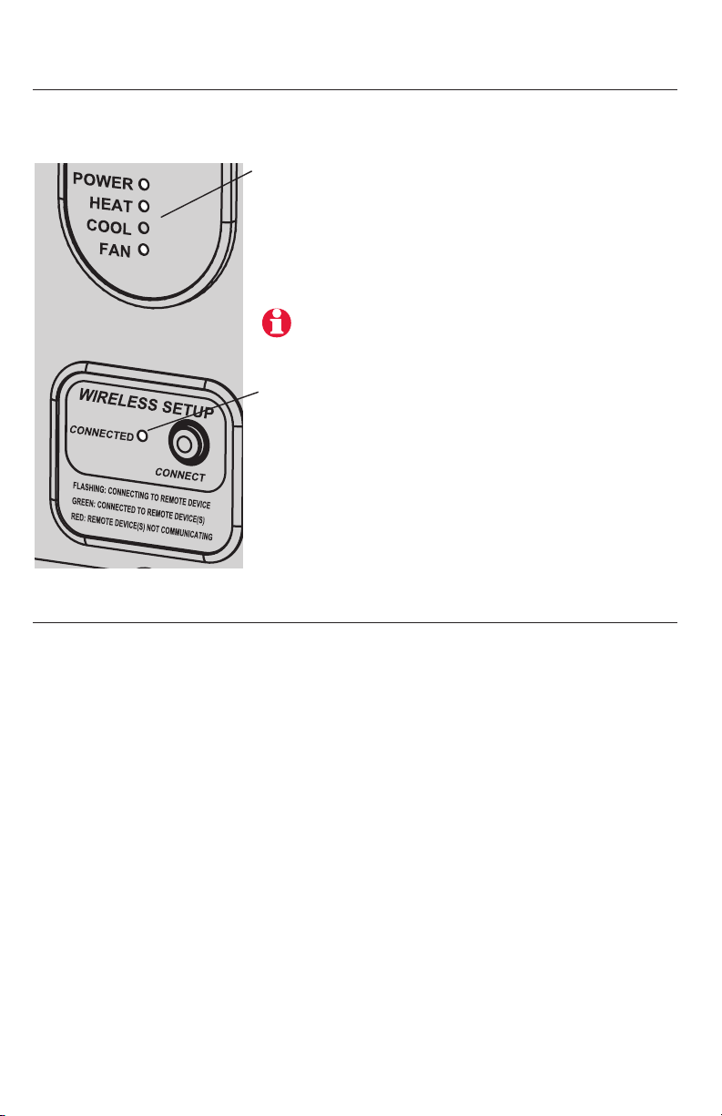
EIM status lights
Error codes (thermostat & remote control)
When installation is complete, check the status lights on the equipment
interface module to verify proper operation.
M28496
System status lights
• Power: EIM is working properly.
• Heat: Heating system is on.
• Cool: Cooling system is on.
• Fan: Fan is on.
Wireless status lights
• Solid green: EIM is working properly
and communicating with wireless
devices
• Flashing green: Linking to wireless
devices (light flashes for 15 minutes
after you press CONNECT).
• Solid red: Communication problem.
Check EIM and wireless devices.
Note: If connected light is flashing, press
CONNECT button to turn off flashing light, then
recheck status lights.
If E1 or E appears, check error code number (right side of screen):
23 EIM does not have dual fuel capability. Replace EIM if you have fossil fuel
backup heat or change Installer Setup Function 4 to ELECTRIC if you have
electric backup heat (see pages 8-10).
29 Attempting to connect incompatible wireless devices.
30 Invalid zone number. Zone number must be set to zero (see page 6).
33 Check Return Air Sensor wiring. If removing the sensor permanently, press and
hold the CONNECT button on the EIM for 10 seconds (until flashing orange) to clear
this error code. See page 15, then pages 5-8 to reconnect wireless devices.
34 Low signal strength. Move wireless device to a different location and try again.
38 Make sure Connected light on EIM is flashing and you are 2+ feet away from EIM.
53 Thermostat is not receiving Outdoor Temperature and Outdoor Humidity:
1. Thermostat may be configured for dual fuel, compressor lockout or auxiliary
lockout with no outdoor sensor. Follow Wireless Setup procedure to connect
outdoor sensor to the EIM (see pages 5 and 7).
2. If E53 continues, outdoor sensor may not be communicating. Install 2 fresh AA
Lithium batteries in the outdoor sensor.
Français : voir la page 21 • Español: vea la página 41
15 69-2091EFS—07
Replacing system components
Thermostat
To replace a thermostat, install batteries and follow the procedures on pages 5-6
to link it to the wireless network. If necessary, modify settings as needed (see
tables on pages 9-11).
Remote control & outdoor sensor
To replace a remote control or outdoor air sensor, install batteries and follow the
procedures on pages 5-7 to link it to the wireless network.
Equipment interface module (EIM)
After installing a new EIM, you must re-set the thermostat and remote control to
communicate with the new EIM, as described below.
At the thermostat:
1 Press and hold the FAN and s buttons for 3 seconds.
2 Press BACK twice to display Function 39 (wireless setup).
3 Press t to change Function 39 setting to 0 (disconnect from old EIM).
4 Follow the procedures on pages 5-6 to link to new EIM.
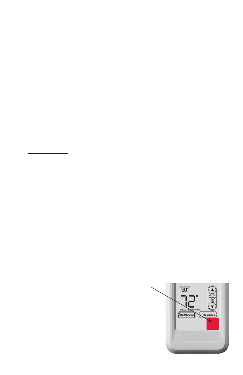
At the remote control:
1 Press and hold the blank space (or arrow if present) in the lower right
corner of the screen until the display changes (about 3 seconds).
2 Press REMOVE, then YES to disconnect from old EIM.
3 Follow the procedure on page 7 to link to new EIM.
Press and hold for
about 3 seconds.
RedLINK
TM
Installation Guide (EIM)
69-2091EFS—07 16
System-specific wiring guides
Conventional systems
See [notes] on next page.
1H/1C System (1 transformer)
C 24VAC common
R Power [1]
Rc [R+Rc+Rh joined by jumper]
Rh [R+Rc+Rh joined by jumper]
W Heat relay
Y Compressor contactor
G Fan relay
Heat-only System [3]
C 24VAC common
R Power [1]
Rc [R+Rc+Rh joined by jumper]
Rh [R+Rc+Rh joined by jumper]
W Heat relay
Heat-only System (Series 20) [3]
C 24VAC common
R Series 20 valve terminal "R" [1]
Rc [R+Rc+Rh joined by jumper]
Rh [R+Rc+Rh joined by jumper]
W Series 20 valve terminal "B"
Y Series 20 valve terminal “W”
Heat-only System
(normally open zone valve) [3]
C 24VAC common
R Power [1]
Rc [R+Rc+Rh joined by jumper]
Rh [R+Rc+Rh joined by jumper]
Y Normally open zone valve
Heat Only System With Fan [4]
C 24VAC common
R Power [1]
Rc [R+Rc+Rh joined by jumper]
Rh [R+Rc+Rh joined by jumper]
W Heat relay
G Fan relay
Cool Only System [5]
C 24VAC common
R Power [1]
Rc [R+Rc+Rh joined by jumper]
Rh [R+Rc+Rh joined by jumper]
Y Compressor contactor
G Fan relay
1H/1C System (2 transformers)
C 24VAC common
R Power [1]
Rc Power (cooling) [1, 2]
Rh Power (heating) [1, 2]
W Heat relay
Y Compressor contactor
G Fan relay
2H/2C System (1 transformer) [6]
C 24VAC common
R Power [1]
Rc [R+Rc+Rh joined by jumper]
Rh [R+Rc+Rh joined by jumper]
W Heat relay (stage 1)
W2 Heat relay (stage 2)
Y Compressor contactor (stage 1)
Y2 Compressor contactor (stage 2)
G Fan relay
2H/2C System (2 transformers) [6]
C 24VAC common
R Power [1]
Rc Power (cooling) [1, 2]
Rh Power (heating) [1, 2]
W Heat relay (stage 1)
W2 Heat relay (stage 2)
Y Compressor contactor (stage 1)
Y2 Compressor contactor (stage 2)
G Fan relay
Français : voir la page 21 • Español: vea la página 41
17 69-2091EFS—07
System-specific wiring guides
Heat pump systems
See [notes] below.
1H/1C Heat Pump [8]
C 24VAC common
R Power [1]
Rc [R+Rc+Rh joined by jumper]
Rh [R+Rc+Rh joined by jumper]
O/B Changeover valve [7]
Y Compressor contactor
G Fan relay
2H/1C Heat Pump [9]
C 24VAC common
R Power [1]
Rc [R+Rc+Rh joined by jumper]
Rh [R+Rc+Rh joined by jumper]
O/B Changeover valve [7]
Aux Auxiliary heat relay
Y Compressor contactor
G Fan relay
L Relay [12]
2H/2C Heat Pump [10]
C 24VAC common
R Power [1]
Rc [R+Rc+Rh joined by jumper]
Rh [R+Rc+Rh joined by jumper]
O/B Changeover valve [7]
Y Compressor contactor (stage 1)
Y2 Compressor contactor (stage 2)
G Fan relay
3H/2C Heat Pump [11]
C 24VAC common
R Power [1]
Rc [R+Rc+Rh joined by jumper]
Rh [R+Rc+Rh joined by jumper]
O/B Changeover valve [7]
Aux Auxiliary heat relay
Y Compressor contactor (stage 1)
Y2 Compressor contactor (stage 2)
G Fan relay
L Relay [12]
[1] Power supply. Provide disconnect means and overload protection as required.
[2] Remove jumper (Rc to Rh) for systems with two transformers.
[3] In Installer Setup, set system type to Heat Only.
[4] In Installer Setup, set system type to Heat Only with Fan.
[5] In Installer Setup, set system type to Cool Only.
[6] In Installer Setup, set system type to 2 Heat/2 Cool Conventional.
[7] In Installer Setup, set changeover valve to O or B.
[8] In Installer Setup, set system type to 1 Heat/1 Cool Heat Pump.
[9] In Installer Setup, set system type to 2 Heat/1 Cool Heat Pump.
[10] In Installer Setup, set system type to 2 Heat/2 Cool Heat Pump.
[11] In Installer Setup, set system type to 3 Heat/2 Cool Heat Pump.
[12] “L” terminal sends a continuous output when thermostat is set to Em. Heat. Connect
to zoning panel and switch to Emergency Heat.

RedLINK
TM
Installation Guide (EIM)
69-2091EFS—07 18
Specifications & replacement parts
Operating Ambient Temperature
Thermostat: 32 to 120° F (0 to 48.9° C)
Remote control: 32 to 120° F (0 to 48.9° C)
EIM: -40 to 165° F (-40 to 73.9° C)
Outdoor air sensor: -40 to 140° F (-40 to 60° C)
Return air sensor: 0 to 200° F (-17.8 to 93.3° C)
Operating Relative Humidity
Thermostat: 5% to 90% (non-condensing)
Remote control: 5% to 90% (non-condensing)
EIM: 5% to 95% (non-condensing)
Outdoor air sensor: 0% to 100% (condensing)
Physical Dimensions (height, width, depth)
Thermostat: 3-9/16 x 5-13/16 x 1-1/2 inches (91 x 147 x 38 mm)
EIM: 8-1/8 x 8 x 1-7/8 inches (206 x 203 x 47 mm)
Outdoor air sensor: 5 x 3-1/2 x 1-11/16 inches (127 x 89 x 43 mm)
Return air sensor: 3-7/8 x 4-1/8 x 1-1/4 inches (77 x 102 x 25 mm)
Sensor probe is 3-3/4 inches long (77 mm)
Terminal Voltage (50/60Hz) Running Current
W (heating) 18-30 VAC 1.00A
Y (cooling) 18-30 VAC 1.00A
G (fan) 18-30 VAC 0.60A
O/B (changeover) 18-30 VAC 0.60A
W2 (heating) 18-30 VAC 0.60A
Y2 (cooling) 18-30 VAC 0.60A
Aux/E (auxiliary) 18-30 VAC 1.00A
L (output) 18-30 VAC 0.60A
Item Part Number
Equipment Interface Module (EIM) THM5320R1000
Wireless adapter THM4000R1000
FocusPRO
®
wireless thermostat (programmable) TH6320R1004
FocusPRO
®
wireless thermostat (non-programmable) TH5320R1002
Remote control REM5000R1001
Outdoor air sensor C7089R1013
Return air sensor (for backup control) C7735A1000
Remote indoor sensor C7189U1005
(alternative sensor for backup control in hydronic applications)
Battery holder 50007072-001
Cover plate (covers marks left by old thermostats) 50002883-001
Electrical Ratings (EIM)
Accessories & Replacement Parts
 Loading...