


SmartVFD HVAC
Honeywell
SmartVFD HVAC
Installation manual
Variable Frequency Drives
for Variable Torque Applications
%\XVLQJWKLV+RQH\ZHOOOLWHUDWXUH\RXDJUHHWKDW+RQH\ZHOOZLOOKDYHQROLDELOLW\
IRUDQ\GDPDJHVDULVLQJRXWRI\RXUXVHRUPRGLILFDWLRQWRWKHOLWHUDWXUH<RXZLOO
GHIHQGDQGLQGHPQLI\+RQH\ZHOOLWVDIILOLDWHVDQGVXEVLGLDULHVIURPDQGDJDLQVW
DQ\OLDELOLW\FRVWRUGDPDJHVLQFOXGLQJDWWRUQH\V¶IHHVDULVLQJRXWRIRUUHVXOWLQJ
IURPDQ\PRGLILFDWLRQWRWKHOLWHUDWXUHE\\RX
38-00007-03

Honeywell • 0
INDEX
Document: DPD00323D
Version release date: 18.1.18
1. Safety ..................................................................................................................2
1.1 Danger ............................................................................................................................ 2
1.2 Warnings......................................................................................................................... 3
1.3 Grounding and ground fault protection ........................................................................... 3
1.4 Running the motor .......................................................................................................... 4
2. Receipt of delivery.............................................................................................5
2.1 ‘Product modified’ sticker ................................................................................................ 5
2.2 Unpacking and lifting the drive........................................................................................ 5
2.2.1 Lifting frames MR8 and MR9 .......................................................................................... 6
2.3 Type designation code.................................................................................................... 7
2.4 Accessories..................................................................................................................... 8
3. Mounting.............................................................................................................9
3.1 Dimensions ..................................................................................................................... 9
3.1.1 Wall mount, MR4-MR7.................................................................................................... 9
3.1.2 Wall mount, MR8 and MR9........................................................................................... 11
3.1.3 Flange mount................................................................................................................ 12
3.2 Cooling.......................................................................................................................... 17
4. Power cabling ..................................................................................................19
4.1 UL standards on cabling ............................................................................................... 20
4.1.1 Cable dimensioning and selection ................................................................................ 20
4.2 Control cables ...............................................................................................................22
4.3 Cable installation...........................................................................................................23
4.3.1 Frames MR4 to MR7..................................................................................................... 23
4.3.2 Frames MR8 and MR9.................................................................................................. 30
4.3.3 Cable and motor insulation checks............................................................................... 38
4.4 Installation in corner-grounded network........................................................................ 38
5. Commissioning................................................................................................39
5.1 Commissioning of the SmartVFD HVAC....................................................................... 40
5.2 Changing EMC protection class.................................................................................... 41
5.2.1 Frames MR4 to MR6..................................................................................................... 41
5.2.2 Frames MR7 and MR8.................................................................................................. 43
5.2.3 Frame MR9 ................................................................................................................... 45
6. Control unit ......................................................................................................47
6.1 Control Unit Cabling...................................................................................................... 48
6.1.1 Selection of the Control Cables .................................................................................... 48
6.1.2 Control Terminals and Dip Switches............................................................................. 48
6.2 Fieldbus Connection ..................................................................................................... 52
6.2.1 Using Fieldbus Through an Ethernet Cable.................................................................. 53
6.2.2 Using Fieldbus Through an RS485 Cable .................................................................... 55
6.3 Installation of Option Boards......................................................................................... 59
6.4 Installation of a Battery for the Real Time Clock (RTC)................................................ 61
6.5 Galvanic Isolation Barriers............................................................................................ 62
7. Maintenance .....................................................................................................63
8. Product data.....................................................................................................64
8.1 Power ratings................................................................................................................64

Honeywell • 1
8.1.1 Mains voltage 208-240 V .............................................................................................. 64
8.1.2 Mains voltage 380-480V ............................................................................................... 65
8.1.3 Mains voltage 525-600V ............................................................................................... 66
8.1.4 Definitions of overloadability ......................................................................................... 67
8.2 SmartVFD HVAC - technical data................................................................................. 68
8.2.1 Technical information on control connections............................................................... 71
SAFETY Honeywell • 2
1
1. SAFETY
This manual contains clearly marked cautions and warnings which are intended for your per-
sonal safety and to avoid any unintentional damage to the product or connected appliances.
Please read the information included in cautions and warnings carefully.
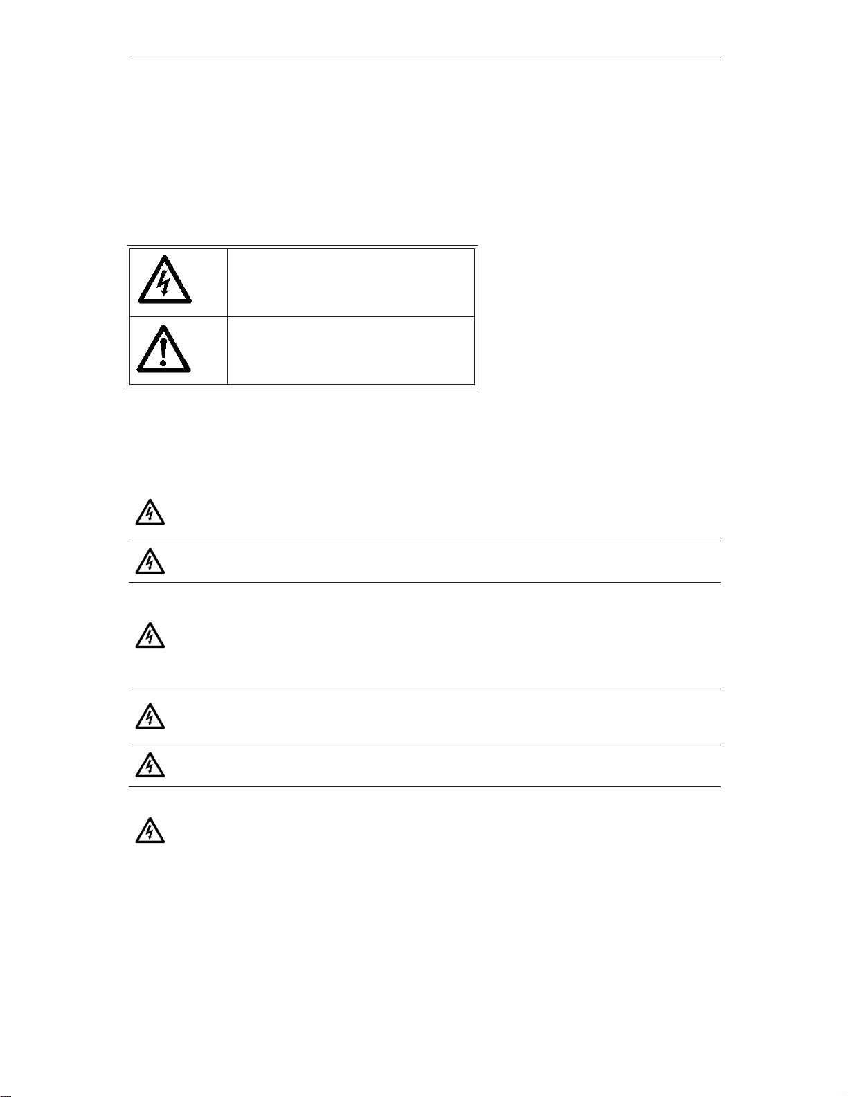
The cautions and warnings are marked as follows:
Table 1. Warning signs
1.1 Danger
= DANGEROUS VOLTAGE!
= WARNING or CAUTION
The components of the power unit of the Smart VFD HVAC are live when the
drive is connected to mains potential. Coming into contact with this voltage is
extremely dangerous and may cause death or severe injury.
The motor terminals U, V, W and the brake resistor terminals are live when
the drive is connected to mains, even if the motor is not running.
After disconnecting the drive from the mains, wait until the indicators on the
keypad go out (if no keypad is attached see the indicators on the cover). Wait 5
more minutes before doing any work on the connections of the drive. Do not open
the cover before this time has expired. After expiration of this time, use a measur-
ing equipment to absolutely ensure that no
voltage is present.
Always ensure
absence of voltage before starting any electrical work!
The control I/O-terminals are isolated from the mains potential. However, the
relay outputs and other I/O-terminals may have a dangerous control voltage
present even when the drive is disconnected from mains.
Before connecting the drive to mains make sure that the front and cable covers
of the drive are closed.
During a ramp stop (see the Application Manual), the motor is still generating
voltage to the drive. Therefore, do not touch the components of the drive before
the motor has completely stopped. Wait until the indicators on the keypad go out
(if no keypad is attached see the indicators on the cover). Wait additional 5 min-
utes before starting any work on the drive.
Honeywell • 3 SAFETY
1.2 Warnings
1.3 Grounding and ground fault protection
The Honeywell Smart VFD HVAC AC drive must always be grounded with an grounding con-
ductor connected to the grounding terminal marked with .
The touch current of the drive exceeds 3.5mA AC. According to EN61800-5-1, one or more of
the following conditions for the associated protective circuit shall be satisfied:
1. A fixed connection and
a) the protective earthing conductor has a cross-sectional area of at least 6 AWG
(10 mm
2
) Cu or 4 AWG (16 mm
2
) Al through its total run.
b) an automatic disconnection of the supply in case of loss of continuity of the protective
conductor. See chapter 4.
The Honeywell Smart VFD HVAC is meant for fixed installations only.
Do not perform any measurements when the drive is connected to the mains.
The touch current of the Honeywell Smart VFD HVAC exceeds 3.5mA AC.
According to standard EN61800-5-1, a reinforced protective ground connec-
tion must be ensured. See chapter 1.3.
If the drive is used as a part of a machine, the machine manufacturer is
responsible for providing the machine with a supply disconnecting device (EN
60204-1).
Only spare parts delivered by Honeywell can be used.
At power-up, power brake, or fault reset the motor will start immediately if the
start signal is active, unless the pulse control for
Start/Stop logic
has been
selected
.
Futhermore, the I/O functionalities (including start inputs) may change if parame-
ters, applications or software are changed.Disconnect, therefore, the motor if an
unexpected start can cause danger.
The motor starts automatically after automatic fault reset if the autoreset func-
tion is activated. See the Application Manual for more detailed information.
Prior to measurements on the motor or the motor cable, disconnect the
motor cable from the drive.
Do not touch the components on the circuit boards. Static voltage discharge
may damage the components.
Check that the EMC level of the drive corresponds to the requirements of your
supply network. See chapter 5.2.
In a domestic environment, this product may cause radio interference in which
case supplementary mitigation measures may be required.
CAUTION!
SAFETY Honeywell • 4
1
c) provision of an additional terminal for a second protective earthing conductor of the
same cross-sectional area as the original protective earthing conductor.
OR
2. Connection with an industrial connector according to IEC 60309 and a minimum protec-
tive earthing connector cross-section of 12 AWG (2.5 mm
2
) as part of a multi-conductor
power cable. Adequate strain relief shall be provided.
NOTE: Due to the high capacitive currents present in the drive, fault current protective switches
may not function properly.
1.4 Running the motor
MOTOR RUN CHECK LIST
NOTE! You can download the English and French product manuals with applicable safety,
warning and caution information from https:// en-US/Pages/de-
fault.aspx.
REMARQUE Vous pouvez télécharger les versions anglaise et française des manuels produit
contenant l’ensemble des informations de sécurité, avertissements et mises en garde applica-
bles sur le site https:// en-US/Pages/default.aspx
.
Do not perform any voltage withstand tests on any part of the drive. There is a
certain procedure according to which the tests shall be performed. Ignoring this
procedure may result in damaged product.
Before starting the motor, check that the motor is mounted properly and
ensure that the machine connected to the motor allows the motor to be started.
Set the maximum motor speed (frequency) according to the motor and the
machine connected to it.
Before reversing the motor make sure that this can be done safely.
Make sure that no power correction capacitors are connected to the motor cable.
Make sure that the motor terminals are not connected to mains potential.

Honeywell • 5 RECEIPT OF DELIVERY
2. RECEIPT OF DELIVERY
Check the correctness of delivery by comparing your order data to the drive information found
on the package label. If the delivery does not correspond to your order, contact the supplier
immediately. See chapter 2.3.
2.1 ‘Product modified’ sticker
In the small plastic bag included with delivery you will find a silver Product modified sticker.
The purpose of the sticker is to notify the service personnel about the modifications made in
the drive. Attach the sticker on the side of the drive to avoid losing it. Should the drive be later
modified mark the change on the sticker.
Figure 1. ‘Product modified’ sticker
2.2 Unpacking and lifting the drive
The weights of the drives vary greatly according to the size. You may need to use a piece of
special lifting equipment to remove the drive from its package. Note the weights of each indi-
vidual frame size in Table 2 below.
Table 2. Frame weights
If you decide to use a piece of lifting equipment see picture below for recommendations to lift
the drive.
Frame Weight [kg] Weight [lb.]
MR4 6.0 13.2
MR5 10.0 22.0
MR6 20.0 44.1
MR7 37.5 82.7
MR8 70.0 154.3
MR9 108.0 238.1
Product modified
Date:
Date:
Date:
9004.emf
RECEIPT OF DELIVERY Honeywell • 6
2
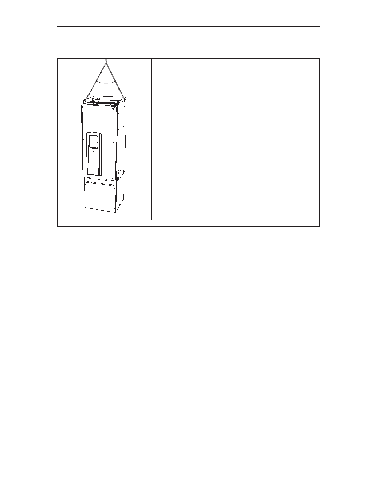
2.2.1 Lifting frames MR8 and MR9
Figure 2. Lifting bigger frames
The Honeywell Smart VFD HVAC undergoes scrupulous tests and quality checks at the factory
before it is delivered to the customer. However, after unpacking the product, check that no
signs of transport damages are to be found on the product and that the delivery is complete.
Should the drive have been damaged during the shipping, please contact primarily the cargo
insurance company or the carrier.
Max. 45°
9012.emf
NOTE: Place the lifting hooks symmetrically in at least two
holes.The lifting device must be able to carry weight of the
drive.
NOTE: The maximum allowed lifting angle is 45 degrees.
Honeywell • 7 RECEIPT OF DELIVERY
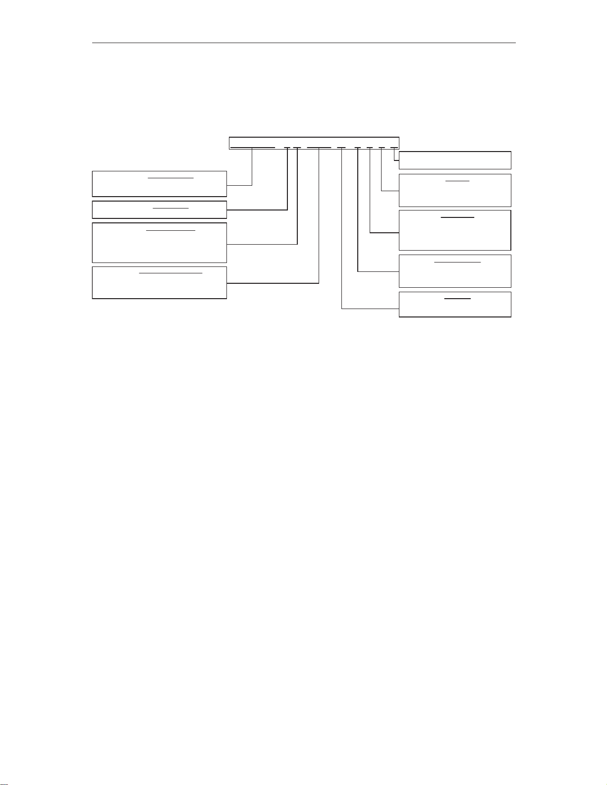
2.3 Type designation code
Honeywell type designation code is formed of a four-segment code. Each segment of the type
designation code uniquely corresponds to the product and options you have ordered. The code
is of the following format:
11447_uk
A = Updated Control Board
No A = Legacy Control Board
T = Text KeyPad
G = Graphic KeyPad
Interface
1 = NEMA 1
2 = NEMA 12
3 = NEMA 3R
Enclosure Type
0 = Drive Only
1 = Disconnect Only
2 = Two Contactor Bypass
3 = Three Contactor Bypass
Contactors
0 = Drive Only or No Special Options
1 = Auto-Bypass
3 = Auto-Bypass and HOA
Options
0007 = .75 Horse Power
0010 = 1 Horse Power
0100 = 10 Horse Power
Nominal Horsepower
A= 208/230 Vac Drive Alone, 208 Vac Bypass
B = 230 Vac Bypass
C = 480 Vac
D = 600 Vac
Nominal Voltage
3 = Three Phase (3~in, 3~out)
Input Phase
HVFDSD = Honeywell SmartVFD HVAC
HVFDSB = Honeywell SmartVFD BYPASS
Product Family
HVFDSD 3 C 0100 G 1 0 0 A

RECEIPT OF DELIVERY Honeywell • 8
2
2.4 Accessories
After having opened the transport package and lifted the converter out, check immediately that
these various accessories were included in the delivery:
• Rubber grommets (sizes vary according to frame)
• Power cable clamps for EMC grounding
• Screws for fixing the power cable clamps
• Control cable grounding clamps
• M4 screw for EMC level change in frame MR7
• Additional grounding screw (if necessary, see chapter 1.3)
• Ferrite holder
• Optional plastic shield to prevent unintended contact with live parts from front (MR8 and
MR9, IP00)
Honeywell • 9 MOUNTING
3. MOUNTING
The drive must be mounted in vertical position on the wall. Ensure that the mounting plane is
relatively even.
The drive shall be fixed with four screws (or bolts, depending on the unit size).
3.1 Dimensions
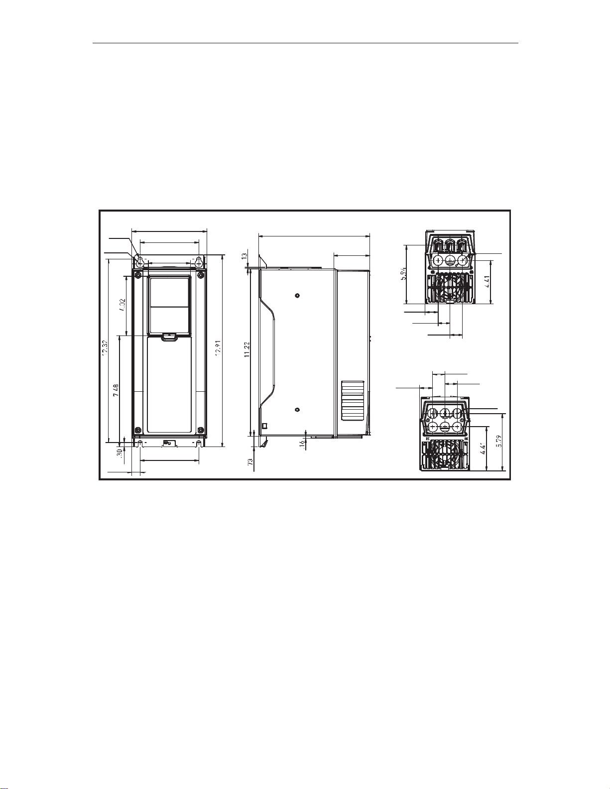
3.1.1 Wall mount, MR4-MR7
Figure 3. SmartVFD HVAC dimensions, MR4, wall mount
5.04
3.94
Ø.28
Ø.51
2.83
.55
3.94
2.44
7.48
NEMA 1
Ø.98
1.30
1.26
1.26
NE MA12
1.26
1.30
1.26
Ø.9 8

MOUNTING Honeywell • 10
3
Figure 4. SmartVFD HVAC dimensions, MR5, wall mount
Figure 5. SmartVFD HVAC dimensions, MR6, wall mount
*Optional mounting holes (for NX replacement)
8.43
5.67
4.53.5 7
Ø.2 8
Ø.5 5
Ø.28
2.83
3.94*
.57 4.53
Ø.2 8
3.94*
NEMA1
1.38 1 .46 1.46
Ø1.30 Ø1.3 0Ø.98
NEMA12
1.36 1.48 1.48
1.38 1.46 1. 46
11449_uk
7.68
5.83
Ø.61
Ø.3 5
2.83
Ø.35
5.83
9.02
2.01 1.83 1.83
NEMA1
Ø1.57Ø1.30Ø1.57
1.42 1.42
2.40
2.01 1.83
NEMA12

Honeywell • 11 MOUNTING
Figure 6. SmartVFD HVAC dimensions, MR7, wall mount
3.1.2 Wall mount, MR8 and MR9
Figure 7. AC drive dimensions, MR8 NEMA1 and NEMA12
10.20
Ø.79
9.33
7.48
Ø.35
Ø.63
Ø2.01
NEMA1
2.72 2.72
1.381.38
NEMA12
Ø.98
Ø1.97
2.72 2.72
1.77 1.77
11451 00
Ø.98
3 x 1.50
Ø2.36
2.46 6.46
11.42
Ø.87
Ø.43
Ø.35
13.50
8.54
Ø.35
Ø.35
26.46
27.32
8.50
37.64
9.25
11452 00
MOUNTING Honeywell • 12
3
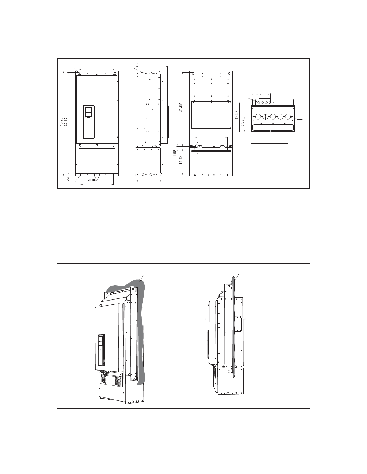
Figure 8. AC drive dimensions, MR9 NEMA1 and NEMA12 (preliminary)
3.1.3 Flange mount
The AC drive can also be recessed into the cabinet wall or similar surface. A special flange
mount option is available for this purpose. For an example of a flange-mounted drive, see Fig-
ure 9.
Figure 9. Example of flange mount (frame MR9)
Ø.35
18.90
15.75
Ø.35
14.17
11.50
Ø.87
14.37
13.98
14.17
Ø.35
Ø.35
11453_00
Cabinet wall
(or similar)
IP21 IP54
Cabinet wall
(or similar)
11454_uk
Honeywell • 13 MOUNTING
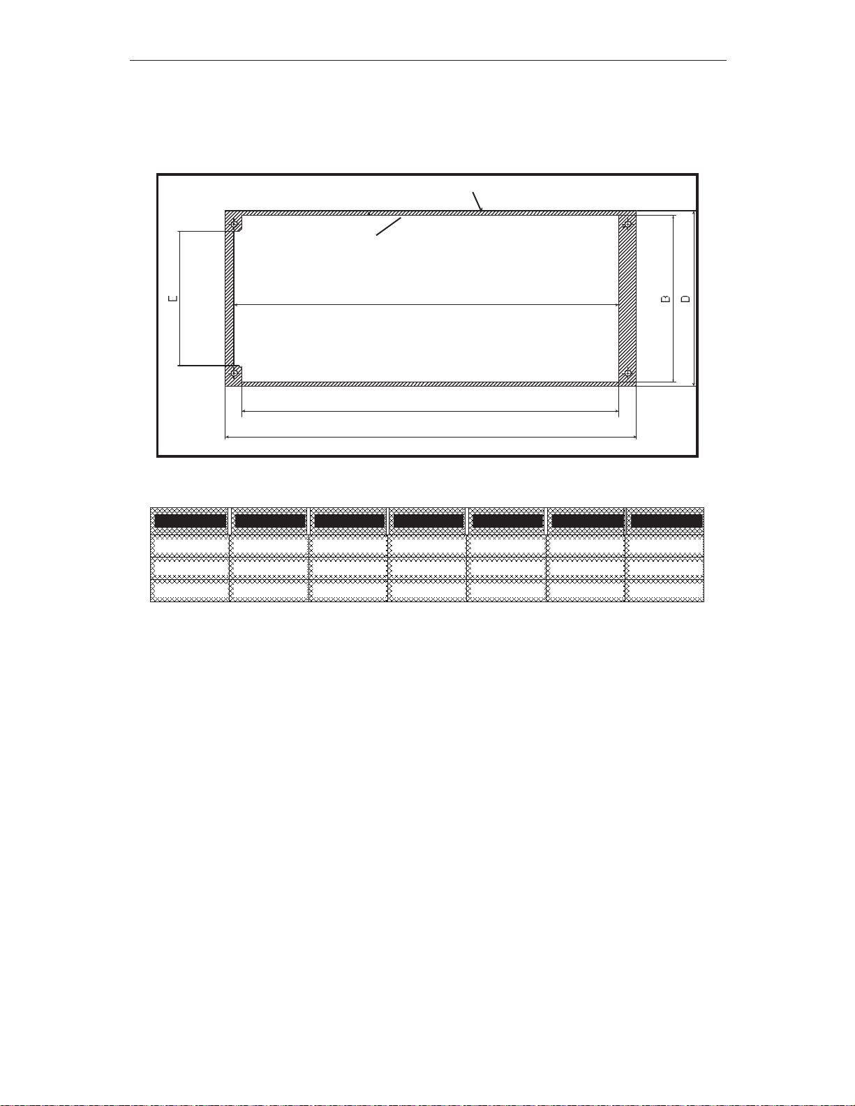
3.1.3.1 Flange mount - Frames MR4 to MR6
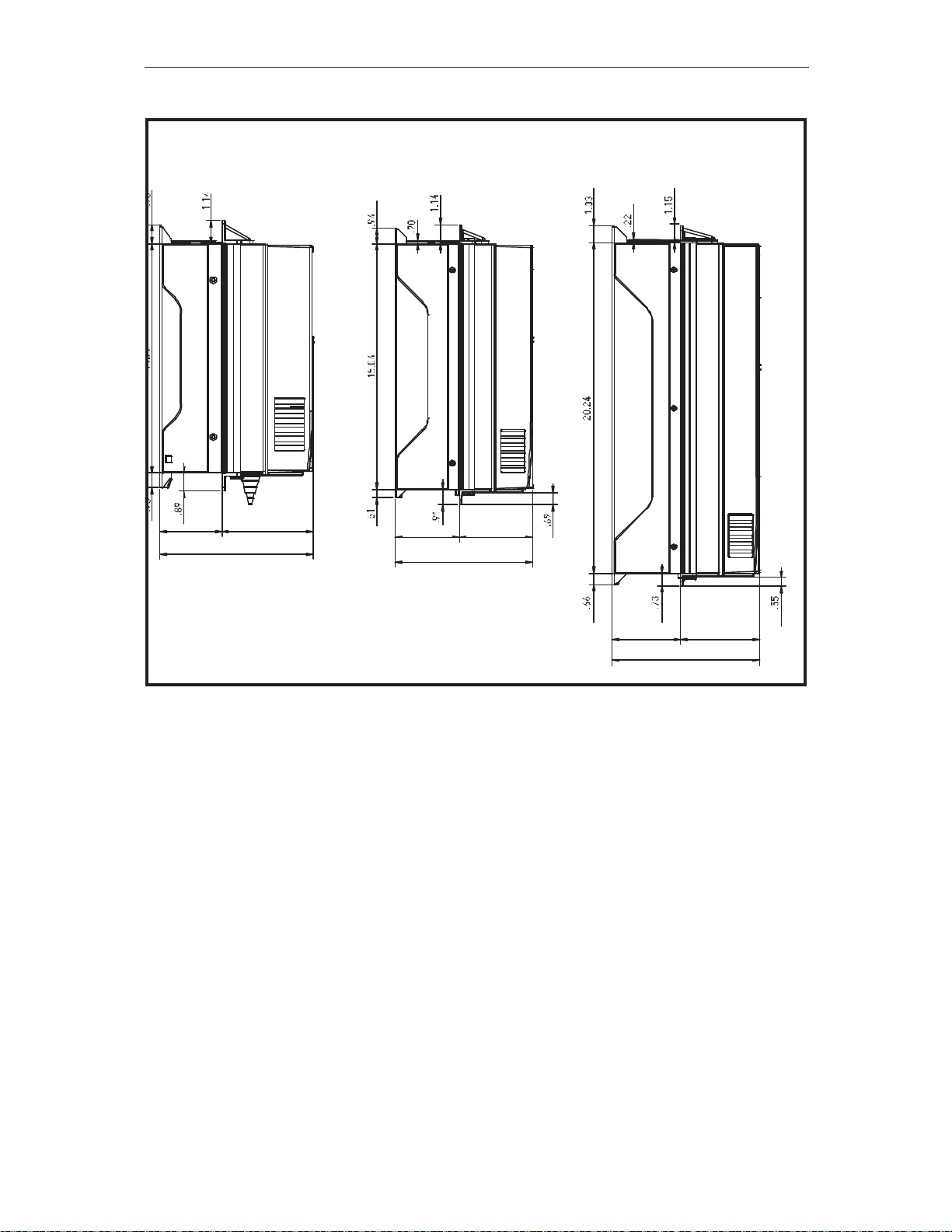
Figure 10. presents the dimensions of the mounting opening and Figure 11. the depth dimen-
sions of the drives with the flange mount option.
Figure 10. Flange mount cutout dimensions for MR4 to MR6
Frame A B C D E F
MR4 12.20 5.39 13.27 5.67 4.33 12.44
MR5 16.06 5.98 17.09 6.30 5.20 16.30
MR6 21.02 7.99 22.05 8.31 7.24 21.30
A
C
F
11455 00
Opening outline
Drive outline
TOP
MOUNTING Honeywell • 14
3
Table 3. Flange mount cutout dimensions for MR4 to MR6 [in]
Figure 11. MR4 to MR6, flange mount, depth dimensions
MR4 MR5 MR6
3.03 4.45
7.48
8.43
4. 49
3.94
4.17 4.84
9.02
Honeywell • 15 MOUNTING
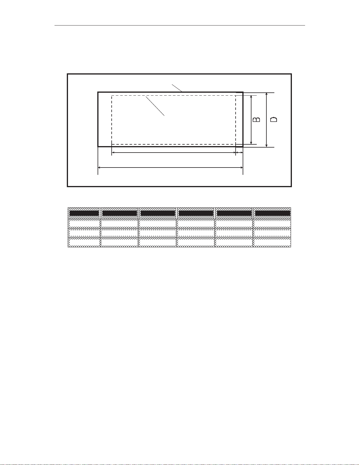
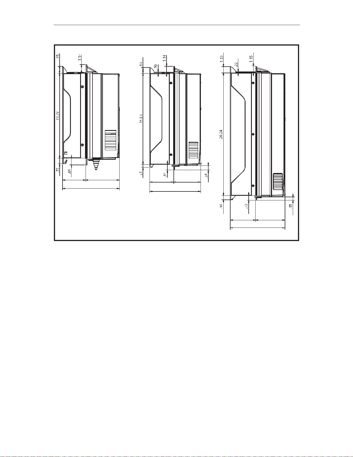
3.1.3.2 Flange mount MR7 to MR9
Figure 12. presents the dimensions of the mounting opening and Figure 13. the dimensions of
the drives with the flange mount option.
Figure 12. Flange mount cutout dimensions for MR7 to MR9
Table 4. Flange mount cutout dimensions for MR7 to MR9 [in]
Frame A B C D E
MR7 25.79 9.45 26.85 10.55 .53
MR8 33.82 11.73 34.96 14.13 .67
MR9 38.39 19.09 41.34 20.87 2.13
C
A E
11482_00
Drive outline
Opening outline
TOP
MOUNTING Honeywell • 16
3
Figure 13. MR7 to MR9, flange mount, depth dimensions
3.03 4.45
7.48
8.43
4. 49
3.94
4.17 4.84
9.02
11456_00
Honeywell • 17 MOUNTING
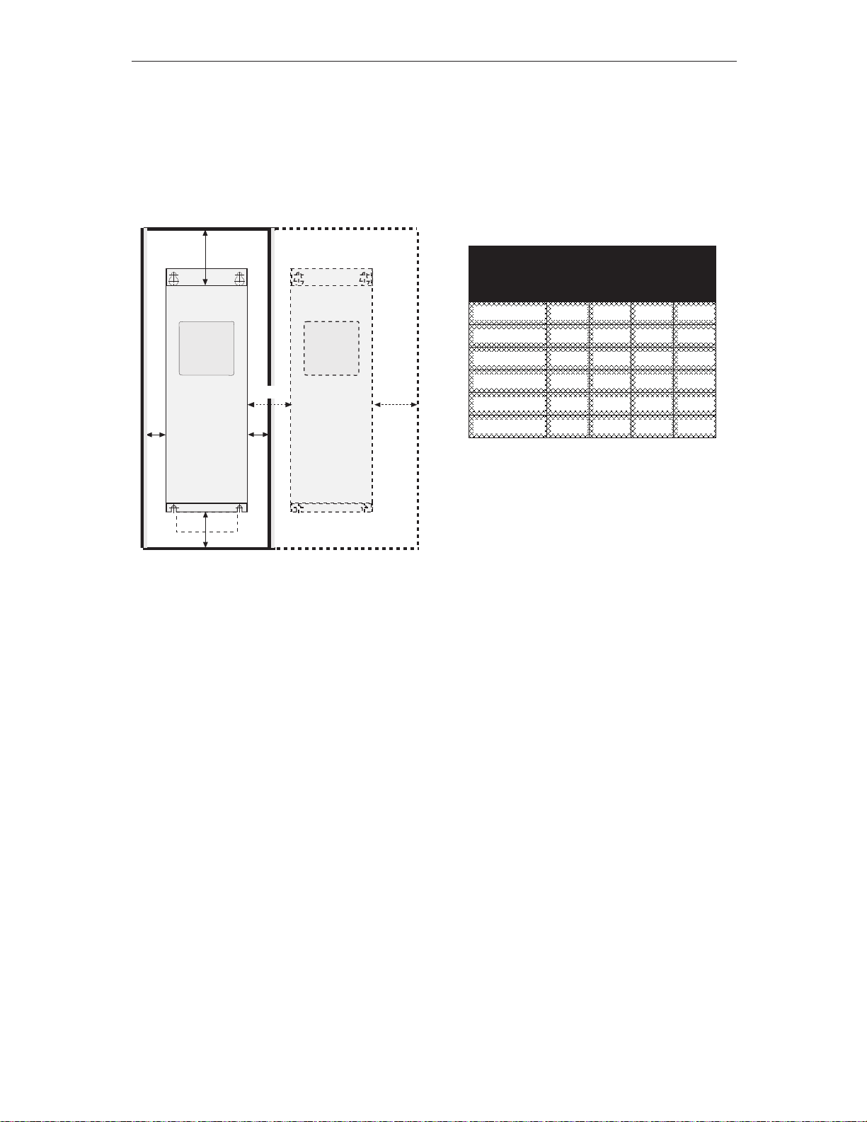
3.2 Cooling
The drive produces heat in operation and is cooled by air circulated by a fan. Enough free
space needs to be left around the drive to ensure sufficient air circulation and cooling. Different
acts of maintenance also require a certain amount of free space.
Make sure that the temperature of the cooling air does not exceed the maximum ambient tem-
perature of the converter.
Table 5. Min. clearances around drive
Figure 14. Installation space
A = clearance around the drive (see also B)
B = distance from one drive to another or distance to cabinet wall
C = free space above the drive
D = free space underneath the drive
Min clearance [in], NEMA1
Type A
*
*. Min clearances A and B for
drives with IP54 enclosure is 0
in.
B
*
C D
MR4 .79 .79 3.94 1.97
MR5 .79 .79 4.72 2.36
MR6 .79 .79 6.30 3.15
MR7 .79 .79 9.84 3.94
MR8 .79 .79 11.8 5.91
MR9 .79 .79 13.78 7.87
C
A
9013.emf
D
B
A
B
MOUNTING Honeywell • 18
3
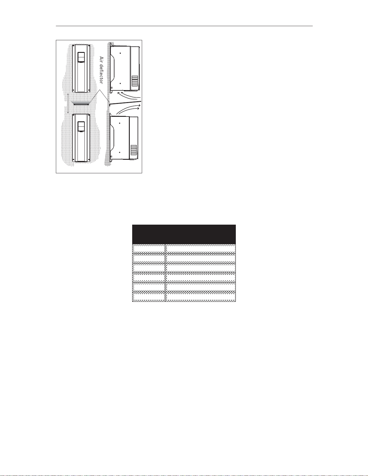
Note that if several units are mounted above one another the
required free space equals C + D (see Figure 15.). Moreover,
the outlet air used for cooling by the lower unit must be direct-
ed away from the air intake of the upper unit.
Figure 15. Installation space when drives are
mounted on top of each other
Table 6. Required cooling air
Type
Cooling air required
[cfm]
MR4 26
MR5 44
MR6 112
MR7 109
MR8 197
MR9 366
C+D
9014.emf
FRONT SIDE
Honeywell • 19 POWER CABLING
4. POWER CABLING
The mains cables are connected to terminals L1, L2 and L3 and the motor cables to terminals
marked with U, V and W. See Table 7 for the cable recommmendations for different EMC lev-
els.
Use cables with heat resistance of at least +158°F. The cables and the fuses must be dimen-
sioned according to the drive nominal OUTPUT current which you can find on the rating plate.
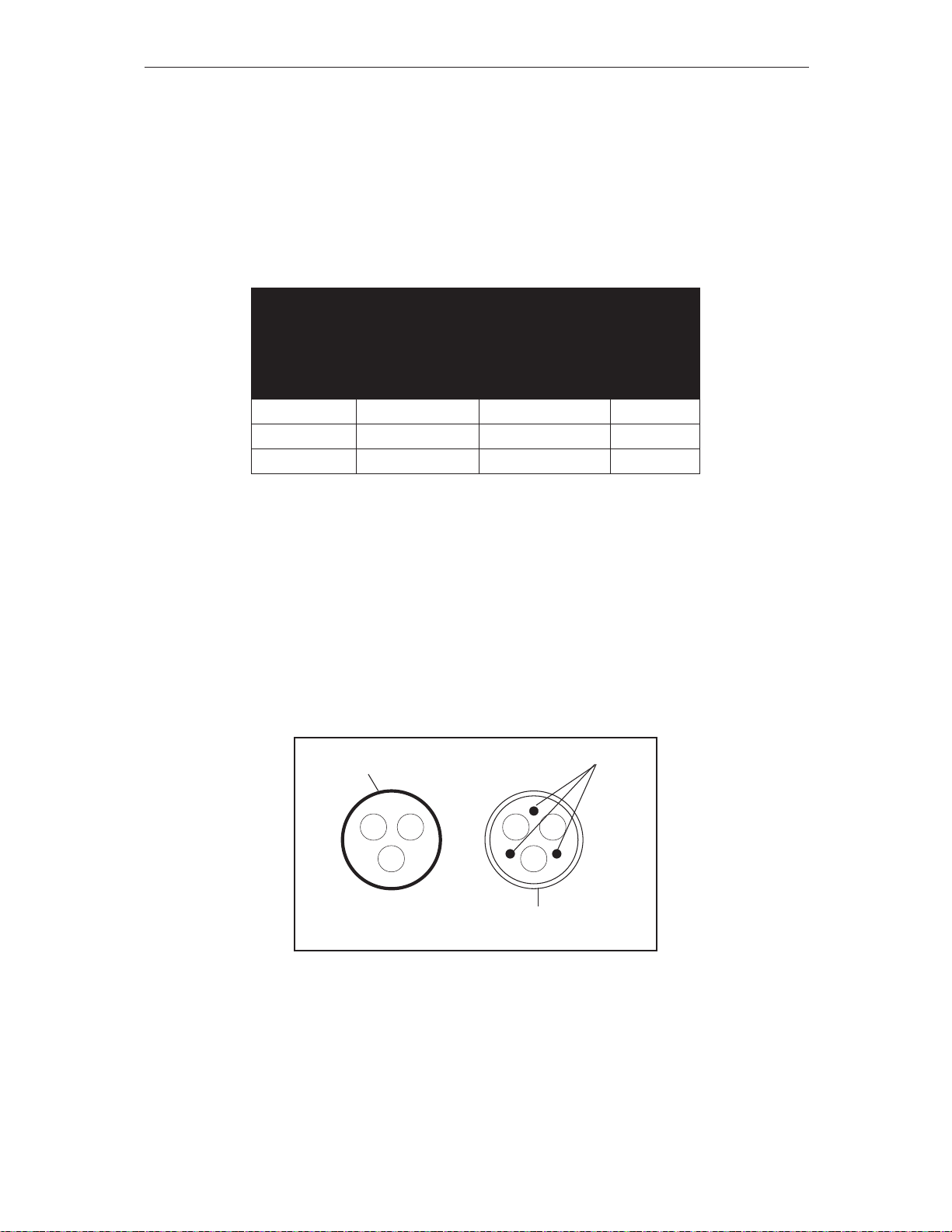
Table 7. Cable types required to meet standards
1 = Power cable intended for fixed installation and the specific mains voltage. Shielded
cable not required. (MCMK or similar recommended).
2 = Symmetrical power cable equipped with concentric protection wire and intended for the
specific mains voltage. (MCMK or similar recommended). See Figure 16.
3 = Symmetrical power cable equipped with compact low-impedance shield and intended
for the specific mains voltage. [MCCMK, EMCMK or similar recommended; Recom-
mended cable transfer impedance (1...30MHz) max. 100mohm/m]. See Figure 16.
*360º grounding of the shield with cable glands in motor end needed for EMC level C2.
4 =Screened cable equipped with compact low-impedance shield (JAMAK, SAB/ÖZCuY-
O or similar).
Figure 16.
NOTE: The EMC requirements are fulfilled at factory defaults of switching frequencies (all
frames).
NOTE: If safety switch is connected the EMC protection shall be continuous over the whole ca-
ble installation.
1
st
environment 2nd environment
Cable type
EMC levels
According to EN61800-3 (2004)
Category C2 Category C3 Level T
Mains cable 1 1 1
Motor cable 3* 2 2
Control cable 4 4 4
9007.emf
PE conductor
and shield
PE conductors
Shield

POWER CABLING Honeywell • 20
4
4.1 UL standards on cabling
To meet the UL (Underwriters Laboratories) regulations, use a UL-approved copper cable with
a minimum heat-resistance of +140/167°F. Use Class 1 wire only.
The units are suitable for use on a circuit capable of delivering not more than 100,000 rms sym-
metrical amperes, 600V maximum.
4.1.1 Cable dimensioning and selection
Table 8 shows the minimum dimensions of the Cu/Al-cables and the corresponding fuse sizes.
Recommended fuse types are gG/gL.
These instructions apply only to cases with one motor and one cable connection from the drive
to the motor. In any other case, ask the factory for more information.
4.1.1.1 Cable and fuse sizes, frames MR4 to MR6, North America
The recommended fuse types are gG/gL (IEC 60269-1) or class T (UL & CSA). The fuse volt-
age rating should be selected according to the supply network. The final selection should be
made according to local regulations, cable installation conditions and cable specification. Big-
ger fuses than what is recommended below shall not be used.
Check that the fuse operating time is less than 0.4 seconds. Operating time depends on used
fuse type and impedance of the supply circuit. Consult the factory about faster fuses. Honey-
well offers recommendations also for high speed J (UL & CSA), aR (UL recognized, IEC 60269-
4) and gS (IEC 60269-4) fuse ranges.
Frame Type
*
I
L
[A]
Fuse
(class T)
[A]
Mains, motor and
ground cable
Cu
Terminal cable size
Main terminal
Ground
terminal
MR4
A007 3.7 6 AWG14 AWG24-AWG10 AWG17-AWG10
A0010 4.8 6 AWG14 AWG24-AWG10 AWG17-AWG10
A0015 6.6 10 AWG14 AWG24-AWG10 AWG17-AWG10
A0020 8 10 AWG14 AWG24-AWG10 AWG17-AWG10
A0030 11 15 AWG14 AWG24-AWG10 AWG17-AWG10
A0040 12.5 20 AWG14 AWG24-AWG10 AWG17-AWG10
C 0015 3.4 6 AWG14 AWG24-AWG10 AWG17-AWG10
C 0020 4.8 6 AWG14 AWG24-AWG10 AWG17-AWG10
C 0030 5.6 10 AWG14 AWG24-AWG10 AWG17-AWG10
C 0040 8.0 10 AWG14 AWG24-AWG10 AWG17-AWG10
C 0050 9.6 15 AWG14 AWG24-AWG10 AWG17-AWG10
C 0075 12.0 20 AWG14 AWG24-AWG10 AWG17-AWG10

Honeywell • 21 POWER CABLING
Table 8. Cable and fuse sizes for Honeywell Smart VFD HVAC (MR4 to MR6)
The cable dimensioning is based on the criteria of the Underwriters’ Laboratories UL508C:Cables must
be PVC-isolated; Max ambient temperature +86°F, max temperature of cable surface +158°F; Use only
cables with concentric copper shield; Max number of parallel cables is 9.
When using cables in parallel,
NOTE HOWEVER that the requirements of both the cross-sectional
area and the max number of cables must be observed.
For important information on the requirements of the grounding conductor, see standard Underwriters’
Laboratories UL508C.
For the correction factors for each temperature, see the instructions of standard Underwriters’ Labora-
tories UL508C.
4.1.1.2 Cable and fuse sizes, frames MR7 to MR9, North America
The recommended fuse types are gG/gL (IEC 60269-1) or class T (UL & CSA). The fuse volt-
age rating should be selected according to the supply network. The final selection should be
made according to local regulations, cable installation conditions and cable specification. Big-
ger fuses than what is recommended below shall not be used.
Check that the fuse operating time is less than 0.4 seconds. Operating time depends on used
fuse type and impedance of the supply circuit. Consult the factory about faster fuses. Honey-
well offers recommendations also for high speed J (UL & CSA), aR (UL recognized, IEC 60269-
4) and gS (IEC 60269-4) fuse ranges.
MR5
A0050 18 25 AWG10 AWG20-AWG5 AWG17-AWG8
A0075 24.2 30 AWG10 AWG20-AWG5 AWG17-AWG8
A0100 31 40 AWG8 AWG20-AWG5 AWG17-AWG8
C 0100 16.0 25 AWG10 AWG20-AWG5 AWG17-AWG8
C 0150 23.0 30 AWG10 AWG20-AWG5 AWG17-AWG8
C 0200 31.0 40 AWG8 AWG20-AWG5 AWG17-AWG8
D0030 3.9 6 AWG14 AWG20-AWG5 AWG17-AWG8
D0050 6.1 10 AWG14 AWG20-AWG5 AWG17-AWG8
D0075 9 10 AWG14 AWG20-AWG5 AWG17-AWG8
D0100 11 15 AWG14 AWG20-AWG5 AWG17-AWG8
MR6
A0150 48 60 AWG4 AWG13-AWG0 AWG13-AWG2
A0200 62 80 AWG4 AWG13-AWG0 AWG13-AWG2
C 0250 38.0 50 AWG4 AWG13-AWG0 AWG13-AWG2
C 0300 46.0 60 AWG4 AWG13-AWG0 AWG13-AWG2
C 0400
**
61.0 80 AWG4 AWG13-AWG0 AWG13-AWG2
D0150 18 20 AWG10 AWG13-AWG0 AWG13-AWG2
D0200 22 25 AWG10 AWG13-AWG0 AWG13-AWG2
D0250 27 30 AWG8 AWG13-AWG0 AWG13-AWG2
D0300 34 40 AWG8 AWG13-AWG0 AWG13-AWG2
*. For more information on type code, see page 7.
**. The 460V models require 90-degree wire to meet UL regulations
Frame Type
*
I
L
[A]
Fuse
(class T)
[A]
Mains, motor and
ground cable
Cu
Terminal cable size
Main terminal
Ground
terminal
 Loading...