


Smart Field
Communicator Model
STS103
Operating Guide
34-ST-11-14F
4/99

Copyright, Notices, and Trademarks
© Copyright 1995 by Honeywell Inc.
Revision F – 4/99
While this information is presented in good faith and believed to be accurate, Honeywell disclaims the implied warranties of merchantability and fitness for a particular purpose and makes no express warranties except as may be stated in its written agreement with and for its customer.
In no event is Honeywell liable to anyone for any indirect, special, or consequential damages. The information and specifications in this document are subject to change without notice.
This document was prepared using Information Mapping® methodologies and formatting principles.
Information Mapping® is a registered trademark of Information Mapping, Inc.
ST 3000 and SFC are U.S. registered trademarks of Honeywell Inc.
Honeywell
Industrial Automation and Control
Automation College
2820 West Kelton Lane
Phoenix, Arizona 85023
ii |
STS103 Operating Guide |
4/99 |

About This Publication
This manual provides operating instructions for the STS103. The operating instructions cover the use of the SFC with the Smart Pressure Transmitter ST 3000, the Smart Temperature Transmitter STT 3000 Models STT350, STT25D, STT25M, STT302 and STT300, the Magnetic Flowmeter MagneW 3000, and the Smart Multivariable Transmitter SMV 3000.
The operating instructions for using the SFC with the SCM 3000 Smart Coriolis Mass Flowmeter, the SGC 3000 Smart Gas Chromatograph, and the Model STT350, STT 3000 Smart Temperature
Transmitter are presented in the User’s Manual for that specific instrument.
Chapters 1, 2, and 3, in this manual, contain information relating to the common information for the SFC. The specific operating information for using the SFC with ST 3000, STT 3000, MagneW 3000, and SMV 3000 is contained in separate chapters in this manual.
The format of this manual is completely different than the STS102 Operating Guide. The key sequences are graphically laid out to aid you in learning how to use the SFC for the first time, as well as reminding experienced users how to perform operations you have not done in a while. The format of this manual is designed to make finding, reading, and understanding the information presented easier than ever before.
4/99 |
STS103 Operating Guide |
iii |

iv |
STS103 Operating Guide |
4/99 |

Table of Contents
SECTION 1 – SMART FIELD COMMUNICATOR STS103 OVERVIEW |
........................... 1 |
|
1.1 |
Introduction .................................................................................................. |
1 |
1.2 |
STS103 Physical and Functional Description .............................................. |
3 |
1.3 |
Connections ................................................................................................. |
9 |
1.4 |
STS103/SFI Communication...................................................................... |
10 |
SECTION 2– STS103 INSTALLATION............................................................................ |
13 |
|
2.1 |
STS103 Overview ...................................................................................... |
13 |
2.2 |
Keypad Functions....................................................................................... |
14 |
2.3 |
Display Functions ....................................................................................... |
15 |
2.4 |
Prompt Character Definitions ..................................................................... |
16 |
2.5 |
Function Keys Data Entry........................................................................... |
17 |
2.6 |
Configuration Key Data Entry..................................................................... |
19 |
2.7 |
Other Key Sequences ................................................................................ |
21 |
SECTION 3 – STS103 OPERATION................................................................................ |
23 |
|
3.1 |
Overview .................................................................................................... |
23 |
3.2 |
Power Up ................................................................................................... |
24 |
3.3 |
Diagnostics and SFC Messages ................................................................ |
25 |
3.4 |
Common Key Sequences and Displays ..................................................... |
28 |
3.5 |
Using the Transmitter as a Current Source................................................ |
43 |
3.6 |
Disconnecting the SFI ................................................................................ |
45 |
SECTION 4 – ST 3000 PRESSURE TRANSMITTER...................................................... |
47 |
|
4.1 |
Overview .................................................................................................... |
47 |
4.2 |
Wiring ......................................................................................................... |
48 |
4.3 |
Set-up......................................................................................................... |
50 |
4.4 |
Configuration.............................................................................................. |
62 |
4.5 |
Output Calibration ...................................................................................... |
64 |
4.6 |
Operation ................................................................................................... |
67 |
4.7 |
Diagnostics and SFC Messages ................................................................ |
71 |
4.8 |
Troubleshooting ......................................................................................... |
75 |
SECTION 5 – STT 3000 TEMPERATURE TRANSMITTER ............................................ |
77 |
|
5.1 |
Overview .................................................................................................... |
77 |
5.2 |
Wiring ......................................................................................................... |
78 |
5.3 |
Set-up......................................................................................................... |
80 |
5.4 |
Configuration.............................................................................................. |
93 |
5.5 |
Output Calibration .................................................................................... |
102 |
5.6 |
Operation ................................................................................................. |
105 |
5.7 |
Diagnostics and SFC Messages .............................................................. |
109 |
5.8 |
Troubleshooting ....................................................................................... |
114 |
SECTION 6 –MAGNEW 3000 ELECTROMAGNETIC FLOWMETER .......................... |
115 |
|
6.1 |
Overview .................................................................................................. |
115 |
6.2 |
Wiring ....................................................................................................... |
116 |
6.3 |
Set-up....................................................................................................... |
118 |
6.4 |
Configuration............................................................................................ |
129 |
6.5 |
Calibration ................................................................................................ |
154 |
6.6 |
Operation ................................................................................................. |
167 |
6.7 |
Diagnostics and SFC Messages .............................................................. |
171 |
6.8 |
Troubleshooting ....................................................................................... |
175 |
4/99 |
STS103 Operating Guide |
v |

Table of Contents
SECTION 7 –SMV 3000 MULTIVARIABLE TRANSMITTER ........................................ |
177 |
|
7.1 |
Overview................................................................................................... |
177 |
7.2 |
Wiring........................................................................................................ |
178 |
7.3 |
Configuration ............................................................................................ |
180 |
7.4 |
Output Calibration..................................................................................... |
235 |
7.5 |
Operation .................................................................................................. |
239 |
7.6 |
Diagnostics and SFC Messages............................................................... |
244 |
7.7 |
Troubleshooting ........................................................................................ |
253 |
vi |
STS103 Operating Guide |
4/99 |

|
Figures |
|
Figure 1-1 |
Smart Field Communicator STS103 ......................................................... |
3 |
Figure 1-2 |
STS103 Keypad and LCD Display............................................................ |
4 |
Figure 1-3 |
STS103 Switch and Terminals.................................................................. |
7 |
Figure 1-4 |
STS103 Battery Pack................................................................................ |
8 |
Figure 1-5 |
STS103 –Junction Box ............................................................................. |
9 |
Figure 1-6 |
Typical Analog Data Exchange............................................................... |
11 |
Figure 1-7 |
Typical Digital Data Exchange ................................................................ |
12 |
Figure 2-1 |
STS103 Keypad Color Groups ............................................................... |
14 |
Figure 3-1 |
Power Up Sequence ............................................................................... |
24 |
Figure 3-2 |
Read Digital Database ............................................................................ |
24 |
Figure 3-3 |
Changing Communications Mode........................................................... |
28 |
Figure 3-4 |
Configuring the Elements of the DE Communications Mode |
|
|
(Single PV Transmitter)........................................................................... |
30 |
Figure 3-5 |
Configuring the Elements of the DE Communications Mode |
|
|
(Multiple PV Transmitter) ........................................................................ |
31 |
Figure 3-6 |
Adjusting the Damping Time Value......................................................... |
33 |
Figure 3-7 |
Displaying, Setting, and Calibrating the Lower Range Value.................. |
34 |
Figure 3-8 |
Displaying, Setting, and Calibrating the Upper Range Value.................. |
35 |
Figure 3-9 |
Displaying and Changing the Span......................................................... |
36 |
Figure 3-10 |
Displaying and Changing the Upper Range Limit ................................... |
37 |
Figure 3-11 |
Corrects Reset ........................................................................................ |
38 |
Figure 3-12 |
Displaying, Setting, and Clearing the Current Output. ............................ |
39 |
Figure 3-13 |
Displaying and calibrating the Current Input Value................................. |
40 |
Figure 3-14 |
Displaying the SFI Diagnostic Status ...................................................... |
41 |
Figure 3-15 |
Software Version..................................................................................... |
41 |
Figure 3-16 |
Writing Data in Scratch Pad Area ........................................................... |
42 |
Figure 4-1 |
STS103 – Junction Box and IS Connection............................................ |
48 |
Figure 4-2 |
STS103–ST 3000 Connections .............................................................. |
49 |
Figure 4-3 |
Adjusting the ST 3000 Damping Time Value .......................................... |
53 |
Figure 4-4 |
Changing the ST 3000 Communications Mode ...................................... |
55 |
Figure 4-5 |
Configuring the ST 3000 DE Communications Mode ............................. |
57 |
Figure 4-6 |
Changing the ST 3000 Lower Range Value (LRV) ................................. |
58 |
Figure 4-7 |
Changing the ST 3000 Upper Range Value (URV) ................................ |
59 |
Figure 4-8 |
Configuring the ST 3000 Transmitter...................................................... |
63 |
Figure 4-9 |
ST 3000 Troubleshooting Procedure ...................................................... |
75 |
Figure 5-1 |
STS103 – Junction Box and IS Connection............................................ |
78 |
Figure 5-2 |
STS103 Connections to Model STT350 Transmitter .............................. |
79 |
Figure 5-3 |
STS103 Connections to Model STT25D and STT25M Transmitters ...... |
79 |
Figure 5-4 |
STS103 Connections to Model STT300 and STT302 Transmitters........ |
80 |
Figure 5-5 |
Adjusting the STT 3000 Damping Time Value........................................ |
84 |
Figure 5-6 |
Changing the STT 3000 Communications Mode .................................... |
86 |
Figure 5-7 |
Configuring the STT 3000 DE Communications Mode ........................... |
88 |
Figure 5-8 |
Changing the STT 3000 Lower Range Value (LRV)............................... |
89 |
Figure 5-9 |
Changing the STT 3000 Upper Range Value (URV) .............................. |
90 |
Figure 5-10 |
STT 3000 Temperature Transmitter Configuration................................. |
94 |
Figure 5-11 |
STT 3000 Probe Configuration ............................................................... |
98 |
Figure 5-12 |
Save/Restore Data.................................................................................. |
99 |
Figure 5-13 |
Alarm Latching/Open Input Failsafe...................................................... |
100 |
Figure 5-14 |
Write Protect and Password ................................................................. |
101 |
Figure 5-15 |
STT 3000 Troubleshooting Procedure.................................................. |
114 |
Figure 6-1 |
STS103 – Junction Box and IS Connection.......................................... |
116 |
Figure 6-2 |
STS103–MagneW Connections............................................................ |
117 |
Figure 6-3 |
Adjusting the MagneW 3000 Damping Time Value .............................. |
122 |
4/99 |
STS103 Operating Guide |
vii |

Figures
Figure 6-4 |
Selecting the MagneW 3000 Units in which to Display Values.............. |
124 |
Figure 6-5 |
Changing Communications Mode ......................................................... |
125 |
Figure 6-6 |
Configuring the MagneW 3000 DE Communications Mode .................. |
127 |
Figure 6-7 |
Changing the MagneW 3000 Upper Range Value (Span) .................... |
128 |
Figure 6-8 |
MagneW 3000 Prompt hierarchy........................................................... |
130 |
Figure 6-9 |
MagneW 3000 Units Key Configuration ................................................ |
132 |
Figure 6-10 |
MagneW 3000 Range Configuration Graphic........................................ |
137 |
Figure 6-11 |
MagneW 3000 Detector Data Configuration.......................................... |
139 |
Figure 6-12 |
MagneW 3000 Alarm Setting Configuration .......................................... |
141 |
Figure 6-13 |
MagneW 3000 Failsafe Condition Configuration ................................... |
143 |
Figure 6-14 |
MagneW 3000 Digital Input/Output Configuration ................................. |
145 |
Figure 6-15 |
MagneW 3000 Totalizer Menu Hierarchy .............................................. |
147 |
Figure 6-16 |
MagneW 3000 Pulse Output Configuration ........................................... |
148 |
Figure 6-17 |
MagneW 3000 Pulse Config?................................................................ |
150 |
Figure 6-18 |
MagneW 3000 Set Trip Value ............................................................... |
151 |
Figure 6-19 |
Save/Restore Data ................................................................................ |
152 |
Figure 6-20 |
MagneW 3000 Calibration Set-up ......................................................... |
155 |
Figure 6-21 |
MagneW 3000 Calibration Menu Hierarchy........................................... |
161 |
Figure 6-22 |
MagneW 3000 Excitation Current Check .............................................. |
162 |
Figure 6-23 |
MagneW 3000 Excitation Current Calibration ....................................... |
164 |
Figure 6-24 |
MagneW 3000 Gain Calibration ............................................................ |
165 |
Figure 6-25 |
MagneW 3000 DI/DO Check................................................................. |
166 |
Figure 6-26 |
MagneW 3000 Troubleshooting Procedure........................................... |
175 |
Figure 7-1 |
STS103 – Junction Box and IS Connection ........................................... |
178 |
Figure 7-2 |
STS103–SMV 3000 Connections .......................................................... |
179 |
viii |
STS103 Operating Guide |
4/99 |

|
Tables |
|
Table 1-1 |
Model STS103 Specifications ................................................................... |
2 |
Table 1-2 |
STS103 Key Functions ............................................................................. |
5 |
Table 1-3 |
Communication Format Description........................................................ |
10 |
Table 1-4 |
Typical Digital Data Exchange Sequence of Events ............................... |
12 |
Table 2-1 |
STS103 Key Color Group Description .................................................... |
14 |
Table 2-2 |
LCD Display Functions ........................................................................... |
15 |
Table 2-3 |
STS103 LCD Character Definitions and General Rules ......................... |
16 |
Table 2-4 |
Function Key Sequence.......................................................................... |
18 |
Table 2-5 |
Configuration Key Sequence .................................................................. |
19 |
Table 2-6 |
Other Key Sequences............................................................................. |
21 |
Table 3-1 |
Diagnostic Messages for SFC ................................................................ |
26 |
Table 3-2 |
DE Configuration Elements..................................................................... |
29 |
Table 3-3 |
Storing Data in Non-volatile memory ...................................................... |
32 |
Table 3-4 |
Using the SFI as a Constant Current-source .......................................... |
44 |
Table 3-5 |
Disconnect Check List............................................................................. |
45 |
Table 4-1 |
Keying–in the ST 3000 ID and Uploading the Database ........................ |
50 |
Table 4-2 |
Selecting the ST 3000 Units ................................................................... |
54 |
Table 4-3 |
The ST 3000 DE Configuration Elements............................................... |
56 |
Table 4-4 |
Setting the ST 3000 Lower Range Value Using Applied Pressure ......... |
60 |
Table 4-5 |
Setting the ST 3000 Upper Range Value Using Applied Pressure ......... |
61 |
Table 4-6 |
Scrolling through the ST 3000 Parameters............................................. |
62 |
Table 4-7 |
ST 3000 Digital to Analog Current Output Signal Calibration ................. |
64 |
Table 4-8 |
ST 3000 Operating Data ......................................................................... |
68 |
Table 4-9 |
Diagnostic Messages for SFC and ST 3000........................................... |
72 |
Table 5-1 |
Keying–in the STT 3000 ID and Database ............................................. |
81 |
Table 5-2 |
Selecting the STT 3000 Units ................................................................. |
85 |
Table 5-3 |
STT 3000 DE Configuration Elements.................................................... |
87 |
Table 5-4 |
Setting the STT 3000 Lower Range Value Using Applied Temperature. 91 |
|
Table 5-5 |
Setting the STT 3000 Upper Range Value Using Applied Temperature. 92 |
|
Table 5-6 |
Scrolling through the STT 3000 Parameters........................................... |
93 |
Table 5-7 |
STT 3000 Probe Configuration Elements ............................................... |
95 |
Table 5-8 |
STT 3000 Probe Types and Ranges ...................................................... |
97 |
Table 5-9 |
STT 3000 Digital to Analog Current Output Signal Calibration ............. |
102 |
Table 5-10 |
STT 3000 Operating Data..................................................................... |
106 |
Table 5-11 |
Diagnostic Messages for SFC and STT 3000....................................... |
110 |
Table 6-1 |
Keying–in the MagneW 3000 ID and Upload Database Procedure...... |
118 |
Table 6-2 |
List of the MagneW 3000 Units by Application...................................... |
123 |
Table 6-3 |
MagneW 3000 DE Configuration Elements .......................................... |
126 |
Table 6-4 |
Scrolling through the MagneW 3000 Parameters ................................. |
131 |
Table 6-5 |
MagneW 3000 Range Config? Elements.............................................. |
133 |
Table 6-6 |
Ranging Function Definitions ................................................................ |
134 |
Table 6-7 |
Function Selection Combinations.......................................................... |
136 |
Table 6-8 |
MagneW 3000 Detector Config? Elements........................................... |
138 |
Table 6-9 |
MagneW 3000 Alarm Config? Elements............................................... |
140 |
Table 6-10 |
MagneW 3000 Failsafe Config? Elements............................................ |
142 |
Table 6-11 |
MagneW 3000 Digital I/O? Elements.................................................... |
144 |
Table 6-12 |
MagneW 3000 Totalizer Menu Elements.............................................. |
146 |
Table 6-13 |
MagneW 3000 Pulse Configure? Elements .......................................... |
149 |
Table 6-14 |
MagneW 3000 Calibration Set-up Procedure ....................................... |
156 |
Table 6-15 |
Set the MagneW 3000 Units to m/sec .................................................. |
157 |
Table 6-16 |
Set the MagneW 3000 Span to 10.001 m/sec ...................................... |
158 |
Table 6-17 |
MagneW 3000 Digital to Analog Current Output Signal Calibration ..... |
159 |
Table 6-18 |
MagneW 3000 Operating Data ............................................................. |
168 |
Table 6-19 |
Diagnostic Messages for SFC and MagneW 3000 ............................... |
172 |
4/99 |
STS103 Operating Guide |
ix |

|
Tables |
|
Table 7-1 |
Keying-in Tag Number........................................................................... |
182 |
Table 7-2 |
Selecting Output Conformity.................................................................. |
184 |
Table 7-3 |
Adjusting Damping Time ....................................................................... |
185 |
Table 7-4 |
Selecting Engineering Units for PV1 and PV2....................................... |
188 |
Table 7-5 |
Selecting Engineering Units for PV3, etc............................................... |
189 |
Table 7-6 |
Selecting Engineering Units for PV4 ..................................................... |
191 |
Table 7-7 |
Selecting Engineering Units for Design Density for PV4 ....................... |
192 |
Table 7-8 |
Identifying PV3 Probe Type................................................................... |
193 |
Table 7-9 |
Selecting Source of CJ Compensation.................................................. |
195 |
Table 7-10 |
Selecting Input Filter Frequency............................................................ |
196 |
Table 7-11 |
Activating Sensor Fault Detection ......................................................... |
198 |
Table 7-12 |
Selecting Output Characterization......................................................... |
199 |
Table 7-13 |
Setting selections for PV4 Equation Definition ...................................... |
205 |
Table 7-14 |
Setting Parameters for PV4 Equation.................................................... |
211 |
Table 7-15 |
Setting Low and High Limits for Low Flow Cutoff .................................. |
214 |
Table 7-16 |
Selecting PV to Represent Analog Output ............................................ |
215 |
Table 7-17 |
Keying in LRV and URV for PV1 ........................................................... |
217 |
Table 7-18 |
Setting LRV and URV for PV1 to Applied Pressures............................. |
218 |
Table 7-19 |
Keying in LRV and URV for PV2 ........................................................... |
220 |
Table 7-20 |
Setting LRV and URV for PV2 to Applied Pressures............................. |
222 |
Table 7-21 |
Keying in LRV and URV for PV3 ........................................................... |
224 |
Table 7-22 |
Setting LRV and URV for PV3 to Applied Input Signals ........................ |
225 |
Table 7-23 |
Setting URL for PV4 .............................................................................. |
228 |
Table 7-24 |
Keying in LRV and URV for PV4 ........................................................... |
229 |
Table 7-25 |
Selecting PVs for Broadcast.................................................................. |
232 |
Table 7-26 |
Selecting Message Format.................................................................... |
234 |
Table 7-27 |
Calibrating Output Signal for Transmitter in Analog Mode .................... |
235 |
Table 7-28 |
ST 3000 Operating Data ....................................................................... |
240 |
Table 7-29 |
Critical Status Diagnostic Message Table................................................... |
245 |
Table 7-30 |
Non-Critical Status Diagnostic Message Table ..................................... |
247 |
Table 7-31 |
Communication Status Message Table................................................. |
250 |
Table 7-32 |
Informational Status Message Table ..................................................... |
251 |
Table 7-33 |
SFC Diagnostic Message Table ............................................................ |
252 |
Table 7-34 |
Accessing SMV 3000 Diagnostic Information using the SFC ................ |
253 |
x |
STS103 Operating Guide |
4/99 |
|
Acronyms |
|
|
AP ............................................................................................................ |
Absolute Pressure |
DAC ............................................................................................................ |
Digital to Analog |
DE .................................................................................................... |
Digital Communications |
DI/DO ........................................................................................... |
Digital Input/Digital Output |
DP ......................................................................................................... |
Differential Pressure |
DR...................................................................................................................... |
Dual Range |
DVM ............................................................................................................ |
Digital Voltmeter |
GND .......................................................................................................................... |
Ground |
GP............................................................................................................... |
Gauge Pressure |
I/O ...................................................................................................................... |
Input/Output |
LCD..................................................................................................... |
Liquid Crystal Display |
PV .............................................................................................................. |
Process Variable |
SFC............................................................................................. |
Smart Field Communicator |
SFI .................................................................................................... |
Smart Field Instrument |
SR .................................................................................................................... |
Single Range |
|
Parameters |
|
|
BRL/P......................................................................................................... |
Barrels per pulse |
CC/P ......................................................................................... |
Cubic centimeters per pulse |
DAMP............................................................................................................ |
Damping value |
EU .............................................................................................................. |
Engineering units |
F/S DIR ...................................................................................................... |
Failsafe Direction |
G/cm ....................................................................................... |
Grams per square centimeter |
Gal/P ......................................................................................................... |
Gallons per pulse |
I/P.................................................................................................................. |
Liters per pulse |
ID .................................................................................................................. |
Transmitter I.D. |
inHg........................................................................................................... |
Inches of mercury |
Kg/cm................................................................................ |
Kilograms per square centimeter |
Kgal/P................................................................................................... |
Kilogallons per pulse |
KPa ..................................................................................................................... |
Kilopascals |
LIN .............................................................................................................................. |
Linear |
LRV ........................................................................................................ |
Lower Range Value |
mBAR......................................................................................................................... |
Millibar |
mGAL/P ............................................................................................. |
10-3 gallons per pulse |
mH2O............................................................................................................ |
Inches of water |
mH2O............................................................................................................ |
Meters of water |
mmH2O.................................................................................................. |
Millimeters of water |
mmHg ................................................................................................ |
Millimeters of mercury |
MPa.................................................................................................................. |
Megapascals |
NVM ..................................................................................................... |
Non-volatile memory |
PSI .................................................................................................. |
Pounds per square inch |
SQRT ................................................................................................................ |
Square Root |
SWVER ........................................................................................ |
Software Version Number |
URL......................................................................................................... |
Upper Range Limit |
URV ....................................................................................................... |
Upper Range Value |
4/99 |
STS103 Operating Guide |
xi |

References
Publication
Title
SFC Information Card
ST 3000 User’s Manual
(for Series 100e and Series 900 Transmitters)
ST 3000 User’s Manual (for Release 300 Transmitters)
ST 3000 Operating Card
STT 3000 User’s Manual
(Model STT350)
STT 3000 Series STT250 Operator Manual
STT 3000 Operating Card
MagneW 3000 User’s Manual
MagneW 3000 Operating Card
SCM 3000 Smart Coriolis Mass Flowmeter User’s Manual
SGC 3000 Smart Gas Chromatograph User’s Manual
SMV 3000 Smart Multivariable Transmitter User’s Manual
Publication
Number
34-ST-10-01
34-ST-25-11
34-ST-25-14
34-ST-11-15
34-ST-25-12
EN1I-6190
34-ST-11-16
36-KI-25-01
34-ST-11-17
34-CM-25-01
34-GC-25-01
34-SM-25-02
xii |
STS103 Operating Guide |
4/99 |

Section 1 —Smart Field Communicator STS103 Overview
1.1Introduction
Function
Smart Field
Instruments (SFIs)
ATTENTION
Operation
The hand-held Smart Field Communicator(SFC), Model STS103 is a battery-powered device which establishes two-way communications between Honeywell’s Smart Field Instruments (SFIs) and an operator over the existing SFI signal lines. The operator can send data to and receive data from the SFI’s microprocessor, through the STS103, when connected to the SFI’s signal lines at any accessible location from the control room to the Smart Field Instrument.
There are many current SFIs with which the STS103 communicates. The STS103 is designed for expansion and will be used with other new SFIs as they become available. The current Honeywell smart field instruments with which the STS103 may be used are listed below.
∙Smart Pressure Transmitter ST 3000,
∙Smart Temperature Transmitter STT 3000,
∙Magnetic Mass Flowmeter MagneW 3000,
∙Smart Coriolis Mass Flowmeter SCM 3000,
∙Smart Gas Chromatograph SGC 3000, and
∙Smart Multivariable Transmitter SMV 3000.
The specific instructions for using the SFC with SCM 3000, and SGC 3000 are contained in User’s Manual for that specific instrument.
You can use the STS103 to
∙Select the Communications Mode – Command the SFI to transmit its output signal in either an Analog (4-20 mA) mode or in the Digital Communications (DE) mode.
∙Configure – Enter the desired operating parameters (For example: LRV, URV, Damping, Failsafe Mode, Configuration Parameters) into the Smart Field Instrument.
∙Diagnose – Access the SFI self-diagnostic capabilities to troubleshoot suspected operation or communication problems.
∙Calibrate – The SFC provides a simplified procedure for calibrating Smart Field Instruments, thus maintaining excellent accuracy with significantly reduced maintenance requirements.
∙Display – Readout all the configured operating parameters from the SFI as well as other data such as PROM Serial Number, Device ID, Scratch pad memory, Sensor Temperature, Input values in selected Engineering Units, and others.
Continued on next page
4/99 |
STS103 Operating Guide |
1 |

1.1Introduction, Continued
Operation, continued |
∙ Checkout – Put the SFI in the Output mode and command the SFI to |
||||
|
|
transmit a precise signal, selectable from 0% to 100% full scale, to assist |
|||
|
|
you in verifying loop operation, loop calibration, or troubleshooting. |
|||
Specifications |
|
|
|
|
|
|
The STS103’s specifications are listed in Table 1-1. |
||||
Table 1-1 |
Model STS103 Specifications |
|
|
||
|
|
|
|
||
Operating Conditions |
|
|
|
||
|
|
|
Operating Limits |
Transportation and Storage |
|
Ambient Temperature |
°C |
–10° to 50° |
–20° to 60° |
|
|
|
|
°F |
14° to 122° |
–4° to 140° |
|
Humidity |
|
% |
10% to 90% RH |
5% to 95% RH |
|
Vibration |
|
|
|
|
|
Maximum Acceleration (G) |
0.2 |
0.5 |
|
||
Frequency (Hz) |
|
0 to 100 |
0 to 100 |
|
|
Amplitude (mm peak to peak) |
0.75 |
- - - - - |
|
||
Shock |
|
|
|
|
|
Maximum Acceleration (G) |
5 |
15 |
|
||
Duration (ms) |
|
50 |
11 |
|
|
Minimum load resistance |
|
250 Ohms |
|
|
|
@ 24 Vdc Supply Voltage |
|
|
|
||
Performance
Safety Approvals
CE Conformity, Europe
Physical
Dimensions
Overall
Keypad
Weight
LCD Display
Display Character
Keyboard Type
Lead Connectors
Battery Charger
Input Power
Output Power
Time to charge
Time between charges
FM Intrinsic Safe, Class I, II, III, Div 1, GP A-G Outdoor
Nonincendive, Class I, Div 2, GP A-G Outdoor
89/336/EEC, the EMC Directive
102 mm x 42 mm x 206 mm (4 In. x 1.7 in. x 8 in.) 86 mm x 136 mm (3.4 x 5.4 in.)
470 g (1 lb.)
2 lines x 16 characters
5 x 7 dots with line for cursor
Tactile feedback embossed membrane, 4 by 8 matrix, 32 keys
Easy hook and alligator clips
108 – 120 Vac, 200 – 240 Vac, 50/60 Hz
7 Vdc, 180 mA
16 hours minimum
24 hours minimum, a colon”:” in the eighth character position indicates low battery power.
2 |
STS103 Operating Guide |
4/99 |

1.2STS103 Physical and Functional Description
STS103 physical description
The STS103 is a hand-held unit that has a 2-line by 16-character digital liquid crystal display (LCD) and a keypad. The STS103 connects to the SFI by way of a cable connected to the SFI junction box terminals. A NiCd battery pack allows the STS103 to be used in the field without the need for input power. The STS103 is shown in Figure 1-1.
Figure 1-1 Smart Field Communicator STS103
|
|
|
|
|
|
ll |
|
|
|
|
|
|
|
|
e |
|
|
|
|
|
|
|
|
w |
|
|
|
|
|
|
|
|
y |
|
|
|
|
|
|
|
|
e |
|
|
|
|
|
. |
|
|
n |
|
|
|
|
|
|
||
o |
|
|
|
|
|
|
.. |
||
H |
|
|
|
|
|
. |
|
G |
|
|
|
|
|
|
|
|
IN |
|
|
|
|
|
|
|
o |
K |
|
||
|
|
|
|
N |
|
R |
|
|
|
|
|
|
|
|
|
O |
|
|
|
|
|
AG W |
|
|
|
||||
|
T |
FC |
|
|
|
|
|
||
|
|
S |
|
|
|
|
|
|
|
NITS U
|
|
|
P |
|
|
|
M |
|
|
|
DA |
|
||
F |
|
|
|
|
N |
|
|
|
|
O |
|
|
|
|
C |
|
|
|
T |
|
|
|
|
E |
D |
|
|
|
S |
I |
|
|
|
|
URV |
% |
|
||
|
|
0 |
|
|
|
0 |
|
|
|
|
1 |
|
|
|
LRV |
|
|
|
- |
0% |
|
|
|
|
|
|
|
|
UT |
|
|
|
|
O |
|
|
|
|
UT |
ENU |
|
|
P |
|
|
|
|
||
M |
M |
|
||
|
TE |
|
|
|
I |
|
|
|
|
|
T |
|
|
|
X |
|
|
|
|
NE |
|
|
|
|
|
V |
|
|
|
- |
RE |
|
|
|
P |
|
|
|
|
R |
|
|
|
|
CO |
|
|
|
|
RECT |
9 |
|
|
|
|
|
|
|
|
|
8 |
6 |
|
|
7 |
|
|
|
|
|
|
|
|
|
|
5 |
|
3 |
|
|
|
|
||
|
4 |
|
|
|
|
|
2 |
. |
|
|
1 |
|
||
|
T |
|
|
|
|
A |
|
|
|
|
T |
|
|
|
|
S |
0 |
|
|
|
|
|
|
|
|
N |
|
|
|
|
A |
|
|
|
|
P |
|
|
T |
|
S |
|
|
|
|
|
|
F |
|
|
|
|
I |
|
|
|
|
H |
|
|
|
|
S |
|
|
|
/ |
|
|
|
|
M |
|
|
|
U |
A |
|
|
|
N |
|
|
|
|
|
H |
|
|
|
|
P |
|
|
|
|
L |
|
|
|
|
A |
|
|
|
- |
|
|
|
/ |
|
|
+ |
|
|
|
|
|
R |
|
|
|
E |
|
|
T |
) |
|
|
N |
|
|
|
E |
ES |
|
|
|
(Y |
|
LR |
|
|
|
C |
) |
|
|
|
O |
|
|
|
(N |
|
|
20330
EMC classification
CE Conformity (Europe)
Industrial Control Equipment, Group 1, Class A, ISM Equipment (ref. EN 55011).
This product is in conformity with the protection requirements of European Council Directive 89/336/EEC, the EMC Directive. Conformity of this product with any other “CE Mark” Directive(s) shall not be assumed. Deviation from the operating conditions specified may invalidate this product’s conformity with the EMC Directive.
ATTENTION
The emission limits of EN 50081-2 are designed to provide reasonable protection against harmful interference when this equipment is operated in an industrial environment. Operation of this equipment in a residential area may cause harmful interference. This equipment generates, uses, and can radiate radio frequency energy and may cause interference to radio and television reception when the equipment is used closer than 30 meters (98 feet) to the antenna(e). In special cases, when highly susceptible apparatus is used in close proximity, the user may have to employ additional mitigating measures to further reduce the electromagnetic emissions of this equipment.
Continued on next page
4/99 |
STS103 Operating Guide |
3 |

1.2STS103 Physical and Functional Description, Continued
2-line by 16-character LCD display
The LCD display provides prompts and displays values, keypad input, statuses, and alarms. Each character on the display is in a 5 X 7 dot matrix with a line below the character for the cursor. The STS103 is multi-lingual and can display parameters and statuses in engineering or metric units. The desired language is selected through menus, as is the desired parameter format.
STS103 keypad
Through the STS103’s keypad, the parameters and characteristics of each SFI may be viewed and changed. In several instances, several keys are used together to perform certain functions. Figure 1-2 shows the STS103 keypad and LCD display.
Figure 1-2 STS103 Keypad and LCD Display
L |
|
|
|
|
ABCDEFGHIJKLMNOPQRIJKLMNOP |
|
|||
STUVWXYZ1234567890QRSTUVWXYZ0123 |
||||
DE READ |
|
|
|
|
A |
B |
C |
D |
|
ID |
CONF |
DAMP |
UNITS |
|
E |
F |
G |
H |
|
LRV |
URV |
SET |
NEXT |
|
0% |
100% |
|
||
DE CONF |
INPUT |
RESET |
|
|
I |
J |
K |
L |
|
MENU |
OUT- |
COR- |
PREV |
|
ITEM |
PUT |
RECT |
||
M |
N |
O |
P |
|
|
7 |
8 |
9 |
|
A <–> DE |
|
|
|
|
Q |
R |
S |
T |
|
|
4 |
5 |
6 |
|
F/S DIR |
|
|
SW VER |
|
U |
V |
W |
X |
|
STAT |
1 |
2 |
3 |
|
URL |
|
SCR PAD |
+ – |
|
Y |
Z |
|
||
SPAN |
0 |
|
||
NUM / |
|
|
NON-VOL |
|
SHIFT |
CLR |
ENTER |
||
ALPHA |
||||
(NO) |
(YES) |
|||
|
||||
|
|
|
20720 |
|
Continued on next page
4 |
STS103 Operating Guide |
4/99 |

1.2STS103 Physical and Functional Description, Continued
STS103 key functions Table 1-2 describes the use and function of the STS103 keypad keys.
Table 1-2 STS103 Key Functions
Key
NUM /
ALPHA
Function
The white NUM/ALPHA key toggles between the alpha mode or numeric mode for the STS103. In the alpha mode, the capital letter or character in the upper right-hand corner of the keys is input when that key is pressed. In the numeric mode, the number is input or the indicated first function is performed.
^
SHIFT
The black SHIFT key enables the second function above certain keys to be performed. When shifted functions are enabled, the word “SHIFT–” is displayed on line two of the display. The second function desired must be selected immediately after the Shift key is pressed. The Shift key upper right-hand character, the caret character, is input when in the alpha mode.
CLR
(NO)
NON-VOL
ENTER
(YES)
The white CLR (NO) key cancels the current function or task when pressed and backs out to its previous operating state. The NO, or negative response, function is used in response to questions in the LCD display or decisions.
The orange ENTER (YES) (NON-VOL) key is used to send a write/set command to the RAM memory in an SFI or to answer “Yes” to prompts. The NON-VOL second function writes data into the non-volatile memory of an SFI.
DE READ |
|
|
|
|
|
|
|
The Alpha keys A – Z input the alpha character in the upper right- |
|||||
|
|
A |
|
|
|
|
|
|
Z |
hand corner when the alpha mode is activated. The alpha mode is |
|||
|
ID |
|
|
|
|
0 |
|
available to enter an ID name or to use the Scratch Pad. The cursor |
|||||
|
|
|
|
|
|
|
|
||||||
|
|
|
|
|
|
|
|
|
|
|
is replaced by a “*” character when the alpha mode is activated. |
||
|
|
|
|
|
|
|
|
|
|
|
|||
|
|
|
|
|
|
|
|
|
|
|
|
|
|
|
|
Z |
|
|
|
|
|
P |
The yellow Numeric keys 0 – 9 input the number character when the |
||||
|
0 |
|
|
|
|
9 |
|
|
number mode is activated. When in the numeric mode, the cursor is |
||||
|
|
|
|
|
|
|
|
|
|
|
|||
|
|
|
|
|
|
|
|
|
|
|
shown as a blinking |
|
. |
|
|
|
|
|
|
|
|
|
|
|
|||
|
|
|
|
|
|
|
|
|
|
|
|
||
|
|
|
|
|
|
|
|
|
|
|
|
|
|
SCR PAD The yellow decimal point (SCR PAD) key inputs a decimal point when in the
number mode and a space in the alpha mode. The SCR PAD second function displays data in the SFI’s scratch pad memory.
+The yellow positive/negative key functions as follows:
–∙ When entering an ID name or using the Scratch Pad function, the ALPHA/NUM key toggles to allow a (–) hyphen (NUM mode) or a (/) slash (ALPHA mode) to be entered using the +/– key.
∙In the configuration mode, use the +/– key to enter a positive or negative symbol when entering a value. The NUM/ALPHA key toggles between “+” and “–”.
DE READ
A
ID
The green ID (DE READ) key reads and displays the device’s tag name (ID) when pressed. In analog devices, the database is also read. The DE READ second function reads the digital enhanced SFI’s database along with the tag name.
Continued on next page
4/99 |
STS103 Operating Guide |
5 |

1.2STS103 Physical and Functional Description, Continued
Key functions, continued
Table 1-2 STS103 Key Functions (Continued)
Key |
Description |
|
|
BThe green CONF key starts each SFI’s configuration mode. The unique settings CONF are the parameters and characteristics that are configured into the SFI.
CThe green DAMP key displays the damping constant of the SFI. (See Note 1.)
DAMP
DThe green UNITS key displays the SFI’s currently selected engineering units. UNITS The units may be changed by repeatedly pressing the key until the desired units
appear. (See Note 1.)
EThe green LRV 0% key displays the SFI lower range value (LRV) in the
LRV |
engineering unit selected by the UNITS Key. |
0% |
(See Note 1.) |
|
|
F |
The green URV 100% key displays the SFI upper range value (URV) in the |
URV |
engineering unit selected by the UNITS key. |
100% |
(See Note 1.) |
|
|
DE CONF |
The green MENU ITEM (DE CONF) key selects the current PV from multi-PV |
I |
devices. The DE CONF second function displays the current Digital (DE) |
MENU |
configuration. Allows the selection of one data item from a series of grouped |
ITEM |
functions in the configuration mode. |
|
|
G |
The orange SET key sets the function of the key pressed immediately before this |
SET |
key in the SFI. For example, setting the URV or LRV to the applied PV. |
|
|
HL The orange NEXT and PREV keys set the damping constant, change the engineering units, increase and decrease numeric values during
NEXT |
PREV |
output D/A calibrations, and displays the next/previous units in the |
|
|
unit selection. These keys also select the next or previous |
|
|
configuration element in an SFI’s unique setting mode. |
|
|
|
INPUT
J
OUT-
PUT
RESET
K
CORRECT
The orange OUTPUT (INPUT) key displays the currently selected transmitted output in percent. The second function displays the SFI’s currently selected input in the active engineering units.
The orange CORRECT (RESET) key is used to make on-line zero corrections and to calibrate output signal and range values. The RESET second function returns the ST and STT transmitters to their original factory calibration states. Resetting the MagneW transmitter is done through the calibration menus.
Note 1. For Multi-PV SFI’s, the STS103 displays the value for the currently selected PV.
Continued on next page
6 |
STS103 Operating Guide |
4/99 |
1.2STS103 Physical and Functional Description, Continued
Key functions, continued
Table 1-2 STS103 Key Functions (Continued)
|
Key |
|
|
|
|
|
Description |
|
|
|
|
|
|
|
|
|
|
|
|
|
|
A <–> DE |
The olive cursor keys move the cursor forward or backward one |
|||
|
|
M |
|
|
|
Q |
position while the cursor is displayed. In the number mode, the cursor |
|
|
|
|
|
|
|
|
|
back key performs a backspace function. The A <–> DE second |
|
|
|
|
|
|
|
|
|
|
|
|
|
|
|
|
|
function of the cursor back key toggles the SFI output mode between |
|
|
|
|
|
|
|
|
analog and digital enhanced communication. |
|
|
|
|
|
|
|
|
|
F/S DIR
U
STAT
URL
Y
SPAN
SW VER
X
3
STS103 switch and terminals
The olive STAT (F/S DIR) key sequentially displays the result of an SFI’s diagnostics. The second function displays the failsafe direction, Hi or Lo, for analog SFIs. The failsafe direction is hard-wired in the analog SFI and determines the direction the SFI output goes in burnout (SFI failure).
The olive SPAN (URL) key displays the span in Engineering units selected by the UNITS key. The second function displays the upper range limit (URL) value of the SFI.
The yellow 3 (SW VER) key second function displays the software version of the STS103 when not communicating with an SFI, or the software versions of the STS103 and SFI when connected to an SFI.
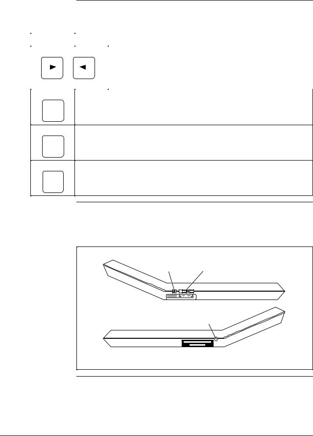
Figure 1-3 shows the STS103 ON/OFF switch and the terminals on the sides of the unit.
Figure 1-3 STS103 Switch and Terminals
Charging ON/OFF
Terminal Switch
Left Side
Communications
Terminal
Right Side
20721
Continued on next page
4/99 |
STS103 Operating Guide |
7 |
1.2STS103 Physical and Functional Description, Continued
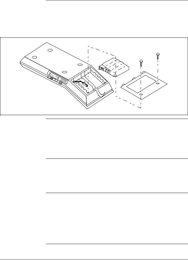
Battery pack location The battery pack is located behind the LCD display and is accessed through a back panel. Two hex screws need to be removed to access the battery pack. Figure 1-4 shows the location of the battery pack and how it fits into the STS103.
Figure 1-4 STS103 Battery Pack
20722
Charging the batteries The battery pack is charged by plugging the battery charger into an outlet and inserting the lead into the charging terminal of the STS103. The battery pack takes a minimum of 10 hours to charge and the STS103 may be used continuously for up to 24 hours before the battery pack needs recharging. A colon (:) will be appear in the middle of the top line on the LCD display when the battery pack needs charging.
STS103 charging terminal
The battery pack is charged through a battery charger that plugs into the charging terminal. The charger inputs 110 or 220 Vac 50/60 Hz and outputs 7 Vdc 180 mA to the NiCd battery pack. The connector of the battery charger is inserted into the charging terminal on left side of the STS103 by the ON/OFF switch.
Self-diagnostics
When the STS103 is turned on, it automatically runs diagnostics on its functions. Upon successful completion of the diagnostics, the message,
“PUT LOOP IN MAN” (analog communications) or “DE-XMTR PRESS ID” (digital communications)
appears. If an error occurs, the message,
“CRITICAL STATUS” appears.
Refer to Section 3 for a description of the STS103 errors or the individual device sections for device specific error messages.
8 |
STS103 Operating Guide |
4/99 |

1.3Connections
Connecting the STS103 to junction boxes and IS panels
The STS103 connects to SFIs, IS panels, and junction boxes through a pair of wires with alligator clips on the ends. The STS103 communications terminal end of the wires has a stereo phone jack connection that is inserted into the communications terminal. The other end of the wires are clipped onto terminals in the junction box or IS barrier panel, or directly to the transmitter. The red SFC lead connects to the junction box or SFI positive terminal, the black lead to the negative terminal.
Figure 1-5 shows the STS103 connected to a junction box and an IS barrier panel.
Figure 1-5 STS103 –Junction Box and IS Connection
Transmitter Junction Box
|
|
well |
well |
ney |
|
Ho |
|
|
Honey |
|
|
IS Panel
20723 |
Connecting the STS103 to a smart field instrument (SFI)
The STS103 connects directly to the positive and negative terminals on the SFI. The STS103 can connect to only one SFI at a time.
REFER TO THE INDIVIDUAL DEVICE SECTIONS IN THIS MANUAL for instructions on how to wire the STS103 to your particular device (SFI).
4/99 |
STS103 Operating Guide |
9 |
1.4STS103/SFI Communication
How data is transferred
Types of communication
Sending and receiving data to and from an SFI is done over the transmitter’s 4-20 mA wires. When the STS103 is connected to a transmitter and turned on, it automatically determines what type of transmitter it is communicating with. When data is sent to a transmitter, a request is sent to the transmitter and a response is sent back to the STS103. When the STS103 and SFI are communicating, the message “SFC Working...” is displayed on the STS103.
The message handling routines are transparent to you. The way the request and response messages are handled depend on whether the transmitter is an analog only model or an analog/digital model, and the mode configuration.
Analog communications uses half duplex communication (data can be sent in one direction at a time, to the transmitter or to the STS103) while the digital communication uses half duplex with or without broadcast (4 or 6 bytes). Table 1-3 describes the communication formats used.
Table 1-3 Communication Format Description
Format |
Description |
|
|
Analog
Communication
Mode
DE READ
A
ID
Digital (DE)
Communication
Mode
DE READ
^A
SHIFT ID
Analog communication uses a half-duplex , variable-length message with a wake-up pulse for on-demand requests and responses. While the messages travel back and forth, the transmitter’s output varies between 4-20 mA, therefore, the control loop must be in manual so the data exchange does not interfere with the control loop.
Digital communication also uses a half-duplex , variablelength message with no wake-up pulse for on-demand requests and responses (not including data uploads). The data is piggybacked on the process variable data being sent on the control loop.
The broadcast 4-byte format is rarely used because no database protection can be performed when used in the TDC 3000 system. This mode is only used when faster PV update rates are required. One byte is for transmitter status and configuration data; the other three are for process data.
The broadcast 6-byte format is used for uploading the transmitter’s database to the STS103’s hold memory. The bytes are similar to the 4-byte format, but it includes two additional bytes of transmitter database information.
Continued on next page
10 |
STS103 Operating Guide |
4/99 |

1.4STS103/SFI Communication, Continued
Analog data exchange When the STS103 communicates with an analog transmitter, a 26 mA wake-up pulse is sent to the transmitter to put the device into the communication mode. The pulse also causes the current drawn by the device to drop to 4 mA. Data is then exchanged in an analog fashion (4-20 mA) between the STS103 and SFI. Figure 1-6 shows a typical analog data exchange using the STS103.
Figure 1-6 |
Typical Analog Data Exchange |
|
|
|
|||
|
|
|
|
|
|
||
|
SFC103 |
|
|
Smart Transmitter |
|
||
|
|
|
|
Request |
|
|
|
|
|
|
Receive Data |
|
|||
|
Send Request |
|
Wake-up Signal and Message |
|
|||
|
|
|
|
|
|||
|
|
|
|
|
|||
|
|
|
|
|
Identify Request |
|
|
|
|
|
|
|
|
||
|
Keypad Action |
|
Response |
|
|
|
|
|
|
|
|
|
|||
|
|
|
|
Process Information |
|
||
|
|
|
|
|
|
||
Message
Display Message
Send Response
|
Wake-up |
|
Data and |
|
|
|
26 mA |
Pulse |
Start |
Stop |
|
|
|
Parity |
|
|
||||
|
|
|
||||
20 mA |
|
|
|
|
|
|
Analog PV |
|
|
|
|
|
Analog PV |
10 mA |
|
|
Request |
|
Response |
|
4 mA |
|
|
|
|
|
|
Turn-On |
|
|
|
Start |
Data and |
Stop |
|
|
|
|
|
||
|
Turn-Off |
|
|
20724 |
||
|
|
|
Parity |
|||
|
|
|
|
|
|
|
Continued on next page
4/99 |
STS103 Operating Guide |
11 |
1.4STS103/SFI Communication, Continued
Digital data exchange |
|
Data exchanges between the STS103 and digital devices are in ASCII. |
||||||||||||||
|
|
|
The exchange starts off with the STS103 requesting the transfer and the |
|||||||||||||
|
|
|
SFI then responds. Figure 1-7 shows a typical digital data exchange using |
|||||||||||||
|
|
|
the STS103 and Table 1-4 Describes the sequence of events. |
|||||||||||||
Figure 1-7 |
Typical Digital Data Exchange |
|
|
|
|
|
|
|
|
|||||||
|
|
|
|
|
|
|
|
|
|
|
|
|
|
|
|
|
|
No. of Bytes 4 |
|
4 |
4 |
4 |
14 |
4 |
|
4 |
4 |
|
|
||||
|
|
|
|
|
||||||||||||
|
Xmtr |
|
|
|
|
5 |
|
|
7 |
8 |
|
|
|
|
|
|
|
|
|
|
|
|
|
|
|
|
|
|
|
||||
|
|
|
|
|
|
|
|
|
|
|
|
|
|
|||
|
|
|
|
|
|
|
|
|
PV and |
|
|
|
|
|
|
|
|
|
|
PV |
|
PV |
|
PV |
PV |
PV |
PV |
|
PV |
||||
|
|
|
|
|
Response |
|
||||||||||
|
|
|
|
|
|
|
|
|
|
|
|
|
|
|
|
|
|
1 |
2 |
3 |
|
|
|
6 |
|
|
|
|
|
|
|
|
|
|
|
|
|
|
|
|
|
|
|
|
|
|||||
|
SFC |
|
|
|
|
|
|
|
|
|
|
|
|
|
|
|
|
4 |
Request and |
|
|
|
|
|
20725 |
|
|||||||
|
|
|
|
|
|
|
|
|||||||||
|
|
Message |
|
|
|
|
|
|
|
|
|
|||||
|
|
|
|
|
|
|
|
|
|
|
|
|
|
|||
|
|
|
|
|
|
|
|
|
|
|
|
|
|
|
|
|
|
|
|
|
|
|
|
|
|
|
|
|
|
|
|
|
|
|
|
|
|
|
|
|
|
|
|
|
|
|
|
|
|
|
Digital data exchange sequence of events
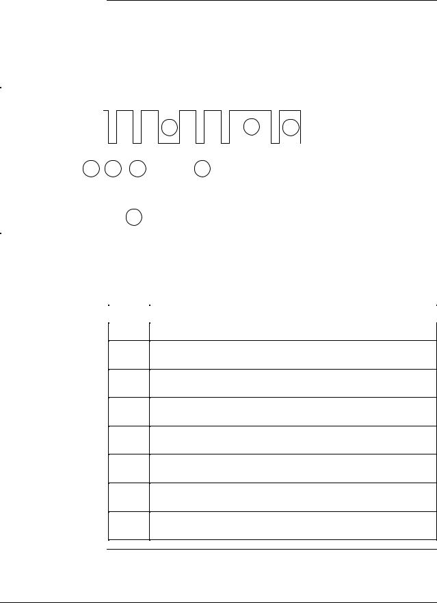
Table 1-4 describes the sequence of events in a typical digital data exchange. The steps correspond to the numbers in Figure 1-7.
Table 1-4 Typical Digital Data Exchange Sequence of Events
Step |
Occurrence |
|
|
1The STS103 waits at least 100 msec for any digital communications.
2The STS103 detects the transmitter message length and gap location.
3The STS103 synchronizes its operation with the next transmitter message.
4The STS103 transmits a request and message during the next intermessage gap.
5The transmitter halts broadcasting process variable (PV) data when the request is detected.
6After receipt of a complete message, the transmitter returns to its configured broadcast mode and processes a response message.
7After completion of processing, the transmitter sends the response message in half duplex protocol after the next PV data broadcast.
8Upon completion of the data transfer, the transmitter returns to its configured broadcast mode within 100 msec.
12 |
STS103 Operating Guide |
4/99 |

Section 2 —STS103 User Interface Guidelines
1.2STS103 Overview
Introduction
What’s in this section?
This section describes the User Interface functions and guidelines for the STS103 Smart Field Communicator (SFC).
There are several features of the STS103 that will make communicating with a Smart Field Instrument (SFI) easier to accomplish. They are:
∙Common operation for all Smart Field Instruments
∙A two-line LCD display
∙A new keypad with improved key responsiveness
∙Direct key access for the “most used” functions
∙Configuration key access for SFI-specific configuration and “lesser used” functions
This section contains the following topics:
|
Topic |
See Page |
|
|
|
|
|
2.1 |
Overview |
13 |
|
2.2 |
Keypad Functions |
14 |
|
|
|||
2.3 |
Display Functions |
15 |
|
|
|||
2.4 |
Prompt Character Definitions |
16 |
|
|
|||
2.5 |
Function Key Data Entry |
17 |
|
|
|||
2.6 |
Configuration Key Data Entry |
19 |
|
|
|||
2.7 |
Other Key Sequences |
21 |
|
|
|||
|
|
|
|
4/99 |
STS103 Operating Guide |
13 |

2.2Keypad Functions
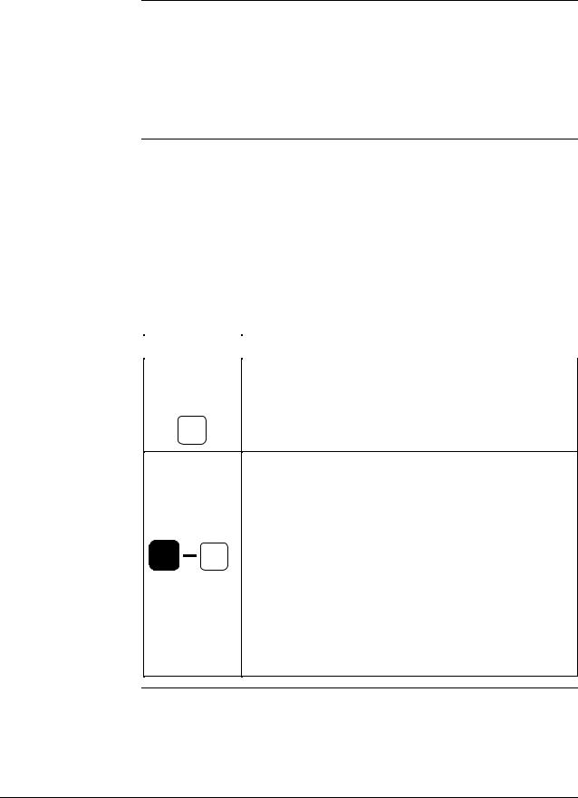
Keypad color groups The keypad keys are grouped in several different colors that correspond to specific functions. Figure 2-1 shows the grouping of the STS103 keys.
Figure 2-1 STS103 Keypad Color Groups
|
|
Green |
|
|
|
|
DE READ |
|
|
|
|
|
A |
B |
C |
D |
|
|
ID |
CONF |
DAMP |
UNITS |
|
|
E |
F |
G |
H |
|
|
LRV |
URV |
SET |
NEXT |
|
|
0% |
100% |
|
Orange |
|
|
DE CONF |
INPUT |
RESET |
|
|
|
I |
J |
K |
L |
|
|
MENU |
OUT- |
COR- |
|
|
|
ITEM |
PUT |
RECT |
PREV |
|
|
M |
N |
O |
P |
|
|
|
7 |
8 |
9 |
|
|
A <–> DE |
|
|
|
|
|
Q |
R |
S |
T |
|
|
|
4 |
5 |
6 |
Yellow |
Olive |
F/S DIR |
|
|
SW VER |
|
|
U |
V |
W |
X |
|
|
STAT |
1 |
2 |
3 |
|
|
URL |
|
SCR PAD |
+ – |
|
|
Y |
Z |
|
|
|
|
SPAN |
0 |
|
|
|
|
|
|
|
NON-VOL |
|
|
NUM / |
SHIFT |
CLR |
ENTER |
Orange |
|
ALPHA |
(NO) |
(YES) |
||
|
White/Black |
20726 |
|
||
|
|
|
|
|
|
Key color group description
Table 2-1 describes the key color grouping on the STS103.
Table 2-1 STS103 Key Color Group Description
Key Color
Green
Description
The green keys are used to enter and verify SFI configuration data.
Orange
Yellow
White/Black
Olive
The orange keys are keys the operator uses to control the actions of the STS103 and SFIs. These keys also select and set parameters for the SFIs.
The primary function of the yellow keys is to enter numeric data into the STS103. Data may be entered into the scratch pad memory of certain SFIs and the software version may be displayed through these keys.
The white and black keys enter the alpha or numeric modes and enable the STS103’s second functions to be activated. CLR (no) key takes you to a previous function level.
The olive keys allow backspacing or advancing in certain modes, switching from analog to digital modes for communicating with different SFIs, and viewing the status of SFIs. Allows viewing of Span and Upper Range Limit.
14 |
STS103 Operating Guide |
4/99 |

2.3Display Functions
LCD display
The STS103 uses a two-line display.
Table 2-2 lists the data that may appear on each line of the display and some examples of each.
Table 2-2 LCD Display Functions
Line |
Display Data |
|
|
Upper Type of transmitter
Tag Name
A label that identifies the value, message, or sub-level title on the lower line.
Configuration sub-level title for which the menu selections or settings are shown on the lower line.
The non critical status indicator
The low battery indicator
Lower Alpha-numeric string for ID name or Scratch Pad entries.
The numerical value and units for the parameter defined on the upper line.
Configuration sub-level title with a “?” indicating that the next configuration level may (“YES”) or may not (“NO”) be selected for viewing.
Examples
MAG SR, LIN DP, STT, etc..
(User defined ID name)
LRV1, OUTPT2, SPT CONFIG, etc.
RANGE CONFIG?,
PROBE CONFIG?
CONFORMITY?, etc.
( # )
( : )
(user defined name or message)
53.99%, 23.121°C, 28.763 Gal/hr, etc.
CONFORMITY?, RANGE CONFIG?, TOTALIZER MENU?, etc.
Pre-set or menu selectable configuration values (Configuration level 2 or 3).
STS103 processor status messages.
STS103 communication status messages.
CURRENT PV: 1,
F/SAFE UPSCALE, VELOCITY,
(for MagneW UNITS KEY), etc.
SFC WORKING...,
READY...,
ENTERED IN SFC, etc.
NO TRANSMITTER RESPONSE, IN OUTPUT MODE, etc.
4/99 |
STS103 Operating Guide |
15 |

2.4Prompt Character Definitions
Definitions and general rules
Certain characters on the LCD display indicate to you which type of response is permitted.
Table 2-3 shows these characters and the rules and what the STS103 is looking for in the way of input.
Table 2-3
Character
“ _ ”
“ = “
“ ? ”
“ * “
STS103 LCD Character Definitions and General Rules
Display Example
When the display contains a cursor, for example,
LRV = 1.22
When the display shows an item after an equal (=) sign, for example,
F/S = B/O Lo
When the display shows an item with a question mark (?) after the item, for example,
Range Config?
When the display shows an item with
a “ * “, for example:
ABC *
Requested Action
The STS103 is asking you to enter a numerical value at the cursor point.
Type in a new value and press the ENTER
key to store the value.
Numeric entries are also allowed in the ID name and Scratch Pad messages.
The STS103 is asking for a selection after the equal sign.
Your selection can be made using the
|
key or the |
|
|
|
or |
|
|
|
keys |
MENU |
|
|
|
|
|
|
from a pre-defined list of values or selections.
The STS103 is asking if you want to enter a particular group of configuration parameters.
If the parameters are what you desire, press
the YES key.
Press the CLR key to cancel from the
current configuration level and return the SFC display to the next highest configuration level.
Press NEXT or PREV to go on to the
next or previous group of parameters.
The STS103 is asking you to enter an alpha character.
This prompt is used only when entering an ID name or Scratch Pad messages.
Continued on next page
16 |
STS103 Operating Guide |
4/99 |

2.5Function Keys Data Entry
Function keys
Multiple process variables
To access the basic functions or parameters which are common to all SFIs, press any one of the labeled function keys. These common items are:
•ID
•SPAN/LRV/URV/URL
•INPUT/OUTPUT
•INPUT and OUTPUT CORRECTS
•LRV and URV CORRECTS and SETS
•RESET CORRECTS
•STATUS
•UNITS
•DAMPING
•FAILSAFE DIRECTION
•DE OPERATIONS
•SW VERSION
•SCRATCH PAD
In some cases, more than one Process Variable is available. Press the
MENU key to select which PV will be referenced when the following operating parameters are displayed:
•SPAN/LRV/URV/URL/LRL
•INPUT/OUTPUT
•DAMP
•UNITS
For example, consider an SFI that may analyze up to four components.
Each time the MENU key is pressed, the display will step through the
available Process Variables (PVs)-(CURRENT PV:1, CURRENT PV:2, CURRENT PV:3, CURRENT PV:4).
If PV:2 were selected and the SPAN key pressed, “SPAN 2” (the span for input 2) would be displayed.
Continued on next page
4/99 |
STS103 Operating Guide |
17 |
2.5Function Keys Data Entry, Continued
Function key sequence Most of the common operating parameters are numerical values which may be altered by the operator. To display and/or change these values, follow the key sequence procedure in Table 2-4.
Table 2-4 Function Key Sequence
Step
1
2
3
4
Action
Press the desired Function key. The display will show the current setting or value of the selected parameter.
A numerical value may be changed only if the first digit of the currently displayed value is underlined.
Enter a new value by pressing the appropriate number keys.
For some values, such as Damping, the 

 and
and 
 keys may be used to step through a menu of permitted selections.
Press the ENTER (yes) key to store the new data in the STS103.
ATTENTION If the operator exits the display using any other key, the data will not be downloaded to the SFI.
The CLR key may be used at any time to return to the normal
operating display without making any changes.
18 |
STS103 Operating Guide |
4/99 |
 Loading...