


Safety Manager
Table of contents
 Loading...
Release 131
Safety Manager
Safety Manual
EP-SM.MAN.6283
Issue 4
10 July 2008

Document Release Issue Date
EP-SM.MAN.6283 131 4 July 2008
Notice
This document contains Honeywell proprietary information. Information
contained herein is to be used solely for the purpose submitted, and no part of this
document or its contents shall be reproduced, published, or disclosed to a third
party without the express permission of Honeywell Safety Management Systems.
While this information is presented in good faith and believed to be accurate,
Honeywell disclaims the implied warranties of merchantability and fitness for a
purpose and makes no express warranties except as may be stated in its written
agreement with and for its customer.
In no event is Honeywell liable to anyone for any direct, special, or consequential
damages. The information and specifications in this document are subject to
change without notice.
Copyright 2008 – Honeywell Safety Management Systems, a division of
Honeywell Aerospace B.V.
Honeywell trademarks
Experion PKS
U.S. registered trademarks of Honeywell International Inc.
®
, PlantScape®, SafeBrowse®, TotalPlant® and TDC 3000® are
Conventions
ii
Other trademarks
Microsoft and SQL Server are either registered trademarks or trademarks of
Microsoft Corporation in the United States and/or other countries.
Trademarks that appear in this document are used only to the benefit of the
trademark owner, with no intention of trademark infringement.
Symbols
The following symbols are used in Safety Manager documentation:
Attention
This symbol is used for information that emphasizes or supplements important points of
the main text.
Tip
This symbol is used for useful, but not essential, suggestions.
Note
This symbol is used to emphasize or supplement important points of the main text.
Caution
This symbol warns of potential damage, such as corruption of the database.
Warning
This symbol warns of potentially hazardous situations, which, if not avoided, could result
in serious injury or death.
ESD
This symbol warns for danger of an electro-static discharge to which equipment may be
sensitive.
iii

Fonts
The following fonts are used in Safety Manager documentation:
Emphasis
• “... inform the reader on how to perform
the task in terms of...”
• “...see the Overview Guide”
Label
“The Advanced tab of the Properties
window has..”
Steps
Take the following steps:
1. Create a plant and set its properties.
2. ....
User Variable
..create the My Projects folder and
store the readme.txt file here.
..press the Tab key..
Next press Enter to..
Value
“Low is the fault reaction state for digital
inputs and digital outputs.”
Variable
“The syntax is: filename [-s] [-p]“
http://www.honeywellsms.com This font is used to identify a URL, directing
Emphasised text is used to:
• emphasise important words in the text,
• identify document titles.
This font is used to identify labels and titles
of (popup) windows.
Labels are used for Dialog box labels, menu
items, names of properties, and so on.
This font is used to identify steps.
Steps indicate the course of action that must
be adhered to, to achieve a certain goal.
This font is used to:
1. identify a user variable, a filename, an
object or view.
2. highlight the keys the user should press on
the keyboard.
User variable is a variable, an object or
a view that the reader can call-up to view or
to manipulate.
This font is used to indicate a value.
Value is a variable that the reader must
resolve by choosing a pre-defined state.
This font is used to identify a variable.
Variables are used in syntax and code
examples.
a reader to a website that can be referred to.
iv

Contents
1The Safety Manual 1
Content of Safety Manual . . . . . . . . . . . . . . . . . . . . . . . . . . . . . . . . . . . . . . . . . . . . . . . . . . . . . . . 1
References . . . . . . . . . . . . . . . . . . . . . . . . . . . . . . . . . . . . . . . . . . . . . . . . . . . . . . . . . . . . . 2
Basic skills and knowledge . . . . . . . . . . . . . . . . . . . . . . . . . . . . . . . . . . . . . . . . . . . . . . . . . . . . . . 3
Prerequisite skills. . . . . . . . . . . . . . . . . . . . . . . . . . . . . . . . . . . . . . . . . . . . . . . . . . . . . . . . 3
Training . . . . . . . . . . . . . . . . . . . . . . . . . . . . . . . . . . . . . . . . . . . . . . . . . . . . . . . . . . . . . . . 3
Safety standards for Process & Equipment Under Control (PUC, EUC) . . . . . . . . . . . . . . . . . . . 4
Safety Integrity level (SIL) . . . . . . . . . . . . . . . . . . . . . . . . . . . . . . . . . . . . . . . . . . . . . . . . 4
Application design conform IEC 61131-3. . . . . . . . . . . . . . . . . . . . . . . . . . . . . . . . . . . . . 4
The IEC 61508 and IEC 61511 standards . . . . . . . . . . . . . . . . . . . . . . . . . . . . . . . . . . . . . 5
2 Architectural principle and standards of Safety Manager 9
Safety Manager basic architectures. . . . . . . . . . . . . . . . . . . . . . . . . . . . . . . . . . . . . . . . . . . . . . . . 9
Dual Modular Redundant (DMR) architecture . . . . . . . . . . . . . . . . . . . . . . . . . . . . . . . . . 9
Quadruple Modular Redundant (QMR) architecture . . . . . . . . . . . . . . . . . . . . . . . . . . . 10
Watchdog architecture in mixed IO configurations. . . . . . . . . . . . . . . . . . . . . . . . . . . . . 11
Certification. . . . . . . . . . . . . . . . . . . . . . . . . . . . . . . . . . . . . . . . . . . . . . . . . . . . . . . . . . . . . . . . . 13
Standards compliance . . . . . . . . . . . . . . . . . . . . . . . . . . . . . . . . . . . . . . . . . . . . . . . . . . . . . . . . . 15
3 Safety Manager fault detection and response 19
Introduction . . . . . . . . . . . . . . . . . . . . . . . . . . . . . . . . . . . . . . . . . . . . . . . . . . . . . . . . . . . . . . . . . 19
Diagnostic Test Interval. . . . . . . . . . . . . . . . . . . . . . . . . . . . . . . . . . . . . . . . . . . . . . . . . . 19
FR state . . . . . . . . . . . . . . . . . . . . . . . . . . . . . . . . . . . . . . . . . . . . . . . . . . . . . . . . . . . . . . 19
Repair timer. . . . . . . . . . . . . . . . . . . . . . . . . . . . . . . . . . . . . . . . . . . . . . . . . . . . . . . . . . . 20
Shutdown at assertion of Safety Manager alarm markers . . . . . . . . . . . . . . . . . . . . . . . . 21
SM Controller faults . . . . . . . . . . . . . . . . . . . . . . . . . . . . . . . . . . . . . . . . . . . . . . . . . . . . . . . . . . 22
QPP faults . . . . . . . . . . . . . . . . . . . . . . . . . . . . . . . . . . . . . . . . . . . . . . . . . . . . . . . . . . . . 22
BKM faults . . . . . . . . . . . . . . . . . . . . . . . . . . . . . . . . . . . . . . . . . . . . . . . . . . . . . . . . . . . 24
PSU faults . . . . . . . . . . . . . . . . . . . . . . . . . . . . . . . . . . . . . . . . . . . . . . . . . . . . . . . . . . . . 24
Communication faults . . . . . . . . . . . . . . . . . . . . . . . . . . . . . . . . . . . . . . . . . . . . . . . . . . . 25
SM IO faults . . . . . . . . . . . . . . . . . . . . . . . . . . . . . . . . . . . . . . . . . . . . . . . . . . . . . . . . . . . . . . . . 27
Digital input faults. . . . . . . . . . . . . . . . . . . . . . . . . . . . . . . . . . . . . . . . . . . . . . . . . . . . . . 27
Analog input faults . . . . . . . . . . . . . . . . . . . . . . . . . . . . . . . . . . . . . . . . . . . . . . . . . . . . . 28
Digital output faults. . . . . . . . . . . . . . . . . . . . . . . . . . . . . . . . . . . . . . . . . . . . . . . . . . . . . 28
Analog output faults . . . . . . . . . . . . . . . . . . . . . . . . . . . . . . . . . . . . . . . . . . . . . . . . . . . . 29
Calculation errors . . . . . . . . . . . . . . . . . . . . . . . . . . . . . . . . . . . . . . . . . . . . . . . . . . . . . . . . . . . . 34
Safety Manager Safety Manual v

Contents
4 Safety Manager special functions 37
Unit shutdown . . . . . . . . . . . . . . . . . . . . . . . . . . . . . . . . . . . . . . . . . . . . . . . . . . . . . . . . . . . . . . . 37
Process units . . . . . . . . . . . . . . . . . . . . . . . . . . . . . . . . . . . . . . . . . . . . . . . . . . . . . . . . . . 37
Configuration of unit shutdown (watchdog grouping) . . . . . . . . . . . . . . . . . . . . . . . . . . 37
Unit shutdown outputs. . . . . . . . . . . . . . . . . . . . . . . . . . . . . . . . . . . . . . . . . . . . . . . . . . . 39
Process outputs (safety related). . . . . . . . . . . . . . . . . . . . . . . . . . . . . . . . . . . . . . . . . . . . 39
Application programming . . . . . . . . . . . . . . . . . . . . . . . . . . . . . . . . . . . . . . . . . . . . . . . . 39
On-line modification . . . . . . . . . . . . . . . . . . . . . . . . . . . . . . . . . . . . . . . . . . . . . . . . . . . . . . . . . . 41
SafeNet communication . . . . . . . . . . . . . . . . . . . . . . . . . . . . . . . . . . . . . . . . . . . . . . . . . . . . . . . 42
Networks . . . . . . . . . . . . . . . . . . . . . . . . . . . . . . . . . . . . . . . . . . . . . . . . . . . . . . . . . . . . . 42
Protocol versus response time . . . . . . . . . . . . . . . . . . . . . . . . . . . . . . . . . . . . . . . . . . . . . 42
Reset . . . . . . . . . . . . . . . . . . . . . . . . . . . . . . . . . . . . . . . . . . . . . . . . . . . . . . . . . . . . . . . . . . . . . . 44
5 Special requirements for TUV-approved applications 47
General . . . . . . . . . . . . . . . . . . . . . . . . . . . . . . . . . . . . . . . . . . . . . . . . . . . . . . . . . . . . . . . . . . . . 47
F&G applications . . . . . . . . . . . . . . . . . . . . . . . . . . . . . . . . . . . . . . . . . . . . . . . . . . . . . . . . . . . . 51
vi Release 131, Issue 4
The Safety Manual
Content of Safety Manual
The Safety Manual is a reference guide providing detailed information regarding
safety aspects in Safety Manager.
A reference guide is a Safety Manager related guide and does not describe tasks
in terms of how to perform the task in terms of steps to follow. A reference guide
can provide input to support decisions required to achieve a certain objective.
Guide subjects
Safety Manual
• “Architectural principle and standards of Safety Manager” on
page 9
• “Safety Manager fault detection and response” on page 19
• “Safety Manager special functions” on page 37
• “Special requirements for TUV-approved applications” on page 47
1
Safety Manager Safety Manual 1

1 – The Safety Manual
References
The following guides may be required as reference materials:
Guide Description
The Overview Guide This guide describes the general knowledge required, the
The Planning and Design
Guide
The Installation and Upgrade
Guide
The Troubleshooting and
Maintenance Guide
The System Administration
Guide
The On-line Modification
Guide
The Hardware Reference This guide specifies the hardware components that build a
The Software Reference This guide specifies the software functions that build a
basic functions of, and the tasks related to Safety
Manager.
This guide describes the tasks related to planning and
designing a Safety Manager project.
This guide describes the tasks related to installing,
replacing and upgrading hardware and software as part of
a Safety Manager project.
This guide describes the tasks related to troubleshooting
and maintaining Safety Manager.
This guide describes the task related to administrating the
computer systems used in a Safety Manager project.
This guide describes the theory, steps and tasks related to
upgrading Safety Builder and embedded software and
modifying an application online in a redundant Safety
Manager.
Safety Manager project.
Safety Manager project and contains guidelines on how to
operate them.
2 Release 131, Issue 4

Basic skills and knowledge
Before performing tasks related to Safety Manager you need to:
• Understand basic Safety Manager concepts as explained in the Overview
Guide and the Glossary.
• Have a thorough understanding of the Safety Manual.
• Have had appropriate training related to Safety Manager that certifies you for
your tasks (see the Planning and Design Guide).
Prerequisite skills
When you perform tasks related to Safety Manager, it is assumed that you have
appropriate knowledge of:
• Site procedures
• The hardware and software you are working with. These may i.e. be:
computers, printers, network components, Controller and Station software.
• Microsoft Windows operating systems.
• Programmable logic controllers (PLCs).
• Applicable safety standards for Process & Equipment Under Control.
• Application design conform IEC 61131-3.
• The IEC 61508 and IEC 61511 standards.
This guide assumes that you have a basic familiarity with the process(es)
connected to the equipment under control and that you have a complete
understanding of the hazard and risk analysis.
Basic skills and knowledge
Training
Most of the skills mentioned above can be achieved by appropriate training. For
more information, contact your Honeywell SMS representative or see:
• http://www.automationcollege.com.
Safety Manager Safety Manual 3

1 – The Safety Manual
Safety standards for Process & Equipment Under Control (PUC, EUC)
Safety Integrity level (SIL)
The IEC 61508 standard specifies 4 levels of safety performance for safety
functions. These are called safety integrity levels. Safety integrity level 1 (SIL1)
is the lowest level of safety integrity, and safety integrity level 4 (SIL4) the
highest level. If the level is below SIL1, the IEC 61508 and IEC 61511 do not
apply.
Safety Manager can be used for processing multiple SIFs simultaneously
demanding a SIL1 up to and including SIL3.
To achieve the required safety integrity level for the E/E/PE safety-related
systems, an overall safety life cycle is adopted as the technical framework (as
defined in IEC 61508).
Application design conform IEC 61131-3
The IEC 61131 standard defines, as a minimum set, the basic programming
elements, syntactic and semantic rules for the most commonly used programming
languages, including graphical languages of:
• Ladder Diagram,
• Functional Block Diagram and,
• Textual languages of Instruction List and structured Text;
For more information see the IEC web site.
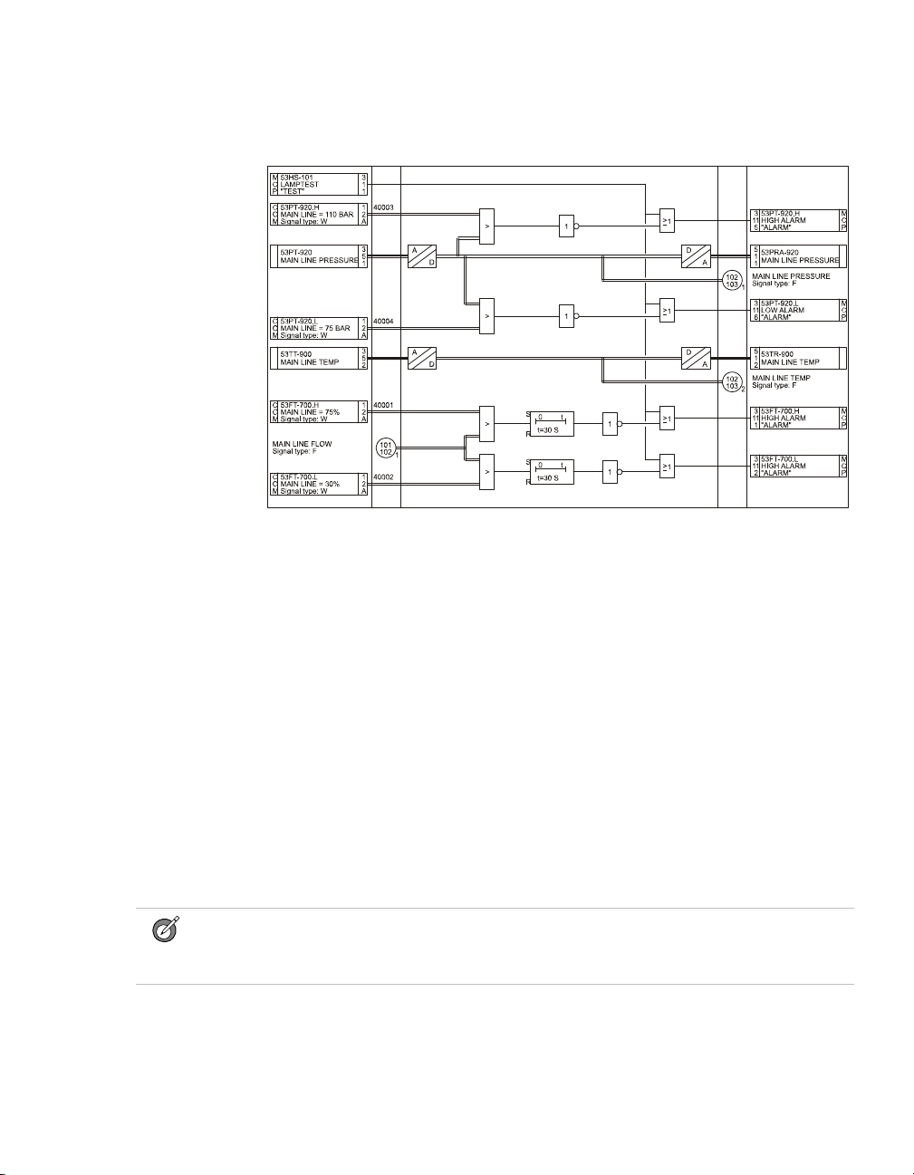
Figure 1 on page 5 shows how Safety Manager uses the graphical programming
method, based on Functional Block Diagram as defined by the IEC 61131-3.
4 Release 131, Issue 4
Safety standards for Process & Equipment Under Control (PUC, EUC)
Figure 1 Example FLD layout
The IEC 61508 and IEC 61511 standards
SISs have been used for many years to perform safety instrumented functions e.g.
in chemical, petrochemical and gas plants. In order for instrumentation to be
effectively used for safety instrumented functions, it is essential that the
instrumentation meets certain minimum standards and performance levels.
To define the characteristics, main concepts and required performance levels,
standards IEC 61508 and IEC 61511 have been developed. The introduction of
Safety Integrity level (SIL) is one of the results of these standards.
This brief provides a short explanation of each standard. Detailed information
regarding IEC 61508 and 61511 can be found on the IEC web site
http://www.iec.org.
What standard to use?
Tip:
You can use the IEC 61508 as stand-alone standard for those sectors where a sector
specific standard does not exist.
Safety Manager Safety Manual 5
1 – The Safety Manual
• If you are in the process sector and you are an owner/user, it is strongly
recommended that you pay attention to the IEC 61511 (ANSI/ISA 84.00.01).
For details see “IEC 61511, the standard for the process industry” on page 7.
• If you are in the process sector and you are a manufacturer, it is strongly
recommended that you pay attention to the IEC 61508. For details see “IEC
61508, the standard for all E/E/PE safety-related systems” on page 6.
• If you are in another sector, it is strongly recommended that you look for, and
use, your sector specific IEC standard for functional safety (if there is one). If
none exists, you can use the IEC 61508 instead. For details see “IEC 61508,
the standard for all E/E/PE safety-related systems” on page 6
IEC 61508 and IEC 61511 terminology
This guide contains both IEC 61508 and IEC 61511 related terminology.
As the IEC 61511 sits within the framework of IEC 61508 most of the
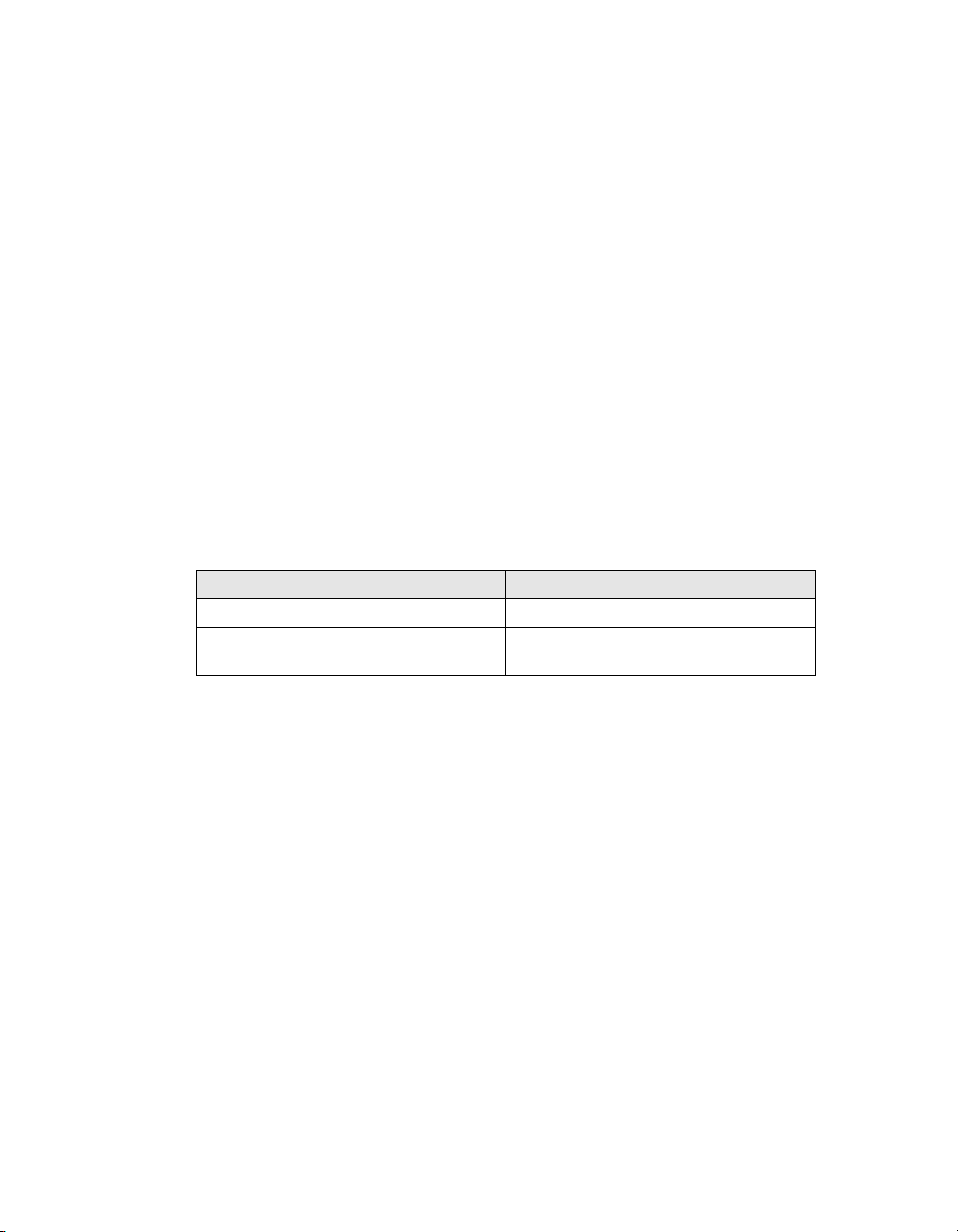
terminology used may be interchanged. Table 1 on page 6 provides an overview
of the most common interchangeable terminology.
IEC 61508 terminology IEC 61511 terminology
safety function safety instrumented function
electrical/electronic/programmable
electronic (E/E/PE) safety-related system
Tab le 1 IEC 61508 versus IEC 61511 terminology
safety instrumented system (SIS)
IEC 61508, the standard for all E/E/PE safety-related systems
The IEC 61508 is called “Functional safety of
electrical/electronic/programmable electronic safety-related systems”
IEC 61508 covers all safety-related systems that are electrotechnical in nature
(i.e. electromechanical systems, solid-state electronic systems and
computer-based systems).
Generic standard
The standard is generic and is intended to provide guidance on how to develop
E/E/PE safety related devices as used in Safety Instrumented Systems (SIS).
The IEC 61508:
• serves as a basis for the development of sector standards (e.g. for the
machinery sector, the process sector, the nuclear sector, etc.).
• can serve as stand-alone standard for those sectors where a sector specific
standard does not exist.
6 Release 131, Issue 4

Safety standards for Process & Equipment Under Control (PUC, EUC)
SIL
IEC 61508 details the design requirements for achieving the required Safety
Integrity Level (SIL).
The safety integrity requirements for each individual safety function may differ.
The safety function and SIL requirements are derived from the hazard analysis
and the risk assessment.
The higher the level of adapted safety integrity, the lower the likelihood of
dangerous failure of the SIS.
This standard also addresses the safety-related sensors and final elements
regardless of the technology used.
IEC 61511, the standard for the process industry
The IEC 61511 is called “Functional safety - Safety instrumented systems for the
process industry sector”. It is also referred to as the ANSI/ISA 84.00.01.
This standard addresses the application of SISs for the process industries. It
requires a process hazard and risk assessment to be carried out, to enable the
specification for SISs to be derived. In this standard a SIS includes all
components and subsystems necessary to carry out the safety instrumented
function from sensor(s) to final element(s).
The standard is intended to lead to a high level of consistency in underlying
principles, terminology and information within the process industries. This
should have both safety and economic benefits.
The IEC 61511 sits within the framework of IEC 61508.
Need to know more?
For more information regarding, or help on, implementing or determining, the
applied safety standards for your plant/process please contact your Honeywell
affiliate. Our Safety Consultants can help you to e.g.:
• perform a hazard risk analysis
• determine the SIL requirements
• design the Safety Instrumented System
• validate and verify the design
• train your local safety staff
Safety Manager Safety Manual 7

1 – The Safety Manual
8 Release 131, Issue 4

Architectural principle and standards of Safety Manager
Safety Manager basic architectures
Safety Manager can be configured for a number of architectures, each with its
own characteristics and typical Safety Instrumented Functions. Table 2 on page 9
provides an overview of the available architectures.
Tab le 2 Safety Manager architectures
Controller
configuration
Non-redundant
(DMR)
Redundant
(QMR)
IO configuration Remarks
Non-redundant DMR architecture;
• Non-redundant
• Redundant
• Redundant and non-redundant
2
Supports SIF for SIL1,
SIL2 and SIL3
applications.
QMR architecture;
Supports SIF for SIL1,
SIL2 and SIL3
applications.
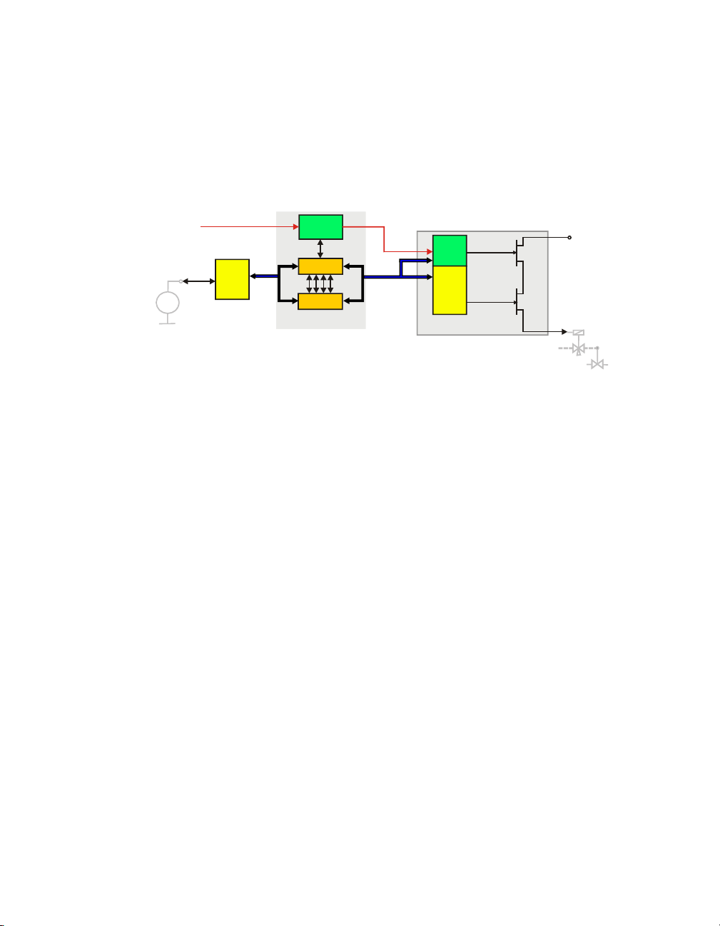
Dual Modular Redundant (DMR) architecture
Typical applications of a DMR architecture are:
• Burner Management System
• Batch processing
• Machine protection
The Dual Modular Redundant (DMR) architecture provides 1oo2 voting in a
non-redundant system. The DMR architecture with 1oo2 voting is based on
dual-processor technology, and is characterized by a high level of self tests,
diagnostics and fault tolerance.
Safety Manager Safety Manual 9
2 – Architectural principle and standards of Safety Manager
Processor
Processor
Watchdog
QPP Control Processor
SD
Input Interfaces Output Interfaces
Input
Module
Sensor
xx
yyy
Final Element
SMOD
Output
Module
The DMR architecture is realized with a non-redundant Controller. A
non-redundant architecture contains only one QPP (see Figure 2 on page 10),
which contains a redundant processor with 1oo2 voting between the processors
and memory.
Figure 2 Functional diagram: DMR architecture
In IO configurations, each path is primarily controlled by the Control Processor
and an independent switch (Secondary Means of De-energization, SMOD) which
is controlled by an independent watchdog.
Quadruple Modular Redundant (QMR) architecture
Typical applications of a QMR architecture are:
• process safeguarding applications for which continues operation is essential.
The Quadruple Modular Redundant (QMR) architecture is based on 2oo4D
voting, dual-processor technology in each QPP. This means that it is characterized
by a ultimate level of self diagnostics and fault tolerance.
The QMR architecture is realized with a redundant Controller. This redundant
architecture contains two QPPs (see Figure 3 on page 11), which results in
quadruple redundancy making it dual fault tolerant for safety.
The 2oo4D voting is realized by combining 1oo2 voting of both CPUs and
memory in each QPP, and 1oo2D voting between the two QPPs. Voting takes
place on two levels: on a module level and between the QPPs.
10 Release 131, Issue 4
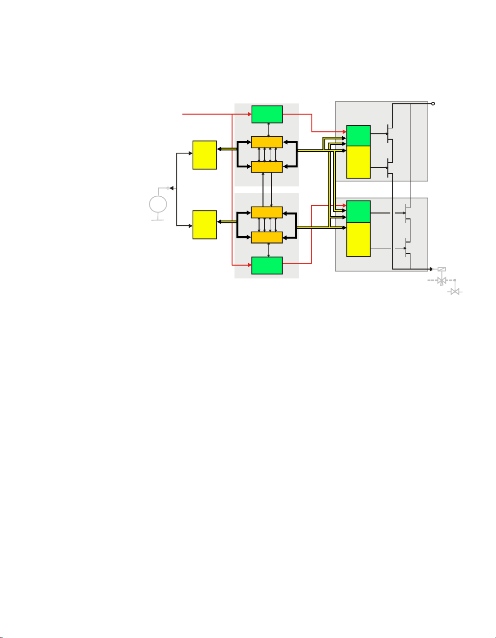
Figure 3 Functional diagram: QMR architecture
Input
Module
Input
Module
Processor
Processor
Watchdog
QPP Control Processor 1
QPP Control Processor 2
SD
Input Interfaces
SMOD
Output
Module
Final Element
Output Interfaces
SMOD
Output
Module
Quad
Vot er
Processor
Processor
Watchdog
Sensor
xx
yyy
In redundant IO configurations, each path is controlled by one of the Control
Processors and an independent switch (Secondary Means of De-energization,
SMOD), which is controlled by the diagnostic software and an independent
watchdog.
Furthermore, each Control Processor is able to switch off the output channels of
the other Control Processor.
Watchdog architecture in mixed IO configurations
In a system with combined redundant and non redundant IO 3 watchdog lines are
active:
• WD1
This is the Watchdog line dedicated for Control Processor 1.
- De-energizes upon a safety related fault in Control Processor 1 or an
output module of Control Processor 1.
- When de-energized, Control Processor 1 and the related outputs are halted.
•WD2
This is the Watchdog line dedicated for Control Processor 2.
Safety Manager Safety Manual 11

2 – Architectural principle and standards of Safety Manager
Input
Module
Input
Module
Processor
Processor
Watchdog
QPP Control Processor 1
QPP Control Processor 2
SD
Input Interfaces
SMOD
Output
Module
Final Element
Output Interfaces
SMOD
Output
Module
Quad
Vote r
Processor
Processor
Watchdog
Input
Module
Final Element
SMOD
Output
Module
Sensor
xx
yyy
Sensor
xx
yyy
- De-energizes upon a safety related fault in Control Processor 2 or an
output module of Control Processor 2.
- When de-energized, Control Processor 2 and the related outputs are halted.
• WD3
This is the combined watchdog line, controlled by both Control Processors.
- De-energizes upon a safety related fault in a non redundant output.
- When de-energized, the non-redundant outputs are de-energized, but the
redundant outputs and the Control Processors remain operational.
Figure 4 Functional diagram: redundant Controller with redundant and non-redundant IO
12 Release 131, Issue 4
Loading...