


Operating Instructions
Searchpoint Optima Plus
Infrared Point Gas Detector

MAN0551 |
Issue 07 - 09/08 |
2108M0501 |
|
total environmental solutions
Ensure that you read and understand these Operating Instructions BEFORE installing or operating any part of the Searchpoint Optima Plus.
Please pay particular attention to the Safety Warnings.
Warnings
1.For installations in the UK, the Code of Practice SELECTION, INSTALLATION AND MAINTENANCE OF ELECTRICAL APPARATUS FOR USE IN POTENTIALLY EXPLOSIVE ATMOSPHERES should be strictly observed. General recommendations are given in BS5345: Part 1: 1989. Specific requirements for flameproof (Type 'd'), intrinsically safe (Type 'i') and increased safety (Type 'e') protection are given in BS 5345: Part 3: 1979, BS 5345: Part 4: 1977 and BS5345: Part 6: 1978 respectively.
For installations in North America, the National
Electrical Code (NFPA 70 - 1990) or later issues should be strictly observed.
Elsewhere the appropriate local or national regulations should be used.
2.The Code of Practice regarding SELECTION, INSTALLATION, USE AND MAINTENANCE OF APPARATUS FOR THE DETECTION AND MEASUREMENT OF COMBUSTIBLE GASES
(OTHER THAN FOR MINING APPLICATIONS OR EXPLOSIVES PROCESSING AND MANUFACTURE) must be complied with. Refer to BS6959:1988 in the UK or the appropriate local or national regulations.
3.Operators must be fully aware of the action to be taken if the gas concentration exceeds an alarm level.
2

MAN0551 |
Issue 07 - 09/08 |
2108M0501 |
|
total environmental solutions
CAUTIONS
1.Use only approved parts and accessories with the
Searchpoint Optima equipment.
2.To maintain safety standards, a planned maintenance programme is strongly recommended. This maintenance programme should take account of all operational conditions and requirements. Maintenance and service operations should only be performed by personnel qualified to work upon Searchpoint Optima
Plus.
3.In order to maintain electrical safety, the unit must not be operated in atmospheres with more than 21% oxygen.
IMPORTANT NOTICES
1.Honeywell Analytics Limited can take no responsibility for installation and/or use of its equipment if this is not done in accordance with the appropriate issue and/or amendment of the manual.
2.The user of this manual should ensure that it is appropriate in all details to the exact equipment to be installed and/or operated. If in doubt, the user should contact Honeywell Analytics Limited for advice.
3.If further details are required which do not appear in this manual, contact Honeywell Analytics Limited or one of their agents.
4.The Searchpoint Optima System is certified for and intended for use in potentially hazardous areas. Install and use the Searchpoint Optima System in accordance with the latest regulations.
Honeywell Analytics Limited reserve the right to change or revise the information supplied in this document without notice and without obligation to notify any person or organisation of such revision or change.
3

MAN0551 |
Issue 07 - 09/08 |
2108M0501 |
|
Help us to help you
Every effort has been made to ensure the accuracy in the contents of our documents, however, Honeywell Analytics Limited can assume no responsibility for any errors or omissions in our documents or their consequences.
Honeywell Analytics Limited would greatly appreciate being informed of any errors or omissions that may be found in the contents of any of our documents and to this end we include the form opposite for you to photocopy, complete and return to us so that we may take the appropriate action.
4
MAN0551 |
Issue 07 - 09/08 |
2108M0501 |
|
|
|
|
|
5
MAN0551 |
|
|
Issue 07 - 09/08 |
|
2108M0501 |
|
|
|
|
|
|
|
|
|
|
|
CONTENTS |
|
|
|
|
|
|
|
Section |
|
|
Page |
|
1. |
INTRODUCTION |
10 |
||
|
1.1 |
General |
10 |
|
2. |
INSTALLATION VARIATIONS |
14 |
||
|
2.1 |
ATEX Units |
14 |
|
|
2.2 |
UL and CSA Units Only |
15 |
|
3. |
INSTALLATION |
17 |
||
|
3.1 |
Unpacking |
17 |
|
|
3.2 |
Siting and Orientation |
17 |
|
|
3.3 |
Installation Guide |
18 |
|
|
3.4 |
Attachments and Options |
22 |
|
|
|
3.4.1 |
General |
22 |
|
|
3.4.2 |
Standard Weather Protection |
22 |
|
|
3.4.3 |
Sunshade/Deluge Protection |
22 |
|
|
3.4.4 |
Storm Baffle |
23 |
|
|
3.4.5 |
Dust Barrier |
23 |
|
|
3.4.6 |
Calibration Cap |
24 |
|
|
3.4.7 |
Gassing Cover |
24 |
|
|
3.4.8 |
Flow Housing |
25 |
|
|
3.4.9 |
Remote Gassing Cell |
26 |
|
|
3.4.10 Junction Box Adaptor Plate |
27 |
|
|
|
3.4.11 |
European Duct Mounting Kit |
28 |
|
|
3.4.12 |
US Duct Mounting Kit |
31 |
6
MAN0551 |
|
|
Issue 07 - 09/08 |
2108M0501 |
|
|
|
|
|
|
|
|
|
CONTENTS |
|
|
|
|
|
Section |
|
Page |
|
4. |
ELECTRICAL CONNECTIONS |
35 |
|
|
4.1 |
General |
35 |
|
4.2 |
Analogue Connection |
40 |
|
4.3 |
Digital Connection |
40 |
|
4.4 |
+24V Power Connection |
41 |
|
4.5 |
Earth Connection |
41 |
5. |
COMMISSIONING |
46 |
|
|
5.1 |
General |
46 |
5.2Commissioning Procedure using SHC-1
and Multimeter |
47 |
|
5.2.1 Electrical Commissioning and Tests |
47 |
|
5.2.2 |
Gas Response Testing |
48 |
5.2.3 |
System Level Testing |
49 |
5.2.4 |
Final Commissioning |
51 |
5.3Commissioning Procedure with Multimeter
Only |
|
52 |
5.3.1 |
Electrical Commissioning and Tests |
|
|
(Multimeter) Only |
52 |
5.3.2 |
Gas Response Testing (Multimeter) |
|
|
Only |
54 |
5.3.3 |
System Level Testing |
55 |
5.3.4 |
Final Commissioning (Multimeter) |
56 |
5.4 Control System Setup |
57 |
|
5.5Functional Response Checking and
Calibration |
57 |
7
MAN0551 |
|
|
|
Issue 07 - 09/08 |
2108M0501 |
|
|
|
|
|
|
|
|
|
|
|
CONTENTS |
|
|
|
|
|
|
|
Section |
|
|
Page |
|
6. |
CALIBRATION |
59 |
||
|
6.1 |
General |
59 |
|
|
6.2 |
SHC-1 Hand-Held Interrogator |
60 |
|
|
|
6.2.1 |
Connecting the Hand-Held |
|
|
|
|
Interrogator |
61 |
|
|
6.2.2 |
Hand-Held Interrogator Operating |
|
|
|
|
Modes |
62 |
|
|
6.2.3 |
Other Hand-Held Features |
66 |
|
6.3 |
Calibrating the Controller |
70 |
|
|
6.4 |
Calibrating the Sensor |
73 |
|
7. |
ROUTINE CHECKS |
81 |
||
|
7.1 |
General |
81 |
|
7.2Inspection and Functional Response Check
Procedure |
81 |
|
7.2.1 |
Response Check Using Gassing Cover |
|
|
and %LEL Concentration Gas |
83 |
7.2.2 |
Response Check Using Remote |
|
|
Gassing Cell & High %VV Gas |
87 |
7.3Inspection and Testing of Units Installed
in Ducts |
92 |
|
7.4 Removal and Refitting of Flow Housing |
94 |
|
7.4.1 |
Removal of Flow Housing |
94 |
7.4.2 |
Refitting of Flow Housing |
94 |
8
MAN0551 |
|
Issue 07 - 09/08 |
2108M0501 |
|
|
|
|
|
|
CONTENTS |
|
|
|
|
Section |
Page |
|
8. |
FAULT FINDING |
97 |
|
8.1 Troubleshooting |
97 |
8.2Diagnosis of Warning and Fault Messages 103
9.REPLACEMENT OF HAND-HELD
|
INTERROGATOR BATTERY |
111 |
|
10. |
ORDERING DETAILS |
113 |
|
11. |
SPECIFICATION |
117 |
|
|
11.1 |
Searchpoint Optima Plus Specification |
117 |
|
11.2 |
Cross Interference to Other Gases and |
|
|
|
Vapours |
124 |
|
11.3 |
Hand-Held Interrogator SHC-1 |
|
|
|
Specification |
125 |
|
11.4 |
SHC Protection Device |
126 |
|
11.5 |
Termination Unit DVC100 Specification |
127 |
|
11.6 |
DX Termination Units Specification |
128 |
12. |
CERTIFICATION DETAILS |
130 |
|
13. |
WARRANTY |
137 |
|
9
MAN0551 |
Issue 07 - 09/08 |
2108M0501 |
|
1.INTRODUCTION
1.1General
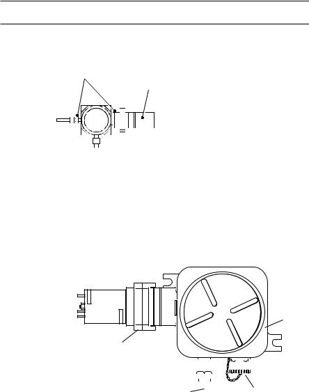
Searchpoint Optima Plus is designed for use in potentially hazardous areas where it provides gas and vapour detection which is free from poisoning and independent of the presence of oxygen. The gas measuring parts of Searchpoint Optima Plus are illustrated below.
Optical Block |
|
Heater |
|
|
|||||||||
|
|
|
|
|
|
|
|
|
|
|
|
|
|
|
|
|
|
|
|
|
|
|
|
|
|
|
|
|
|
|
|
|
|
|
|
|
|
|
|
|
|
|
|
|
|
|
|
|
|
|
|
|
|
|
|
|
|
|
|
|
|
|
|
|
|
|
|
|
|
|
|
|
|
|
|
|
|
|
|
|
|
|
|
|
|
|
|
|
|
|
|
|
|
|
|
|
|
Gas Measuring Path
|
|
|
|
|
|
|
|
|
|
|
|
|
|
|
|
|
|
|
|
|
|
|
|
|
|
|
|
|
|
|
|
|
|
|
|
|
Window |
Heater |
|
Mirror |
||||
|
|
|
|
|
|
|
|
|||||||
|
|
|
|
|
|
|
|
|||||||
|
|
|
|
|
|
|
|
|||||||
Searchpoint Optima Plus uses the dual wavelength infrared absorption principle to detect hydrocarbon gases and vapours in various concentration ranges. The instrument measures the number of molecules of the target gas in the light path, which depends on the concentration of the target gas. In addition to the relatively long and open measuring chamber, Searchpoint Optima Plus can be fitted with a short enclosed flow through-cell as part of the chassis.
This is fitted with separate inlet and outlet ports and allows the application of high concentrations of gas for test purposes.
10
MAN0551 |
Issue 07 - 09/08 |
2108M0501 |
|
1. INTRODUCTION
Searchpoint Optima Plus is a micro-processor controlled, Infrared Gas Detector with comprehensive built-in selfdiagnostic and fault finding facilities. An analogue 4 to
20mA output and digital communications are provided as standard. Full two way communication allows calibration and advanced self checking procedures to be used. To take advantage of these features a Hand-Held Interrogator unit may be connected to a Termination Unit or via the SHC Protection Device to other junction boxes.
There are several different types of termination unit available:
Termination Unit |
Certification |
Output |
|
|
|
DVC Type Termination Units |
|
|
|
|
|
DVC100 (I) MK2 |
ATEX |
Isolated 4-20mA |
|
|
|
DVC100 (M) MK2 |
ATEX |
Isolated 4-20mA and MODBUS |
|
|
|
DX Type Termination Units |
|
|
|
|
|
DVC100 (I) |
UL |
Isolated 4-20mA |
|
|
|
DX100 (M) |
UL |
Isolated 4-20mA and MODBUS |
|
|
|
Searchpoint Optima Plus contains no moving parts and is available in a robust Stainless Steel explosion proof
enclosure which has a M25 (ATEX) or 3/4 NPT (UL and CSA) mounting thread. The unit operates over a wide temperature range and has a high degree of protection against dust
and water ingress. It is designed to operate in the most arduous conditions and is supplied with a choice of weather protection assemblies.
Searchpoint Optima Plus can be In-Duct Mounted, used in Sampling Systems, is easily confidence checked and may easily replace an existing sensor. Provided that
existing cabling has three appropriately rated cores and the installation is correctly screened and earthed, it should not be necessary to replace the field cables or junction boxes. (A current to bridge converter may be required if the controller cannot be configured to accept 4-20mA signals).
11

MAN0551 |
Issue 07 - 09/08 |
2108M0501 |
|
1. INTRODUCTION
No special tools are required for installation. Correct function of the detector as installed can be easily confirmed using a Hand-Held Interrogator. Maintenance amounts to occasional cleaning, zeroing and response checking for confidence.
12
MAN0551 |
Issue 07 - 09/08 |
2108M0501 |
|
|
|
|
|
13

MAN0551 |
Issue 07 - 09/08 |
2108M0501 |
|
2. Installation Variations
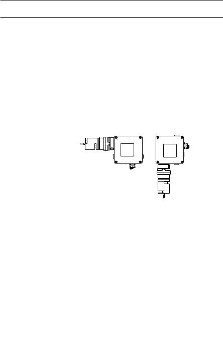
2.1 ATEX Units
Existing Junction Box |
|
Existing Cable |
Optima |
|
Optima
Optima
DVC Termination Unit
SHC-1
Replacing existing Sensor using existing Junction Box and Cable (where suitable).
New Junction Box.
New Installations.
When used for calibration and diagnostics purposes the Hand-Held Interrogator SHC-1 allows digital communication with the Optima. It is connected
to the Optima via the IS Socket on the Termination Unit DVC100 or via the SHC Protection Device for other junction boxes.
14
MAN0551 |
Issue 07 - 09/08 |
2108M0501 |
|
2. Installation Variations
2.2 UL and CSA Units Only
3/4 NPT
Optima
UL and CSA Installations using
Explosion Proof
Junction Box.
Note: The Junction Box must be suitable for the hazardous location in which the Optima is installed, check with the Junction Box manufacturers literature as to suitability of the box.
Top
DX
Termination
Unit
Optima
|
|
|
|
|
|
|
|
|
|
|
|
|
|
|
Handheld |
|
|
|
|
|
|
|
|
|
|
|
|
|
|
|
|
|
|
|
|
|
|
|
|
|
|
|
|
|
|
|
|
|
|
|
|
|
|
|
|
|
|
|
|
|
|
|
|
|
|
|
|
|
|
|
|
|
|
|
|
|
|
|
|
Field |
|
|
|
|
|
|
|
|
|
|
|
|
|
||
Cable / |
|
|
|
|
|
|
|
|
|
|
|
|
|
Interrogator |
|
Conduit |
|
|
|
|
|
|
|
|
|
|
|
|
|
Socket |
|
15
MAN0551 |
Issue 07 - 09/08 |
2108M0501 |
|
|
|
|
|
16

MAN0551 |
Issue 07 - 09/08 |
2108M0501 |
|
3. INSTALLATION
WARNING
The Code of Practice regarding selection, installation and maintenance of electrical apparatus for use in potentially explosive atmospheres must be complied with at all times.
Notes:1. The flying leads of the Searchpoint Optima Plus must be mechanically protected and terminated within a suitable terminal or junction facility.
2.When the detector is terminated in a hazardous area a suitable UL listed enclosure must be used (where appropriate).
3.1UNPACKING
Carefully unpack the equipment, observing any instructions that may be printed on or contained in the packaging, and check the contents for transit damage.
3.2 SITING AND ORIENTATION
Searchpoint Optima Plus must be mounted horizontally, as this greatly reduces the risk of obscuration due to build up of dirt and moisture on the optical surfaces.
Ensure the area immediately surrounding the sensor is free from objects that could hinder the free flow of air around it.
17

MAN0551 |
Issue 07 - 09/08 |
2108M0501 |
|
3. INSTALLATION
For monitoring lighter than air gases, Searchpoint Optima
Plus should be mounted above the area requiring protection.
For monitoring heavier than air gases it should be mounted below the area to be protected.
When monitoring for heavier than air gases and mounting the detector close to the floor, give consideration to the potential of general site debris to build up on the detector.
Whether Searchpoint Optima Plus is installed in a sheltered or an exposed location, it will require some form of protection around the optics. The standard weather protection combined with the sunshade/deluge protection
provides a high degree of protection of the detector, suitable for many outdoor environments. Detectors operating in very exposed locations where torrential rain or driven sea-spray is routinely encountered can benefit from the additional protection provided by the Storm Baffle (2108D0280).
In areas where a high pressure jet may be used at close range to wash down the surrounding location, it is advisable to fit some means of extra peripheral shielding, eg. Storm Baffle or a shield plate.
Accessories and attachments that can be used to improve ease-of-use, performance and reliability in particular installations are described in Section 3.4.
3.3 INSTALLATION guide
Note: Installation of Searchpoint Optima Plus does not require the unit to be opened. There are no user serviceable parts inside the unit. Do not attempt to open or dismantle the unit.
(1)Ensure that the correct attachments and accessories for the application have been fitted (see Section 3.4).
18
MAN0551 |
Issue 07 - 09/08 |
2108M0501 |
|
3.INSTALLATION
(2)Check that the unit's 4-20mA current ouput is of the correct type for the control card that it is connected to.
(Output type is on a label attached to white lead.)
Control card I/P: SINK |
Optima O/P: SOURCE |
Control card I/P: SOURCE |
Optima O/P: SINK |
(3)Secure the junction box onto the mounting surface, using the Junction Box Adaptor Plate if required.
Searchpoint Optima Plus must be installed with it's long axis horizontal in order for the standard weather protection to operate correctly and to prevent water from settling on the optical surfaces (see below).
The Optima unit should therefore only be screwed into a threaded entry that is in a vertical wall of the junction box.
3 |
7 |
(4)Feed the unit's wires carefully through the chosen junction box entry and offer up it's threaded boss to the entry. Screw the unit into the junction box until it is secure and the semi-circular pattern of holes on
the front of the weather protection are on the bottom
(see below). For M25 entries, the boss should go right through the wall and a locking nut should be fitted; whilst for 3/4 NPT entries, the boss should lock off on the taper. If getting the holes in the right orientation requires more rotation than is readily achievable, remove the weather protection and rotate it through 180 degrees.
19

MAN0551 |
Issue 07 - 09/08 |
2108M0501 |
|
3.INSTALLATION
(5)Using a multimeter, check that the voltages on the
+24V, and 4-20mA connections with respect to 0V are less than +32V DC and that there is no 110V or 230V AC around.
(6)Wire up the unit's electrical connections in accordance with Section 4, taking note of the general recommendations upon electrical installation.
(7)Ensure that all cable entries are either used or plugged in strict accordance with the relevant certification requirements and local codes of practice.
(8)Verify the correct installation and operation of the unit using the SHC-1 handheld interrogator. If a Termination Unit has been used, testing can be performed without the need for a hot work permit. Alternatively, if a basic junction box has been used, electrical connections can be made to the terminals inside the box using the SHC adaptor. This will ordinarily require a hot work permit.
CAUTION
1.Searchpoint Optima Plus is certified and specified for operation in ambient temperatures from -40°C to +65°C. Operation of the unit outside of this temperature range invalidates the certification and the warranty. The unit records a non-erasable fault log entry if it is operated at temperatures outside of it's certified range.
If the ambient temperature that the unit could be exposed to is likely to go outside of the certified range it is recommended that the unit be located elsewhere. The use of sampling systems can be highly effective, especially in applications where high temperatures are involved.
20
MAN0551 |
Issue 07 - 09/08 |
2108M0501 |
|
3.INSTALLATION
2.Searchpoint Optima Plus is specified for operation in environments where the rate of change of unit temperature is less than 3°C / minute. Exceeding this rate of change of temperature will cause the unit to report a fault and may cause permanent damage. If the conditions experienced by the unit are likely to cause it to exceed this rate of change it is recommended that additional preventative measures are taken. The use of sampling systems is highly effective; whilst shielding the unit from the prevailing air flow can also be of benefit.
3.Searchpoint Optima Plus has been vibration tested to the levels specified in EN61779. If the vibration levels on the installation exceed this, the unit's reliability and integrity of operation will be degraded. Do not install units in locations where the vibration exceeds this level.
4.All optical gas detectors are eventually affected by the build up of contaminants / condensation upon their optical surfaces, normally resulting in faults or warnings. In order to minimise the faults and warnings caused by this it is recommended that detectors are located as far away as is possible from sources of airborne contaminants and steam / condensation. Alternatively, the fitting of shields or
the Storm Baffle (2108D0280) should be considered.
Sources of contamination / condensation that have caused particular problems where appropriate measures were not taken include generator / turbine exhausts, steam lines / vents, drilling operation
(oilmist and mud spray) and unfiltered HVAC installations. In dusty atmospheres, regularly check for the build up of dust on the detector (refer to section 7 Routine Checks).
21

MAN0551 |
Issue 07 - 09/08 |
2108M0501 |
|
3.INSTALLATION
3.4Attachments And options
3.4.1 General
There are a number of attachments and accessories available for use with Searchpoint Optima Plus. When specifying Optima Plus for a particular application, it is recommended that the user contacts Honeywell Analytics or their representatives to determine the attachments and accessories required. Covers, barriers and baffles provide protection from a wide variety of environmental conditions.
Gassing covers, cells and flow housings provide the means of applying gas to the detector. Mounting plates and remote gassing kits enable the detector to be installed in ducts or in places where obtaining routine access is difficult.
3.4.2 Standard Weather Protection (2108D0276)
Provides the best compromise between response time and protection. Suitable for indoor, outdoor and duct mounting applications.
3.4.3 Sunshade/Deluge Protection (2108D0275)
Supplied as standard for all outside applications. Provides additional protection against heavy rainfall, wash downs and direct sunlight.
22
MAN0551 |
Issue 07 - 09/08 |
2108M0501 |
|
3. INSTALLATION
The Sunshade/ Deluge protection should be clamped around the base of the Standard Baffle
Weather Housing with the longer overhang extending beyond the Standard Baffle.
Ensure the clamp does not cover the gas venting slot of the
Standard Baffle.
3.4.4 Storm Baffle (2108D0280, Not Illustrated)
The storm baffle provides increased protection against a variety of environmental conditions and effects. It is particularly effective against torrential rain and driven sea-spray and is recommended for exposed installations in maritime locations or areas where monsoon or tropical rain conditions are experienced. The storm baffle can be beneficial in installations where steam drifting over the detector from nearby plant is a problem. The storm baffle can also be useful in some duct applications where the
inlets are not filtered and where high flow rates result in dirt build-up or excessive cooling / condensation effects. This accessory will reduce the detector’s speed of response.
3.4.5 Dust Barrier (2108D0259, Not Illustrated)
Fits under the standard baffle weather housing to prevent the ingress of dust or oil mist which could contaminate the optical surfaces. It also protects the optics in very wet or exposed locations. This accessory will reduce the detector’s speed of response.
23

MAN0551 |
Issue 07 - 09/08 |
2108M0501 |
|
3.INSTALLATION
3.4.6Calibration Cap (2108D0272)
Used to achieve accurate calibration of Optima Plus on the bench. Requires all protective covers and attachments to be removed from the measurement chamber except for the
dust barrier. The calibration procedures are described in Section 6.
CAUTION
The Calibration Cap is designed for temporary use on Optima whilst performing calibration. If the calibration cap is left fitted it will prevent ambient gas from reaching the detector's measurement chamber. Ensure that operators are aware that calibration caps must not be left fitted. In order to reduce the likelihood of this mistake going un-noticed, the calibration caps are coloured red.
3.4.7 Gassing Cover (2108D0258)
Provides a convenient means of applying gas to Optima Plus units in the field. Suitable for functional test and calibration purposes. Fits over the standard weather protection, covering the
gas inlet slots. Gas is introduced into the weather protection via an injection tube on the gassing cover. Injected gas diffuses through the dust barrier into the measurement chamber.
The response check procedure is described in Section 5.4.
24

MAN0551 |
Issue 07 - 09/08 |
2108M0501 |
|
3. INSTALLATION
CAUTION
The Gassing Cover is designed for field testing and calibration operations. If the cover is left fitted it will prevent ambient gas from reaching the detector's measurement chamber. Ensure that operators are aware that gassing covers must not be left on detectors. Gassing covers are coloured red to reduce the likelihood of this mistake.
3.4.8 Flow Housing (2108D0282)
For use in sampling system applications.
The Flow Housing is fabricated from solvent resistant Anodised Aluminium.
The nozzles on the Flow Housing are stainless steel with an outside diameter of 6mm.
It is advised that sample gases and vapours are sucked
(negative pressure) rather than blown (positive pressure) through this housing and that sample flow rates do not exceed 2 litres per minute.
It is recommended that a flow failure indicator is fitted within the sampling system and the minimum flow rates are suitable for the application and not less than 0.7 litres per minute.
Note: response time will increase with a decreasing flow rate.
The commissioning and calibration of an Optima equipped with a flow housing is described in Sections 5 and 6.
25

MAN0551 |
Issue 07 - 09/08 |
2108M0501 |
|
3.INSTALLATION
3.4.9Remote Gassing Cell (2108B0240)
The Remote Gassing Cell (RGC) enables high
%V/V concentration gas to be applied remotely for performing functional response checks (bump tests).
It is useful for units installed in ducts or in areas where obtaining access is difficult. The RGC window can be removed for cleaning.
Note:
During production, Optima Plus units are calibrated with gas in the main measurement chamber, not in the RGC. The RGC is not recommended for calibration
or high accuracy calibration testing purposes. (The only exception to this is where units are being
used to measure high %V/V gases using the RGC as a flow cell. In this instance, the units are production calibrated with gas in the RGC.)
In order to avoid pressurisation effects, the flow rate should be kept below 0.3 litres / minute.
The RGC option is factory fitted.
26
MAN0551 |
Issue 07 - 09/08 |
2108M0501 |
|
3.INSTALLATION
3.4.10Junction Box Adaptor Plate (04200-A-1040)
The Junction Box Adaptor Plate provides a means of increasing the spacing between the junction box's gland entries and the mounting surface. This enables low gland clearance junction boxes to be used without the Optima Plus fouling on the wall / mounting surface. Junction boxes which can be accommodated include the Hawke PL612 and PJB1.
27
MAN0551 |
Issue 07 - 09/08 |
2108M0501 |
|
3.INSTALLATION
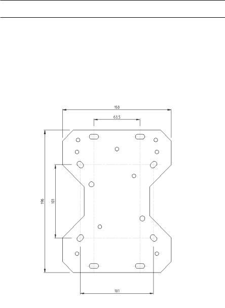
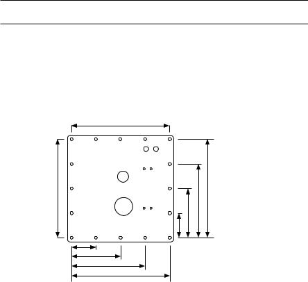
3.4.11European Duct Mounting Kit (04200-A-1015)
This kit enables Optima Plus to be conveniently mounted inside a duct. Electrical connections are made to the detector via a junction box which is mounted outside of the duct. Using this kit, test gas can be non-invasively applied to the detector via the gassing points provided.
250
Note 1: Dimensions shown in mm.
250 |
250 |
|
188 |
|
125 |
|
63 |
63
125
188
250
Note 2: The cutout in the duct should be 230mm x 230mm.
28
MAN0551 |
Issue 07 - 09/08 |
2108M0501 |
|
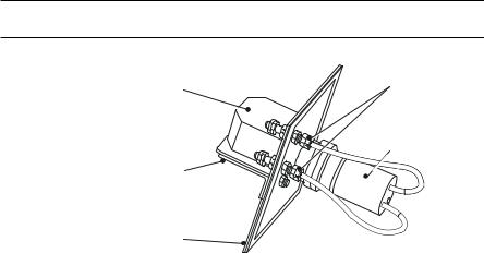
3. INSTALLATION
Gassing
Junction Points
Box
Searchpoint
Optima
Junction
Box
Bracket
Duct
Mounting
Plate
Notes: 1. In order to make use of the gassing points provided, the Optima unit must be fitted with the Remote Gassing Cell (2108B0240).
2.In offshore HVAC ducts or ducts without inlet filtering, the use of the Storm Baffle (2108D0280) is recommended.
3.CSA approval only applies for flow rates less than 5 m/s and does not cover the use of the Storm Baffle.
The duct mounting kit is assembled and installed onto a duct as below:-
(1)Cut a square 230mm * 230mm hole in the duct wall. Drill the holes required to attach the mounting plate to the duct wall.
(2)Place the Optima unit on the side of the mounting plate where the threaded bushes protrude and feed the wires through the central hole.
29

MAN0551 |
Issue 07 - 09/08 |
2108M0501 |
|
3.INSTALLATION
(3)Locate the unit's boss in the central hole and feed the unit's wires through the chosen cable entry on the junction box.
(4)Screw the unit into the junction box until the assembly is secure with the mounting plate trapped between the box and the Optima.
(5)Cut off the seals on the ends of the gassing cell inlet tubes.
(6)Attach the gassing tubing to the ends of the gassing cell inlet tubes.
(7)Fasten the mounting plate to the wall of the duct, ensuring that the seal is compressed.
(8)Wire up the unit in accordance with the electrical connection details in Section 4.
(9)Ensure that all cable entries are either used or plugged in strict accordance with the relevant certification requirements and local codes of practice.
30
 Loading...