


ST 3000 Smart Transmitter |
|
2/08 |
|
||
|
|
|
|
34-ST-03-64 |
|
Series 100 Remote Diaphragm Seals Models |
|
Specification and |
|
||
STR12D |
0-10 to 0-400 inH2O |
0-25 to 0-1000 mbar |
|
|
|
STR14G |
0-5 to 0-500 psig |
0-0.35 to 0-35 bar |
|
Model Selection |
|
STR13D |
0-5 to 0-100 psid |
0-0.35 to 0-7 bar |
|
|
|
STR17G |
0-100 to 0-3000 psig |
0-7 to 0-210 bar |
|
Guide |
|
STR14A |
0-5 to 0-500 psia |
0-0.35 to 0-35 bar |
|
|
|
|
|
|
|
|
|
Introduction
In 1983, Honeywell introduced the first Smart Pressure Transmitter― the ST 3000®. In 1989, Honeywell launched the first all digital, bi-directional protocol for smart field devices. Today, its ST 3000 Series 100 Remote Seal Transmitters continue to bring proven “smart” technology to a wide spectrum of measurement applications. Typical applications include high accuracy level measurement in pressurized vessels in the chemical and hydrocarbon processing industries. A second application consists of accurate flow measurement for slurries and high viscosity fluids in the chemical industry. Honeywell remote seal transmitters demonstrate proven reliability in hundreds on installations in a wide variety of industries and applications with a wide variety of secondary fill fluids for corrosive or high temperature process fluids.
All ST 3000 transmitters can provide a 4-20 mA output, Honeywell Digitally Enhanced (DE) output, HART* output, or FOUNDATION™ Fieldbus output. When digitally integrated with Honeywell’s Process Knowledge System™, EXPERION PKS™,
ST 3000 instruments provide a more accurate process variable as well as advanced diagnostics.
Honeywell’s high-performance ST 3000 S100 transmitters lead the industry in:
•Accuracy
•Stability
•Reliability
•Rangeability
•Warranty
Includes Lifetime™ Transmitters:
•Total Accuracy = ±0.0375%
•Stability = ±0.01% per year
•Reliability = 470 years MTBF
•Rangeability = 400 to 1
•Lifetime Warranty = 15 years
Figure 1—Series 100 Remote Seal Pressure Transmitters feature proven piezoresistive sensors and advanced seal technology with standard weld connections.
The devices provide comprehensive self-diagnostics to help users maintain high uptime, meet regulatory requirements, and attain high quality standards. S100 transmitters are ideal for critical applications, such as custody transfer of natural gas and energy and material balances, where accuracy and stability are of the utmost importance.
"Our commitment to Honeywell field instruments is based on seamless integration with our Honeywell system and the enhanced fault detection that the Honeywell DE protocol offers. Honeywell instruments also offer us a better way of ensuring database integrity over simple analog instruments. In addition, Honeywell's high-quality support has enabled us to better implement solutions to some of our more difficult problems. We have used Honeywell differential pressure smart transmitters for the past eight years. Based on their accuracy and low failure rates, we are now targeting critical flow applications that require the robustness that these transmitters bring.”
DCS Systems Engineer International Integrated Oil Company
34-ST-03-64
Page 2
Description of Diaphragm Seals
Diaphragm seals are traditionally used when a standard pressure transmitter should not be exposed to the process pressure directly. Diaphragm seals typically protect the pressure transmitter from one or more damaging aspects of the process media. Consideration for using a diaphragm seal should be made in the following circumstances.
•High Process Temperature
•Process Media is Viscous or Contains Suspended Solids
•Process Media is Subject to Solidifying
•Process Media is Corrosive
•Process Application Requires Sanitary Connections
•Process Application Subjects the Measuring Instrument to Hydrogen Permeation
•Tank Level Applications with Maintenance Intensive Wet Legs
•Tank Application with Density or Interface Measurements
•Measuring Instrument Requires Remote Mounting
The following diaphragm seals are standard from Honeywell (please call your local salesperson if you do not see the product you need for your application):
Figure 2 - Flush Flange Seals can be used with differential, gauge and absolute pressure transmitters and are available with 3” ANSI Class 150, ANSI Class 300 and DIN DN80-PN40 process connections. Flush flange seals can also be provided with Lowers. Lowers are essentially calibration rings, which allow flushing connections if needed – see Figure 31.
Figure 2
Figure 3 - Flange Seal with Extended Diaphragm can be used with differential, gauge and absolute pressure transmitters and are available with 3” and 4” ANSI Class 150, ANSI Class 300, DIN DN80-PN40 and DIN DN100-PN40 process connections. 2”, 4” and 6” extension lengths are available.
Figure 3
Figure 4 - Pancake Seals can be used with differential, gauge and absolute pressure transmitters and are available with 3” ANSI Class 150, 300 and 600 process connections.
Figure 4
Figure 5 - Chemical Tee “Taylor” Wedge seals can be used with differential pressure transmitters and are available with Taylor Wedge 5” O.D. process connection.
Figure 5
34-ST-03-64
Page 3
Description of Diaphragm Seals
Figure 6 - Seals with Threaded Process Connections can be used with differential, gauge and absolute pressure transmitters and are available with ½”, ¾” and 1” NPT Female process connections.
Figure 6
Figure 7 - Sanitary Seals can be used with differential, gauge and absolute pressure transmitters and are available with 3” and 4” Tri-Clover-Tri-Clamp process connections.
Figure 7
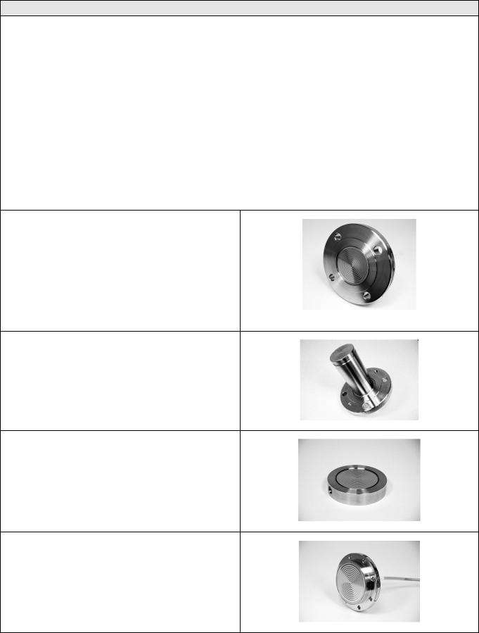
Figure 8 - Saddle Seals can be used with differential, gauge and absolute pressure transmitters and are available with 3” and 4” (6 bolt or 8 bolt designs) process connections.
Figure 8
Figure 9 - Calibration Rings are available with Flush Flange Seals and Pancake Seals. Flushing ports (1/4” or ½”) are available with calibration rings.
Figure 9
Figure 10 - Stainless Steel Armor and PVC Coated
Stainless Steel Armor Capillaries are available with
Honeywell Remote Seal Solutions.
Figure 10
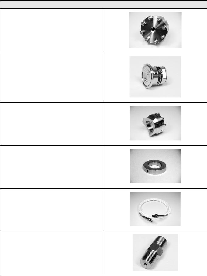
Figure 11 - 2” Stainless Steel Nipples are available for Close-Coupled remote seal solutions.
Figure 11
34-ST-03-64
Page 4
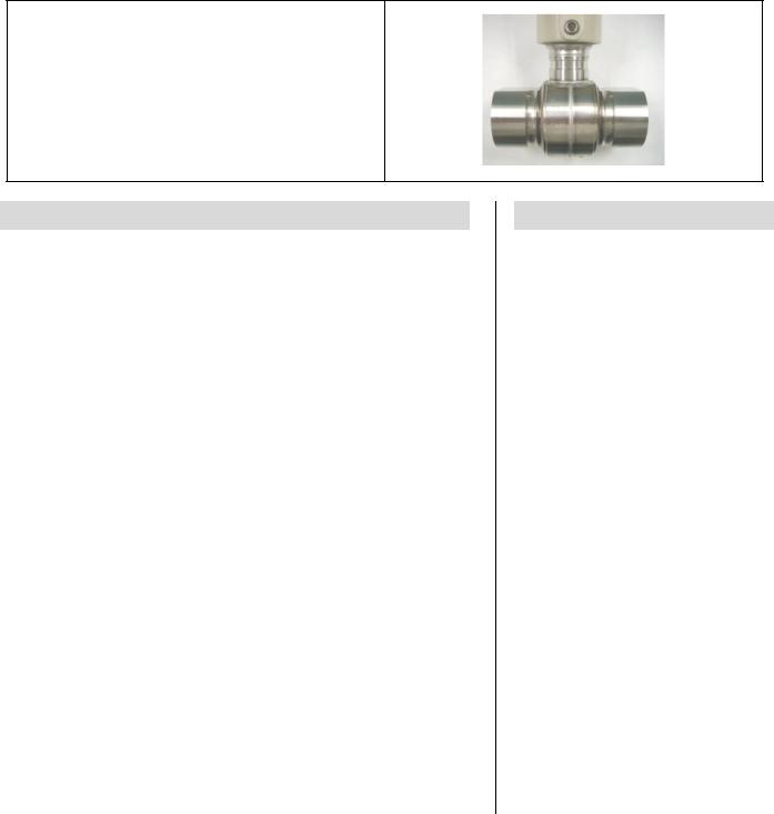
Figure 12 - Welded Meter Body for All-Welded Remote Seal Solution. The welded ST 3000 meter body is an important part of an All-Welded Remote Seal Solution, which is commonly used in Vacuum applications.
Figure 12
Description
The ST 3000 transmitter can replace any 4 to 20 mA output transmitter in use today and operates over a standard two-wire system.
The measuring means is a piezoresistive sensor, which actually contains three sensors in one. It contains a differential pressure sensor, a temperature sensor, and a static pressure sensor.
Microprocessor-based electronics provide higher span-turndown ratio, improved temperature and pressure compensation, and improved accuracy.
The transmitter’s meter body and electronics housing resist shock, vibration, corrosion, and moisture. The electronics housing contains a compartment for the single-board electronics, which is isolated from an integral junction box. The single-board electronics is replaceable and interchangeable with any other ST 3000 Series 100 or Series 900 model transmitter.
Like other Honeywell transmitters, the ST 3000 features two-way communication and configuration capability between the operator and the transmitter through several Honeywell field-rated portable configuration devices, including the Smart Field Communicator (SFC) and the Multiple Communication Configurator (MC ToolKit). While both are made for in-field use, the MC Toolkit also can be ordered for use in intrinsically safe environments.
The SCT 3000 Smartline® Configuration Toolkit provides an easy way to configure instruments using a personal computer. The toolkit enables configuration of devices before shipping or installation. The SCT 3000 can operate in the offline mode to configure an unlimited number of devices. The database can then be loaded down-line during commissioning.
Features
•Choice of linear or square root output conformity is a simple configuration selection.
•Direct digital integration with Experion PKS and other control systems provides local measurement accuracy to the system level without adding typical A/D and D/A converter inaccuracies.
•Unique piezoresistive sensor automatically compensates input for temperature and static pressure. Added “smart” features include configuring lower and upper range values, simulating accurate analog output, and selecting preprogrammed engineering units for display.
•Smart transmitter capabilities with local or remote interfacing means significant manpower efficiency improvements in commissioning, start-up, and ongoing maintenance functions.

|
|
|
|
|
|
|
|
|
|
|
|
|
34-ST-03-64 |
||
|
|
|
|
|
|
|
|
|
|
|
|
|
|
Page 5 |
|
|
|
|
|
|
|
|
|
|
|
|
|
|
|
|
|
|
|
|
|
|
Specifications |
|
|
|
|
|
|
||||
|
Operating Conditions – All Models |
|
|
|
|
|
|
|
|
|
|
||||
|
Parameter |
|
Reference Condition |
Rated Condition |
|
Operative Limits |
Transportation and |
|
|||||||
|
|
|
|
|
|
|
|
|
|
|
|
|
Storage |
|
|
|
|
|
|
|
|
|
|
|
|
|
|
|
|
|
|
|
|
|
°C |
|
°F |
°C |
|
°F |
|
°C |
|
°F |
°C |
°F |
|
|
|
|
|
|
|
|
|
|
|
|
|
|
|
|
|
|
Ambient Temperature * |
25 ±1 |
|
77 ±2 |
— |
|
— |
|
— |
|
— |
–55 to 90 |
–67 to 194 |
|
|
|
Humidity |
% RH |
10 to 55 |
|
0 to 100 |
|
0 to 100 |
|
0 to 100 |
|
|||||
|
|
|
|
|
|
|
|
||||||||
|
Maximum Allowable |
|
MAWP is minimum of Body Rating or Seal Rating (See Model Selection Guide for Seal |
|
|||||||||||
|
Working Pressure (MAWP) |
MAWP) |
|
|
|
|
|
|
|
|
|
|
|
|
|
|
|
|
|
Body |
|
MAWP |
|
|
|
|
|
|
|||
|
|
|
|
STR12D |
|
2500 psig (172 bar) Bolted Process Heads Table I _ _ A |
|
||||||||
|
|
|
|
STR13D |
|
2500 psig (172 bar) Bolted Process Heads Table I _ _ A |
|
||||||||
|
|
|
|
STR12D |
|
1450 psig (100 bar) All Welded Process Heads Table I _ _ C |
|
||||||||
|
|
|
|
STR13D |
|
1450 psig (100 bar) All Welded Process Heads Table I _ _ C |
|
||||||||
|
|
|
|
STR14G |
|
500 psig (35 bar) |
|
|
|
|
|
|
|||
|
|
|
|
STR17G |
|
3000psig (207 bar) |
|
|
|
|
|||||
|
|
|
|
STR14A |
|
500 psia (35 bar). |
|
|
|
|
|
|
|||
|
Vacuum Region - Minimum |
|
|
|
|
|
|
|
|
|
|
|
|
|
|
|
Pressure |
|
|
|
|
|
|
|
|
|
|
|
|
|
|
|
mmHg absolute |
|
Atmospheric (See Figure 15 for vacuum limitations.) |
|
|
|
|
||||||||
|
|
|
|
|
|
|
|
||||||||
|
Supply Voltage, Current, |
Voltage Range: |
10.8 to 42.4 Vdc at terminals |
|
|
|
|
||||||||
|
and Load Resistance |
|
Current Range: |
3.0 to 21.8 mA |
|
|
|
|
|
|
|||||
|
|
|
Load Resistance: |
0 to 1440 ohms (as shown in Figure 16) |
|
|
|
||||||||
|
|
|
|
|
|
|
|
|
|
|
|
|
|
|
|
* Ambient Temperature Limit is a function of Process Interface Temperature. (See Figure 13.)

34-ST-03-64
Page 6
Performance Under Rated Conditions * - Model STR12D (0-10 to 0-400 inH2O)
Parameter |
|
|
|
|
|
|
|
|
|
Description |
|
|
|
||||||
Upper Range Limit ** |
inH2O |
400 (39.2°F/4°C is standard reference temperature for inH2O range.) |
|||||||||||||||||
|
mbar |
1000 |
|
|
|
|
|
|
|
|
|
|
|
|
|
|
|
|
|
|
|
|
|
|
|
|
|
|
|
|
|
|
|||||||
Minimum Span |
inH2O |
10 Note: Recommended minimum span in square root mode is 20 inH2O (50 mbar). |
|||||||||||||||||
|
mbar |
25 |
|
|
|
|
|
|
|
|
|
|
|
|
|
|
|
|
|
|
|
|
|
|
|
|
|
|
|
|
|
|
|
|
|
|
|
|
|
Turndown Ratio |
|
40 to 1 |
|
|
|
|
|
|
|
|
|
|
|
|
|
|
|
|
|
|
|
|
|
|
|
|
|
|
|
|
|
|
|
||||||
Zero Elevation and Suppression |
No limit except minimum span within ±100% URL. |
|
|
|
|||||||||||||||
|
|
|
|
||||||||||||||||
Accuracy (Reference – Includes |
In Analog Mode: ±0.2% of calibrated span or upper range value (URV), whichever is |
||||||||||||||||||
combined effects of linearity, |
greater, terminal based. |
|
|
|
|
|
|
|
|
|
|
|
|||||||
hysteresis, and repeatability) |
For URV below reference point (50 inH2O), accuracy equals: |
||||||||||||||||||
|
|
||||||||||||||||||
• Accuracy includes residual error |
±0.1 + 0.1 |
50 inH2O |
or ±0.1 + 0.1 |
|
125 mbar |
in % of span |
|||||||||||||
after averaging successive |
|
||||||||||||||||||
|
|
|
|
|
|
|
|
|
|
||||||||||
span inH2O |
(span mbar) |
||||||||||||||||||
readings. |
|
|
|
|
|
|
|
|
|||||||||||
• For FOUNDATION Fieldbus use |
In Digital Mode: ±0.175% of calibrated span or upper range value (URV), whichever is |
||||||||||||||||||
Digital Mode specifications. For |
greater, terminal based. |
|
|
|
|
|
|
|
|
|
|
|
|||||||
HART use Analog Mode |
|
For URV below reference point (50 inH2O), accuracy equals: |
|||||||||||||||||
specifications. |
|
|
|
|
50 inH2O |
|
|
|
|
|
125 mbar |
||||||||
|
|
|
|
|
|
|
|
|
|||||||||||
|
|
±0.075 + 0.10 |
|
|
or ±0.075 + 0.10 ( |
|
) in % of span |
||||||||||||
|
|
span inH2O |
span mbar |
||||||||||||||||
Combined Zero and Span |
In Analog Mode: ±1.2% of span. |
|
|
|
|
|
|
|
|
||||||||||
Temperature Effect per 28°C |
For URV below reference point (200 inH2O), effect equals: |
||||||||||||||||||
(50°F) *** |
|
||||||||||||||||||
|
|
±0.2 + 1.0 |
200 in H2O |
|
or ±0.2 + 1.0 |
|
500 mbar |
In % span |
|||||||||||
|
|
|
|
|
|
|
|
|
|
|
|
|
|||||||
|
|
span in H2O |
|
|
span mbar |
||||||||||||||
|
|
|
|
|
|
|
|
||||||||||||
In Digital Mode: ±1.175% of span.
For URV below reference point (200 inH2O), effect equals:
|
|
200 in H2O |
|
|
500 mbar |
|
±0.175 + 1.0 |
|
|
or ±0.175 + 1.0 |
|
span mbar |
In % span |
span in H2O |
*Performance specifications are based on reference conditions of 25°C (77°F), zero (0) static pressure, 10 to 55% RH, and 316L Stainless Steel barrier diaphragm.
**Transmitter URL limit or maximum seal pressure rating, whichever is lower.
***Specification applies to transmitters with 2 seals only. Apply 1.5 times factor to temperature effect for capillary lengths greater than 10 feet.

34-ST-03-64
Page 7
Performance Under Rated Conditions * - Model STR13D (0-5 to 0-100 psid)
Parameter
Upper Range Limit ** |
psid |
|
bar |
|
|
Minimum Span |
psid |
|
bar |
|
|
Turndown Ratio |
|
Zero Elevation and Suppression
Accuracy (Reference – Includes combined effects of linearity, hysteresis, and repeatability)
•Stated accuracy does not apply for models with 2.9 inch diameter remote seal diaphragms.
•Accuracy includes residual error after averaging successive readings.
•For FOUNDATION Fieldbus use Digital Mode specifications. For HART use Analog Mode specifications.
Combined Zero and Span Temperature Effect per 28°C (50°F) ***
Description
100
7
5
0.35
20 to 1
No limit except minimum span within –18% and +100% of URL. Specifications valid from –5% to 100% of URL.
In Analog Mode: ±0.1% of calibrated span or upper range value (URV), whichever is greater, terminal based.
For URV below reference point (30 psi), accuracy equals:
|
30 psi |
|
2 bar |
||
±0.05 + 0.05 ( |
|
) or |
±0.05 + 0.05 ( |
|
) in % of span |
span psi |
span bar |
||||
In Digital Mode: ±0.075% of calibrated span or upper range value (URV), whichever is greater, terminal based.
For URV below reference point (30 psi), accuracy equals:
|
30 psi |
|
2 bar |
||
±0.025 + 0.05 ( |
|
) or ±0.025 + 0.05 |
( |
|
) in % of span |
span psi |
span bar |
||||
In Analog Mode: ±0.33% of span.
For URV below reference point (60 psi), effect equals:
|
|
60 psi |
|
|
4 bar |
|
±0.05 + 0.2 |
|
span psi |
or ±0.05 + 0.28 |
|
span bar |
In % span |
In Digital Mode: ±0.305% of span.
For URV below reference point (60 psi), effect equals:
|
|
60 psi |
|
|
4 bar |
|
±0.025 + 0.25 |
|
span psi |
or ±0.025 + 0.28 |
|
span bar |
In % span |
*Performance specifications are based on reference conditions of 25°C (77°F), zero (0) static pressure, 10 to 55% RH, and 316L Stainless Steel barrier diaphragm.
**Transmitter URL limit or maximum seal pressure rating, whichever is lower.
***Specification applies to transmitters with 2 seals only. Apply 1.5 times factor to temperature effect for capillary lengths greater than 10 feet.
34-ST-03-64
Page 8
Performance Under Rated Conditions * - Model STR14G (0-5 to 0-500 psig)
|
Parameter |
|
|
|
|
|
|
|
Description |
||||
|
Upper Range Limit ** |
psig |
500 |
|
|
|
|
|
|
|
|
|
|
|
|
bar |
35 |
|
|
|
|
|
|
|
|
|
|
|
|
|
|
|
|
|
|
|
|
|
|
|
|
|
Minimum Span |
psig |
5 |
|
|
|
|
|
|
|
|
|
|
|
|
bar |
0.35 |
|
|
|
|
|
|
|
|
|
|
|
|
|
|
|
|
|
|
|
|
|
|
|
|
|
Turndown Ratio |
|
|
100 to 1 |
|
|
|
|
|
||||
|
|
|
|
|
|
|
|
|
|
|
|
||
|
Zero Elevation and Suppression |
|
No limit except minimum span from absolute zero to 100% of URL. Specifications valid |
||||||||||
|
|
|
|
over this range. |
|
|
|
|
|
||||
|
|
|
|
||||||||||
|
Accuracy (Reference – Includes |
|
In Analog Mode: ±0.1% of calibrated span or upper range value (URV), whichever is |
||||||||||
|
combined effects of linearity, |
|
|
greater. |
|
|
|
|
|
||||
|
hysteresis, and repeatability) |
|
|
For URV below reference point (20 psi), accuracy equals: |
|||||||||
|
|
|
|
||||||||||
|
• Accuracy includes residual error |
|
|
|
20 psi |
|
1.4 bar |
||||||
|
after averaging successive |
|
|
±0.05 + 0.05 ( |
|
|
) or |
±0.05 + 0.05 ( |
|
|
) in % of span |
||
|
|
|
span psi |
span bar |
|||||||||
|
readings. |
|
|
In Digital Mode: ±0.075% of calibrated span or upper range value (URV), whichever is |
|||||||||
|
• For FOUNDATION Fieldbus use |
|
|||||||||||
|
|
greater. |
|
|
|
|
|
||||||
|
Digital Mode specifications. For |
|
|
|
|
|
|
||||||
|
|
For URV below reference point (20 psi), accuracy equals: |
|||||||||||
|
HART use Analog Mode |
|
|
||||||||||
|
specifications. |
|
|
|
|
20 psi |
|
|
1.4 bar |
||||
|
|
|
|
±0.025 + 0.05 ( |
|
) or |
±0.025 + 0.05 ( |
|
) in % of span |
||||
|
|
|
|
span psi |
span bar |
||||||||
*Performance specifications are based on reference conditions of 25°C (77°F), zero (0) static pressure, 10 to 55% RH, and 316L Stainless Steel barrier diaphragm.
**Transmitter URL limit or maximum seal pressure rating, whichever is lower.

34-ST-03-64
Page 9
Performance Under Rated Conditions * - Model STR17G (0-100 to 0-3000 psig)
Parameter
Upper Range Limit ** |
psig |
|
bar |
|
|
Minimum Span |
psig |
|
bar |
|
|
Turndown Ratio |
|
Zero Elevation and Suppression
Accuracy (Reference – Includes combined effects of linearity, hysteresis, and repeatability)
•Accuracy includes residual error after averaging successive readings.
•For FOUNDATION Fieldbus use Digital Mode specifications. For HART use Analog Mode specifications.
Description
3000
210
100
7
30 to 1
No limit except minimum span from absolute zero to 100% of URL. Specifications valid over this range.
In Analog Mode: ±0.15% of calibrated span or upper range value (URV), whichever is greater.
For URV below reference point (300 psi), accuracy equals:
|
300 psi |
|
21 bar |
||
±0.10 + 0.05 ( |
|
) or ±0.10 + 0.05 |
( |
|
) in % of span |
span psi |
span bar |
||||
In Digital Mode: ±0.125% of calibrated span or upper range value (URV), whichever is greater.
For URV below reference point (300 psi), accuracy equals:
|
300 psi |
|
21 bar |
||
±0.075 + 0.05 ( |
|
) or |
±0.075 + 0.05 ( |
|
) in % of span |
span psi |
span bar |
||||
*Performance specifications are based on reference conditions of 25°C (77°F), zero (0) static pressure, 10 to 55% RH, and 316L Stainless Steel barrier diaphragm.
**Transmitter URL limit or maximum seal pressure rating, whichever is lower.
34-ST-03-64
Page 10
Performance Under Rated Conditions * - Model STR14A (0-5 to 0-500 psia)
|
Parameter |
|
|
|
|
|
|
|
Description |
||||
|
Upper Range Limit ** |
psia |
500 |
|
|
|
|
|
|
|
|
|
|
|
bar absolute |
35 |
|
|
|
|
|
|
|
|
|
||
|
|
|
|
|
|
|
|
|
|
|
|
|
|
|
Minimum Span |
psia |
5 |
|
|
|
|
|
|
|
|
|
|
|
bar absolute |
0.35 |
|
|
|
|
|
|
|
|
|
||
|
|
|
|
|
|
|
|
|
|
|
|
|
|
|
Turndown Ratio |
|
|
100 to 1 |
|
|
|
|
|
||||
|
|
|
|
|
|
|
|
|
|
|
|
||
|
Zero Elevation and Suppression |
|
No limit except minimum span from 0 to 100% URL. |
||||||||||
|
|
|
|
||||||||||
|
Accuracy (Reference – Includes |
|
In Analog Mode: ±0.1% of calibrated span or upper range value (URV), whichever is |
||||||||||
|
combined effects of linearity, |
|
|
greater. |
|
|
|
|
|
||||
|
hysteresis, and repeatability) |
|
|
For URV below reference point (20 psi), accuracy equals: |
|||||||||
|
|
|
|
||||||||||
|
• Accuracy includes residual error |
|
|
|
20 psi |
|
1.4 bar |
||||||
|
after averaging successive |
|
|
±0.05 + 0.05 ( |
|
|
) or |
±0.05 + 0.05 ( |
|
|
) in % of span |
||
|
|
|
span psi |
span bar |
|||||||||
|
readings. |
|
|
In Digital Mode: ±0.075% of calibrated span or upper range value (URV), whichever is |
|||||||||
|
• For FOUNDATION Fieldbus use |
|
|||||||||||
|
|
greater. |
|
|
|
|
|
||||||
|
Digital Mode specifications. For |
|
|
|
|
|
|
||||||
|
|
For URV below reference point (20 psi), accuracy equals: |
|||||||||||
|
HART use Analog Mode |
|
|
||||||||||
|
specifications. |
|
|
|
|
20 psi |
|
|
1.4 bar |
||||
|
|
|
|
±0.025 + 0.05 ( |
|
) or |
±0.025 + 0.05 ( |
|
) in % of span |
||||
|
|
|
|
span psi |
span bar |
||||||||
*Performance specifications are based on reference conditions of 25°C (77°F), zero (0) static pressure, 10 to 55% RH, and 316L Stainless Steel barrier diaphragm.
**Transmitter URL limit or maximum seal pressure rating, whichever is lower.
Performance Under Rated Conditions – General for all Models
Parameter |
Description |
Output (two-wire) |
Analog 4 to 20 mA or digital communications DE mode. Options available for |
|
FOUNDATION Fieldbus and HART protocol. |
|
|
Supply Voltage Effect |
±0.005% of span per volt. |
|
|
Damping Time Constant |
Adjustable from 0 to 32 seconds digital damping. |
|
|
RFI Protection (Standard) |
Negligible (20 to 1000 MHz at 30 volts per meter). |
|
|
CE Conformity (Europe) |
89/336/EEC, Electromagnetic Compatibility (EMC) Directive. |
|
|
NAMUR NE 43 Compliance |
Transmitter failure information is generated when the measuring information is invalid or |
Option |
no longer present. Failure information is transmitted as a current signal but outside the |
|
normal 4-20 mA measurement signal level. Transmitter failure values are: ≤ 3.6 mA and |
|
≥ 21.0 mA. The normal signal range is ≥ 3.8 mA and ≤ 20.5 mA. |
|
|
SIL 2/3 Compliance |
SIL certified to IEC 61508 for non-redundant use in SIL 2 related Safety Systems |
|
(single use) and for redundant (multiple) use in SIL 3 Safety Systems through |
|
TÜV Nord Sys Tec GmbH & Co. KG under the following standards: IEC61508-1: 1998; |
|
IEC 61508-2: 2000; IEC61508-3: 1998. |

34-ST-03-64
Page 11
Physical and Approval Bodies
Parameter
Process Interface
Seal Barrier Diaphragm
Seal Gasket Materials
Mounting Bracket
Fill Fluid (Meter Body)
Fill Fluid (Secondary)
Electronic Housing
Capillary Tubing
Wiring
Mounting
Dimensions
Net Weight
Approval Bodies
Factory Mutual
CSA
Canadian Registration
Number (CRN)
ATEX
SA (Australian)
INMETRO (Brazil)
Description
See Model Selection Guide for Material Options for desired seal type.
316L Stainless Steel, Monel, Hastelloy C, Tantalum
Klinger C-4401 (non-asbestos) |
Grafoil |
Teflon |
Gylon 3510 |
Carbon Steel (Zinc-Chromate plated) or Stainless Steel.
Silicone (DC 200) |
S.G. @ 25°C = 0.94 |
CTFE (Chlorotrifluoroethylene) |
S.G. @ 25°C = 1.89 |
Silicone (DC 200) |
S.G. @ 25°C = 0.94 |
CTFE (Chlorotrifluoroethylene) |
S.G. @ 25°C = 1.89 |
Silicone (DC 704) |
S.G. @ 25°C = 1.07 |
NEOBEE M-20 |
S.G. @ 25°C = 0.90 |
Syltherm 800 |
S.G. @ 25°C = 0.93 |
Epoxy-Polyester hybrid paint. Low copper-aluminum alloy. Meets NEMA 4X (watertight) and NEMA 7 (explosion proof). Stainless steel optional.
Armored Stainless Steel or PVC Coated Armored Stainless Steel.
Length: 5, 10, 15, 20, 25, and 35 feet (1.5, 3, 4.6, 6.1, 7.5, and 10.7 meters).
A 2 inch (51 millimeter) S.S. close-coupled nipple is also available. See Model Selection Guide. Refer to Figure 14 for guide to maximum capillary length vs. diaphragm diameter.
Accepts up to 16 AWG (1.5 mm diameter).
See Figure 17.
Transmitter: See Figures 20a and 20b. Seal: See Figures 21 through 31.
Transmitter: 15.4 pounds (7 Kg). Total weight is dependent on seal type and capillary length.
Explosion Proof: Approved as Explosion Proof for Class I, Division 1, Groups A, B, C, D locations,
Dust Ignition Proof: Approved as Dust Ignition Proof for Class II, III, Division 1, Groups E, F, G locations,
Intrincically Safe: Approved as Intrinsically Safe for for Class I, II, III, Division 1, Groups A, B, C, D, E, F, G locations.
Nonincendive: Approved as Nonincendive for Class I, Division 2, Groups A, B, C, D locations.
Explosion Proof: Approved as Explosion Proof for Class I, Division 1, Groups B, C, D locations,
Dust Ignition Proof: Approved as Dust Ignition Proof for Class II, III, Division 1, Groups E, F, G locations,
Intrincically Safe: Approved as Intrinsically Safe for Class I, II, III, Division 1, Groups A, B, C, D, E, F, G locations.
All ST 3000 model designs, except SATG19L, STG99L, STG170 and STG180 have been registered in all provinces and territories in Canada and are marked CRN:0F8914.5c.
Intrinsically Safe, Zone 0/1: EEx ia IIC T4, T5, T6
Flameproof/Zone 1: |
|
EEx d IIC T5, T6 (enclosure IP 66/67) |
Non-Sparking, Zone 2: |
EEx nA, IIC T6 (enclosure IP 66/67) |
|
Multiple Markings: |
|
Ex II 1 G: EEx ia IIC T4, T5, T6, Ex II 2 G: EExd IIC T5, T6 |
|
|
Ex II 3 G: EEx nA, IIC T6 (Honeywell) (enclosure IP 66/67) |
Intrinsically Safe: |
EX ia IIC T4 |
|
Non-Sparking: |
Ex n IIC T6 (T4 with SM option) |
|
Flame-Proof, Zone 1: |
EX d IIC T5 |
|
 Loading...