


 Loading...
R7284B,P,U,G
Electronic Oil Primary,
EnviraCOM™ Enabled
|
INSTALLATION INSTRUCTIONS |
APPLICATION |
configure device parameters, retrieve diagnostic |
|
The advanced interface has a two-line display used to |
The R7284B,P,U,G Electronic Oil Primary is a line |
information, and display system status. |
|
|
voltage, safety rated, interrupted and intermittent ignition |
The basic interface has a single LED used to display |
oil primary control for residential oil fired burners used in |
error codes and system status. |
boilers, forced air furnaces and water heaters. The |
In general, the “i” button cycles through the display |
R7284B,P,U,G used with a cad cell flame sensor |
|
operates an oil burner, spark igniter, and optional oil |
options and acts as an “enter” key (in setup modes). |
valve. The control works with a low voltage and optional |
|
high voltage thermostat. The primary controls fuel oil, |
Thermostat(s) |
senses flame, controls ignition spark (either interrupted |
|
or intermittent) and notifies through the EnviraCOM™ |
The oil primaries are compatible with both standard |
bus a remote alarm circuit when in lockout. |
thermostats and EnviraCOM™ communicating |
The R7284 Series of Oil Primary Controls can be used |
thermostats. |
|
|
with both hydronic and forced air systems. When used |
Limited Recycle |
with hydronic systems, line voltage switching Aquastat® |
|
Controllers normally provide for the starting and stopping |
This feature limits the number of recycle trials (for each |
of the combustion sequences. With forced air systems, |
call for heat) to a maximum of three trials. If the flame is |
both mechanical and electronic low voltage thermostats |
lost three times and does not successfully satisfy a call |
control the starting and stopping of the combustion |
for heat, the R7284 locks out. |
process. |
|
Some hydronic and forced air systems require a delayed valve-on and burner motor-off delay. The R7284 operates an oil valve that prevents the flow of oil when the burner motor is running prior to combustion (delayed valve-on) and when the burner motor is running after combustion (burner motor-off delay).
The R7284 models are intended for use only on oil burning appliances which do not require prepurge and post-purge as a safety related function as defined in UL296. The valve-on delay and burner motor-off delay in this control are intended only to help establish draft and reduce oil after-drip related problems.
EnviraCOM™ enabled R7284’s can be used with EnviraLink® remote monitoring systems and hand-held diagnostics. Use only R7284P and U models for networking with other EnviraCOM™ enabled devices.
FEATURES
User Interface
There are two user interfaces: basic and advanced. Both interfaces consist of three buttons: , , and “i.”
Pump Priming Cycle
To facilitate purging air from the oil lines and filters, the R7284 can be placed in a purge routine by pressing and releasing the up arrow button during the Trial For Ignition.
In the advanced interface “PUMP PRIME” is displayed on the display along with the time left on the Trial for Ignition (TFI). Pressing the up arrow button adds a minute to the TFI time for a maximum of 10 additional minutes (press the up arrow button 10 times). Pressing the down arrow button subtracts a minute from the TFI time.
There is no visual indication for the basic interface control and the purge timing is limited to five minutes.
Disable Function
Pressing and holding the “i” button will disable all control functions until 3 seconds after the button is released.
Lockout Modes
The R7284 has three types of lockout modes that are entered when an error is encountered:
69-2467EFS-05
R7284B,P,U,G ELECTRONIC OIL PRIMARY, ENVIRACOM™ ENABLED
• Soft Lockout: Caused by a temporary internal error |
NOTE: |
Some models have adjustable Valve-on Delay, |
||||
such as low voltage. The control recovers |
|
Burner Off Delay, and Lockout timings. |
||||
automatically after the error is no longer detected. |
Electrical Ratings: |
|||||
• Hard Lockout: Caused by a failure internal to the |
||||||
control or by a system fault such as flame out of |
Inputs: |
|
||||
sequence. A Hard Lockout will result in a no heat |
Voltage: 102 to 132 Vac, 120 Vac nominal. |
|||||
condition. To reset from Hard Lockout press and hold |
Current: 0.5A plus burner motor, valve and igniter |
|||||
the “i” button for 2 seconds. |
|
loads. |
||||
• Restricted Lockout: Caused by a number of |
Frequency: 60 Hz. |
|||||
consecutive hard lockouts on the same heat cycle. To |
Outputs: |
|
||||
reset from a Restricted Lockout press and hold the “i” |
Relay Contacts: |
|||||
button for ten seconds. |
|
|
Burner: 120 Vac, 10 full load amperes (FLA), 60 locked |
|||
|
|
|
|
rotor amperes (LRA). |
||
Cad Cell Resistance |
|
Valve: 120 Vac, 1A. |
||||
|
Igniter: 120 Vac, 3 A. |
|||||
Cad cell resistance can be checked without using an ohm |
Low Voltage Shutdown: 80 Vac |
|||||
meter. |
|
|
|
Thermostat Current Available: 100 mA. |
||
Basic Interface: |
|
|
EnviraCOM™ Current Available: 150 mA. |
|||
|
|
NOTE: |
Reduce burner FLA rating by igniter load. For |
|||
Press and release the “i” button. The resulting flashes |
||||||
indicate the resistance. See Table 3. |
|
|
example, if the igniter draws 3A (120 Vac, 360 |
|||
|
|
|
|
|
VA), reduce the burner motor FLA to 7A. |
|
Advanced Interface: |
|
|
Typical Component Wire Color Code: |
|||
The cad cell resistance is shown on the display. |
||||||
|
|
|
|
White: Neutral. |
||
Valve-on Delays/Blower Motor-off |
Black: Line. |
|||||
Orange: Motor. |
||||||
Delays |
|
|
|
Blue or Blue w/White Stripe: Igniter. |
||
|
|
|
Violet: Valve. |
|||
Select models may have fixed or adjustable delays for |
Red: Limit. |
|||||
valve open or blower motor off. The safety circuits will |
|
|
||||
check for flame during these delays and, if a flame is |
NOTE: |
The R7284 is provided with 1/4” quick-connect |
||||
present, will switch the control to lockout. |
|
terminals. |
||||
SPECIFICATIONS |
|
Environmental Ratings: |
||||
|
Operating/Shipping Temperature: -40°F to +150°F |
|||||
|
|
|
|
(-40°C to +66°C). |
||
Models: |
|
|
|
Display text may not be visible below -4°F (-20°C) |
||
|
|
|
Humidity: 0% to 95% relative humidity at 104°F (40°C), |
|||
Table 1 lists the major features for the R7284. |
||||||
noncondensing. |
||||||
|
|
|
|
|||
Timing: |
|
|
|
Accessories: |
||
Valve-on Delay: 0–30 seconds |
|
|||||
|
W8735S3000 Alarm Module |
|||||
Burner Off Delay: 0–8 minutes |
|
|||||
|
|
|
||||
Lockout: 15, 30 or 45 seconds. |
|
Approvals: |
||||
|
Underwriters Laboratories Inc.: Recognized (File MP268). |
|||||
Recycle: 60 seconds (fixed). |
|
|||||
|
Canadian Underwriters Laboratories Inc. |
|||||
Ignition Carryover: 10 seconds (fixed). |
|
|||||
|
|
|
||||
|
|
|
Table 1. R7284 Models. |
|||
|
|
|
|
|
|
|
Model |
Limit |
Valve |
|
|
Notes |
|
R7284B |
No |
Yes |
Valve on delay only |
|
|
|
|
|
|
|
|||
R7284G |
No |
No |
No on/off delays, intermittent ignition (wire igniter together with motor) |
|||
|
|
|
|
|
|
|
R7284P |
Yes |
Yes |
On and off delays |
|
|
|
|
|
|
|
|
|
|
R7284U |
Yes |
Yes |
On and off delays |
|
|
|
|
|
|
|
|
|
|
INSTALLATION
When Installing This Product…
1.Read these instructions carefully. Failure to follow instructions can damage the product or cause a hazardous condition.
2.Check ratings given in these instructions and on the product to make sure the product is suitable for your application.
3.Make sure the installer is a trained, experienced service technician.
4.Use these instructions to check out the product operation after installation.
 WARNING
Electrical Shock Hazard.
Can cause severe injury, death or property damage.
Disconnect power supply before beginning installation to prevent electrical shock or equipment damage. More than one disconnect may be involved.
69-2467EFS—05 |
2 |
R7284B,P,U,G ELECTRONIC OIL PRIMARY, ENVIRACOM™ ENABLED
Location
1.Mount on a 4 in. by 4 in. junction box, directly on the main burner, or inside the appliance cabinet. In replacement applications, mount in the same location as the old control. See Fig. 1. Make sure the operating temperatures are within the ambient temperature range (see Specifications section).
2.Before mounting the control, make line voltage connections as shown in Fig. 2 through 10. Splice lines with solderless connectors. Do not exceed load ratings shown on the device label.
3.If necessary, use the control as a template to mark and drill new mounting holes.
4.Mount the device using No. 6 screws (not included).
WIRING
 WARNING
Electrical Shock Hazard.
Can cause severe injury, death or property damage.
Disconnect power supply before beginning wiring to prevent electrical shock or equipment damage. More than one disconnect may be involved.
1.Make sure wiring complies with all local codes and ordinances.
2.Check to make sure that line voltage wiring is properly connected. Refer to oil primary label and appliance wiring diagram for color codes.
3.After mounting make low voltage connections to the screw terminals (see Fig. 2 through 10).
4.Strip leads 3/8 in. (10 mm) and insert under terminal screw.
5.Connect thermostat leads to T-T (or 1, 2, 3 if EnviraCOM™ is present), if required by installation.
R7284
CHECKOUT
Start System
 WARNING
Fire or Explosion Hazard.
Can cause severe injury, death or property damage.
Make sure the combustion chamber is free of oil and/or oil vapor before starting system.
1.Open hand valve in oil supply line.
2.Make sure system is powered. Check circuit breaker or fuse and close system switch, if provided.
3.Set thermostat to call for heat.
4.Make sure burner lights and operates until call for heat ends. Note cad cell resistance while running.
5.Verify that burner turns off when thermostat call for heat is satisfied.
DISPLAY |
UP BUTTON |
THERMOSTAT |
DOWN |
TERMINALS |
|
|
BUTTON |
ENVIRACOM |
i BUTTON |
|
|
TERMINALS |
|
|
ENVIRACOM |
|
DIAGNOSTIC |
|
PLUG |
DISPLAY |
UP BUTTON |
|
|
THERMOSTAT |
DOWN |
TERMINALS |
|
|
BUTTON |
ENVIRACOM |
i BUTTON |
|
|
TERMINALS |
|
|
ENVIRACOM |
|
DIAGNOSTIC |
|
PLUG |
|
M32146 |
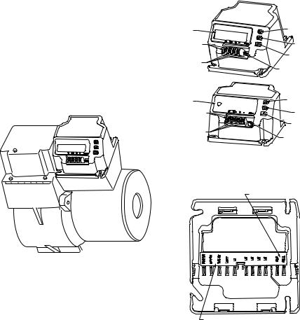
Fig. 2. R7284 terminals, connectors, LED, reset button and DIP switch locations.
CAD CELL CONNECTION
BURNER
M32085
Fig. 1. Mounting R7284 on junction box.
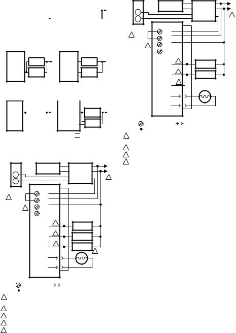
LINE VOLTAGE CONNECTIONS
M32178
Fig. 3. R7284 wiring connections.
3 |
69-2467EFS—05 |
R7284B,P,U,G ELECTRONIC OIL PRIMARY, ENVIRACOM™ ENABLED
R7284B, G |
|
|
|
|
R7284P, U |
|
|
|
|
|
… |
|
|
|
|
… |
|
|
|
|
|
|
|
|
|
LIMIT |
|
AQUASTAT |
|
|
L1 |
|
|
|
|
|
|
|
OR OTHER |
|
|
||
|
|
|
|
|
|
|
|
|||
L1 |
|
AQUASTAT |
|
|
L1 |
|
LIMIT |
|
|
|
|
OR OTHER |
|
L1 |
|
|
|
|
|
||
… |
|
LIMIT |
|
|
… |
|
|
|
|
|
|
|
|
|
|
|
|
|
M32179 |
||
Fig. 4. R7284 Limit wiring for line voltage thermostat, Aquastat, or other Limit.
R7284A, G |
|
|
R7284B, P, U |
|
|
|
… |
VALVE |
L2 |
… |
VALVE |
L2 |
|
VALVE |
||||||
|
BURNER |
BURNER |
BURNER |
BURNER |
MOTOR |
MOTOR |
MOTOR |
MOTOR |
|
… |
… |
|
M32180
Fig. 5. R7284 wiring for optional oil valve.
R7284G
…
BURNER MOTOR
…
|
|
|
|
|
|
R7284B, P, U |
|
|
|
|
|
|
… |
|
|
BURNER |
|
|
L2 |
BURNER |
|
|
MOTOR |
|
|
|
MOTOR |
|
|
|
|
|
|
IGNITER |
|
|
IGNITER |
|
|
|
|
|
|
|
|
|
||
|
|
|
|
|
|
… |
|
|
|
|
|
|
INTERMITTENT
IGNITION
BURNER |
L2 |
|
MOTOR |
||
|
IGNITER
INTERRUPTED IGNITION INTERMITTENT IGNITION
M32181
|
Fig. 6. R7284 igniter wiring. |
|
|||
|
CIRCULATION |
C1 |
AQUASTAT® |
L1 |
|
|
PUMP |
|
C2 |
CONTROLLER |
L2 |
R |
|
|
B2 |
||
|
|
|
1 |
||
|
|
|
|
T |
|
W |
|
|
|
B1 |
|
|
|
|
T |
|
|
THERMOSTAT |
R7284 |
|
L8148A,C |
|
|
|
|
|
|||
T |
LIMIT |
|
|
|
|
|
|
|
|
||
5 JUMPER |
T |
L1 |
|
|
|
|
|
|
|
||
|
3 |
L2 |
|
|
|
|
|
|
|
|
|
4 |
2 |
|
|
|
|
ENVIRACOM™ |
1 |
|
|
|
|
TERMINAL |
|
|
|
|
|
|
BURNER |
2 |
|
BURNER |
|
|
MOTOR |
|
|
MOTOR |
|
|
IGNITER |
2 |
|
IGNITER |
|
|
|
|
|
||
|
VALVE |
2 |
|
VALVE |
|
|
|
|
|
||
|
|
|
|
|
3 |
|
CAD |
|
CAD |
|
|
|
CELL |
|
CELL |
|
|
|
|
|
JUNCTION |
|
|
|
|
|
BOX |
|
|
LEGEND: |
SCREW TERMINAL |
1/4 IN. QUICK CONNECT TERMINAL |
|
SOLDERLESS WIRE CONNECTOR |
|
1POWER SUPPLY. PROVIDE DISCONNECT MEANS AND OVERLOAD PROTECTION AS REQUIRED.
2REFER TO DEVICE LABEL FOR WIRE COLOR CODE.
3VALVE IS OPTIONAL ON SPECIFIC MODELS.
4ENVIRACOM™ TERMINAL 3 IS ALSO THE FIRST THERMOSTAT TERMINAL.
5THE JUMPER MAY BE OMITTED IF THE R7284 IS CONFIGURED TO IGNORE
THE TT TERMINALS. |
M32182 |
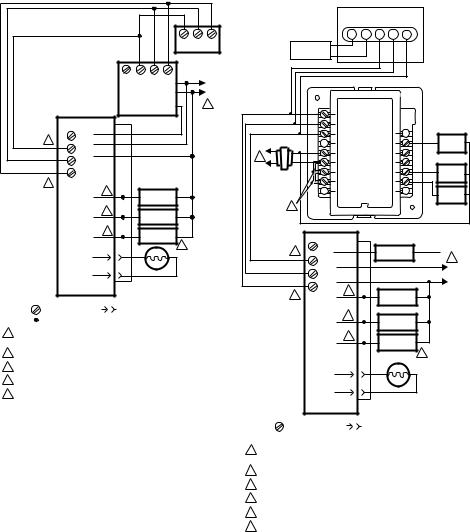
Fig. 7. Wiring R7284P,U without EnviraCOM™, for typical oil-fired boiler.
|
CIRCULATION |
C1 |
AQUASTAT® |
L1 |
|
|
PUMP |
|
C2 |
CONTROLLER |
L2 |
R |
|
|
B2 |
||
|
|
|
1 |
||
|
|
|
|
T |
|
W |
|
|
|
B1 |
|
|
|
|
T |
|
|
THERMOSTAT |
R7284 |
|
L8148A,C |
|
|
|
|
|
|||
T |
LIMIT |
|
|
|
|
|
|
|
|
||
4 JUMPER |
T |
L1 |
|
|
|
|
3 |
L2 |
|
|
|
|
|
|
|
|
|
3 |
2 |
|
|
|
|
ENVIRACOM™ |
1 |
|
|
|
|
TERMINAL |
|
|
|
|
|
|
BURNER |
2 |
|
BURNER |
|
|
MOTOR |
|
|
MOTOR |
|
|
IGNITER |
2 |
|
IGNITER |
|
|
|
|
|
||
|
VALVE |
2 |
|
|
|
|
|
|
|
|
|
|
CAD |
|
CAD |
|
|
|
CELL |
|
CELL |
|
|
|
|
|
JUNCTION |
|
|
|
|
|
BOX |
|
|
LEGEND: |
SCREW TERMINAL |
1/4 IN. QUICK CONNECT TERMINAL |
|
SOLDERLESS WIRE CONNECTOR |
|
1POWER SUPPLY. PROVIDE DISCONNECT MEANS AND OVERLOAD PROTECTION AS REQUIRED.
2REFER TO DEVICE LABEL FOR WIRE COLOR CODE.
3ENVIRACOM™ TERMINAL 3 IS ALSO THE FIRST THERMOSTAT TERMINAL.
4THE JUMPER MAY BE OMITTED IF THE R7284 IS CONFIGURED TO IGNORE
THE TT TERMINALS. |
M32191 |
Fig. 8. Wiring R7284U without EnviraCOM™, for typical oil-fired boiler.
69-2467EFS—05 |
4 |
R7284B,P,U,G ELECTRONIC OIL PRIMARY, ENVIRACOM™ ENABLED
|
|
|
|
|
3 |
2 |
1 |
|
|
T |
T/3 |
2 |
1 |
TH9421C |
|
|
|
|
|
|
|
VisionPRO IAQ |
|
|
|
|
AQUASTAT® |
|
L1 |
||
|
|
|
CONTROLLER |
|
L2 |
||
|
|
|
|
|
B2 |
|
|
|
|
|
|
|
B1 |
|
1 |
|
R7284 |
L7224/48 |
|
|
|
||
|
|
|
|
|
|
||
|
T |
LIMIT |
|
|
|
|
|
5 |
T |
L1 |
|
|
|
|
|
|
3 |
L2 |
|
|
|
|
|
|
|
|
|
|
|
|
|
|
2 |
|
|
|
|
|
|
|
1 |
|
|
|
|
|
|
4 |
|
|
|
|
|
|
|
ENVIRACOM™ |
BURNER |
2 |
|
BURNER |
|
|
|
TERMINAL |
MOTOR |
|
|
MOTOR |
|
|
|
|
IGNITOR |
2 |
|
IGNITOR |
|
|
|
|
|
|
|
|
|||
|
VALVE |
2 |
|
VALVE |
|
|
|
|
|
|
|
|
|||
|
|
|
|
|
3 |
|
|
|
CAD |
CAD |
|
|
|
||
|
CELL |
|
|
|
|||
|
CELL |
|
|
|
|||
|
|
|
|
|
|
||
|
|
JUNCTION |
|
|
|
||
|
|
BOX |
|
|
|
|
|
LEGEND: |
SCREW TERMINAL |
1/4 IN. QUICK CONNECT TERMINAL |
|
SOLDERLESS WIRE CONNECTOR |
|
1POWER SUPPLY. PROVIDE DISCONNECT MEANS AND OVERLOAD PROTECTION AS REQUIRED.
2REFER TO DEVICE LABEL FOR WIRE COLOR CODE.
3VALVE IS OPTIONAL ON SPECIFIC MODELS.
4ENVIRACOM™ TERMINAL 3 IS ALSO THE FIRST THERMOSTAT TERMINAL.
5DO NOT CONNECT THE JUMPER ACROSS THE TT TERMINALS OR CONFIGURE THE INTERNAL TT SETTING TO "YES" WHEN THE OIL PRIMARY AND AQUASTAT ARE CONNECTED VIA THE ENVIRACOM BUS.
M32183A
Fig. 9. Wiring R7284P,U with EnviraCOM™ connections, for typical oil-fired boiler.
|
T8635L |
|
|
|
|
|
C7089B |
|
|
|
|
|
|
OUTDOOR |
|
|
|
|
|
|
TEMPERATURE |
OT |
OT |
1 |
2 |
3 |
|
SENSOR |
||||||
|
|
|
|
|
|
W8635A |
|
|
|
|
|
1 |
|
|
|
|
2 |
|
|
|
|
3 |
|
|
L2 |
|
|
G |
FAN |
|
|
|
RELAY |
|
|
|
C |
W1 |
|
1 |
|
|
||
|
R |
W2 |
|
|
|
|
|
||
L1 |
|
RH |
Y1 |
COOL 1 |
(HOT) |
|
RC |
Y2 |
RELAY |
SYSTEM |
|
|
||
|
|
|
COOL 2 |
|
TRANSFORMER |
|
|
|
|
|
|
|
RELAY |
|
|
|
|
|
|
4 |
|
|
|
|
|
R7284 |
|
|
|
|
T |
LIMIT |
|
|
6 |
|
LIMIT |
|
|
T |
|
1 |
||
|
|
|
||
|
3 |
L1 |
|
|
|
|
L1 |
||
|
|
|
|
|
|
2 |
L2 |
|
HOT |
|
|
L2 |
||
|
|
|
||
|
1 |
|
|
|
|
2 |
BURNER |
|
|
5 |
BURNER |
|
||
|
|
|||
ENVIRACOM™ |
MOTOR |
|
MOTOR |
|
|
|
|
|
|
TERMINAL |
|
2 |
|
|
|
IGNITOR |
IGNITOR |
|
|
|
|
|
||
|
VALVE |
2 |
VALVE |
|
|
|
|
||
|
|
|
|
3 |
|
|
CAD |
CAD |
|
|
|
CELL |
CELL |
|
|
|
|
JUNCTION |
|
|
|
|
BOX |
|
LEGEND: |
SCREW TERMINAL |
1/4 IN. QUICK CONNECT TERMINAL |
 SOLDERLESS WIRE CONNECTOR
1POWER SUPPLY. PROVIDE DISCONNECT MEANS AND OVERLOAD PROTECTION AS REQUIRED.
IMPORTANT
When the R7284 Oil Primary is communicating to the L7224/L7248 Aquastat via the EnviraCOM bus, do not jumper the TT terminals or configure the internal TT setting to "YES". Improper burner operation will result.
2REFER TO DEVICE LABEL FOR WIRE COLOR CODE.
3VALVE IS OPTIONAL ON SPECIFIC MODELS.
4FACTORY INSTALLER JUMPERS.
5ENVIRACOM™ TERMINAL 3 IS ALSO THE FIRST THERMOSTAT TERMINAL.
6DO NOT CONNECT THE JUMPER ACROSS THE TT TERMINALS OR CONFIGURE THE INTERNAL TT SETTING TO "YES" WHEN THE OIL PRIMARY AND AQUASTAT ARE CONNECTED VIA THE ENVIRACOM BUS.
M32184B
Fig. 10. Typical wiring diagram for EnviraCOM™ enabled thermostat and R7284P,U for an oil-fired forced-air system.
IMPORTANT
System as shown in Fig. 10 is phase/polarity sensitive. Make sure all input power is in the same phase.
5 |
69-2467EFS—05 |
R7284B,P,U,G ELECTRONIC OIL PRIMARY, ENVIRACOM™ ENABLED
ADVANCED USER INTERFACE
|
|
|
UP/DOWN |
|
|
ERROR HISTORY |
|
i |
|
i |
|
|
UP/DOWN |
|
|
|
|
i |
|
i |
|
i |
|
(NO SELECTED) |
|
||
|
|
HOME SCREEN |
i |
|
|
|
|
i |
|
HOLD ALL |
|
|
3 BUTTONS |
|
|
(YES SELECTED) |
|
|
i |
CAD CELL HISTORY |
|
|
(EXIT SELECTED) |
|
|
|
|
i |
i |
i |
i |
IGNITION TIME |
|
(CONT. SELECTED) |
|
|
|
|
|
HISTORY |
|
INSTALLER SETUP |
|
i |
|
SCREENS |
|
|
|
|
|
CYCLE COUNTS |
|
i |
|
|
|
M32103A |
|
|
|
|
|
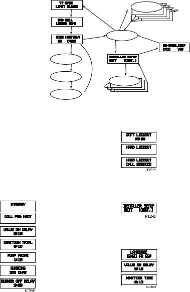
Fig. 11. User interface overview.
Home Screens
Pressing the “i” button longer than 2 seconds in states other than Standby Interrupts control operation.
Once the held key is released the count down begins.
•Holding all 3 buttons longer than 2 seconds in any state goes to Installer Setup (ISU).
•Pressing “i” in any state enters the Diagnostic screen (if diagnostics are enabled).
•Pressing up or down in any screen enters Error History (if diagnostics are enabled).
Below is a typical progression of screens through a normal cycle.
Pressing up or down during the
Ignition Trial enters pump prime.
Each press of the up button adds a minute, each press of the down button subtracts a minute from the pump prime time.
If at any point there is an event generating a lockout, one of the following screens will be displayed.
Control is in Soft Lockout. Control will recover when error clears or after specified time.
Control is in Hard Lockout. Hold “i” for at least 2 seconds to reset.
Hold the “i” button longer than 10 seconds to return to Standby.
Installer Setup
Installer setup is entered by pushing all three buttons simultaneously for 2 seconds.
If QUIT is selected, an “i” button press displays the Re-baseline option.
If CONT is selected, an “i” button press goes to “Installer Setup”.
NOTE:Not all parameters are adjustable in all models. Parameters not available for adjustment will display “Locked” when an attempt is made to modify them.
Select between English, French, or Spanish by using the up or down buttons and the “i” button to select
Adjustment of the Valve On Delay in five second increments.
Ignition (lockout) Time adjustment.
NOTE: The Ignition Time is only available for adjustment during the first 100 cycles of operation. After 100 cycles the Ignition Time is locked in and can no longer be adjusted.
69-2467EFS—05 |
6 |

R7284B,P,U,G ELECTRONIC OIL PRIMARY, ENVIRACOM™ ENABLED
Adjustment of the Burner Off Delay.
Configuration of the TT terminals vs. an “internal jumper.” Configure the TT setting to "NO" when connecting the oil primary to the L7224/L7248 Aquastat® via the EnviraCOM bus terminals 1, 2, 3.
Controls sparking during On Delay period.
Controls sparking during Run mode (Interrupted vs. Intermittent ignition).
Number of resets allowed before Restricted Lockout
Appliance configuration (boiler, furnace, water heater) for EnviraCOM™.
Enable advanced diagnostics mode and error history.
Exit installer setup
If “QUIT” is selected, the user is prompted with a screen asking if it is desired to re-baseline the control.
Baselining the control is intended as a means to save performance data at the time when the control is operating optimally. The baseline values are a “trend” of the first 500 cycles following an installation or a command to “re-baseline” and is provided as a method to compare present burner performance to that when the burner was initially installed or serviced. Using the baseline data, it is possible to monitor the burner system for degradation and allow a service person to address any issues before they result in a no-heat situation. After performing the service it may be desired to reset the baseline through the installer setup menu.
NOTE: Re-baselining will establish new baseline values for CAD cell and Ignition Time going forward. It will also reset the “Cycles Since Baseline”, “Lockouts Since Baseline”, and “Recycles Since Baseline” counters back to zero.
Displays the status of the TT and Limit inputs. Note that “TT Remote” means EnviraCOM™ is commanding the R7284 to behave opposite the status of the TT terminals.
Press “i” to go to the next screen
Current value of the CAD cell. Press “i” to go to the next screen
If NO is selected, “i” returns to the home screen
If YES is selected, “i” continues through diagnostic screens.
The history screens can provide useful information about the controls past performance, including its recent history such as cycle trends (using the baseline function) and total cycles since installation.
View History
From the Diagnostic screen scroll to the View History screen and select YES. Scroll through the performance data by using the up or down buttons.
The CAD Cell screen automatically scrolls 4 screens.
Average CAD cell value during last cycle
CAD cell trend over the last 10 cycles.
CAD cell trend over the first 500 cycles
Pressing “i” during any of the CAD cell screens moves to the Ignition Time screens below.
The Ignition Time screen automatically scrolls through 4 screens.
Last Ignition Time.
Ignition Time trend over the last 10 cycles. Ignition
Time trend over the first 500 cycles.
Pressing “i” during any of the ignition time screens moves to the Cycle Count screen below.
Total burner cycles.
Burner cycles since last service (baseline reset).
Flame losses since last service (baseline reset).
Ignition failures since last service (baseline reset).
The next press goes back to the View History screen where the user can exit to the home screen or loop back through the performance history again.
Error History Screens
For all Error History screens, pressing “i” returns to the Normal Screen.
From the home screen, press the up button to display most recent error.
Press the up button again to proceed to the next most recent error or the down button to return to the previous error screen.
These three screens transition every 3 sec.
If no more errors are logged, the display shows “Error History End.”
7 |
69-2467EFS—05 |
R7284B,P,U,G ELECTRONIC OIL PRIMARY, ENVIRACOM™ ENABLED
BASIC USER INTERFACE
The basic user interface consists of 3 buttons and an LED. Simple diagnostic information can be obtained through the interaction of the buttons and LED.
R7284 Status (Basic Interface)
|
Table 2. LED Codes. |
|
|
Description |
LED Code |
Standby |
Pulse (1/4 sec. ON, 4 sec OFF) |
|
|
Call for Heat |
Heartbeat (1/2 sec bright, 1/2 sec dim) |
|
|
Flame proven |
On solid |
|
|
Recycle |
2 second ON, 2 second OFF flashing |
|
|
Lockout |
1/2 second on, 1/2 second OFF flashing |
|
|
Interrupt |
OFF |
|
|
“i” button |
Flame Strength Indication |
|
|
Up button |
Most recent error |
|
|
Down button |
Next most recent error |
|
|
Table 4. Error Codes.
|
Number of 1/4 sec |
Error Codes |
flashes |
Flame out of sequence |
3 |
|
|
Low Voltage / EnviraCOM™ error |
4 |
|
|
Internal Error |
5 |
|
|
TROUBLESHOOTING AND MAINTENANCE
IMPORTANT
Due to the potential hazard of line voltage, only a trained, experienced service technician should preform the troubleshooting procedures.
This control contains no field-serviceable parts. Do not attempt to take it apart. Replace entire control if operation is not as described.
To completely troubleshoot an oil burner installation, check the burner and oil primary control for proper operation and condition.
R7284 Flame Strength (Basic Interface)
During normal operation and when the R7284 is in the Running state, the LED will show CAD cell resistance. See Table 3.
Table 3. Flame Strength Indication.
Flame Strength Indication Number of 1/2 sec flashes |
|
Cad Cell less than 400Ω |
1 |
400Ω < Cad Cell < 800Ω |
2 |
800Ω < Cad Cell < 1600Ω |
3 |
1600Ω < Cad Cell < 6100Ω |
4 |
Cad Cell > 6100Ω |
None |
Error History (Basic Interface)
The last two errors are available for display on the LED:
•Pressing the up arrow button displays the most recent error.
•Pressing the down arrow button displays the next most recent error.
Once the up or down arrow is pushed, the LED will display the most recent or next most recent alarm by blinking the error code. See Table 4.
R7284 Error Codes
(Basic Interface)
Table 4. Error Codes.
|
Number of 1/4 sec |
Error Codes |
flashes |
No ignition / Late ignition |
1 |
|
|
Max flame losses / Cad Cell high |
2 |
while running |
|
Cad Cell Resistance Check
For proper operation, it is important that the cad cell resistance is below 1600 ohms. On the basic model with LED interface, during a normal call for heat, once the control has entered the Run mode, press and release the “i” button.
On the advanced model with display, follow the screen diagnostic procedure to read the cad cell resistance.
Preliminary Steps
1.Check wiring connections and power supply.
2.Make sure power is on to controls.
3.Make sure limit control is closed.
4.Check contacts between igniter and the electrodes.
5.Check the oil pump pressure.
6.Check the piping to the oil tank.
7.Check the oil nozzle, oil supply and oil filter.
Check Oil Primary Control
If the trouble is not in the burner or ignition hardware, check the oil primary control by using the following equipment:
1.Screwdriver.
2.Voltmeter (0 to 150 Vac range).
3.Insulated jumper wire with both ends stripped.
 WARNING
Electrical Shock Hazard.
Can cause severe injury, death or property damage.
Troubleshoot with the system powered. Be careful to observe all precautions to prevent electrical shock or equipment damage.
69-2467EFS—05 |
8 |
|
|
|
R7284B,P,U,G ELECTRONIC OIL PRIMARY, ENVIRACOM™ ENABLED |
|
|
|
Table 5. R7284 Operation. |
|
|
|
|
External Action |
|
|
R7284 Action |
Power applied to control. |
Internal safety check conducted. If no light or flame is detected and all internal |
||
|
conditions are correct, control enters Standby Mode. |
||
Thermostat or Aquastat® Control |
1. Safety Period (5 seconds) internal and external check for flame or light. If |
||
calls for heat. |
|
flame or light is detected, control remains in the Standby Mode. |
|
|
2. |
When flame or light is not present: |
|
|
|
a. |
R7284G will apply power to the burner motor and igniter. |
|
|
b. |
R7284B,P,U (if valve-on delay is enabled) will apply power to the burner |
|
|
|
motor and igniter, (if configured) enter/complete valve-on delay period |
|
|
|
and then apply power to the valve. |
|
3. |
Control enters Trial for Ignition period. |
|
|
|
a. |
Monitors burner for flame. |
|
|
b. |
When flame is not detected: |
|
|
|
(1) Enters lockout mode (after lockout time of 15, 30, or 45 seconds). |
|
|
|
(2) Shuts off valve, igniter and burner motor. |
|
|
|
(3) Display models: display Lockout mode. LED models: flash LED 1/2 |
|
|
|
sec ON, 1/2 sec OFF. |
|
|
|
(4) Depress “i” button for 2 seconds to return to power-up sequence. |
|
|
c. |
When flame is detected, Carry-Over period begins: |
|
4. |
Control enters Ignition Carry-Over period (continues to spark for 10 seconds |
|
|
|
in interrupted mode). |
|
|
|
a. |
Display models: display “Flame Proven.” LED models: turns on LED |
|
|
b. |
If flame is lost and lockout time has not expired, R7284 returns to Trial for |
|
|
|
Ignition period. |
|
|
c. |
If flame is lost and lockout time has expired, R7284 enters Recycle Mode. |
|
5. |
Carry-Over time expires; igniter turns off if interrupted ignition. |
|
|
6. |
Enters Run Mode: |
|
|
|
a. |
Flame is monitored until call for heat ends or flame is lost. If flame is lost: |
|
|
|
(1) Control enters Recycle Mode. |
|
|
|
(2) Recycle time starts (60 seconds). |
|
|
|
(3) Burner and valve are turned off. |
|
|
|
(4) Display models: display “Recycle.” LED models: flash LED 2 sec ON, |
|
|
|
2 sec OFF. |
|
|
|
(5) Returns to Idle Mode at end of Recycle Mode. |
Call for heat is satisfied. |
1. R7284B,G,P,U (if burner motor-off delay is disabled): |
||
|
|
a. |
Burner motor and optionally oil valve and igniter shut off. |
|
|
b. |
Display models: display “Standby” |
|
|
|
LED models: LED turns OFF |
|
|
c. |
Indicator light turns off. |
|
2. R7284P,U (if burner motor-off delay is enabled): |
||
|
|
a. |
Oil valve shuts off. |
|
|
b. |
Burner motor runs for selected burner motor-off delay time. |
|
|
c. |
Burner motor turns off. |
|
|
d. |
Device returns to Idle Mode. |
Reset control three times without |
1. |
R7284 enters Restricted Mode. |
|
completing a call for heat |
2. |
Indicator light flashes and 1/2 second on, 1/2 second off. |
|
(number of resets is adjustable in |
3. Display models: display “Hard Lockout Call Service” |
||
some controls) |
|
LED models: flash LED 1/2 second ON, 1/2 second OFF |
|
|
4. Reset device by pressing and holding reset button for a minimum of 10 |
||
|
|
seconds. |
|
9 |
69-2467EFS—05 |
R7284B,P,U,G ELECTRONIC OIL PRIMARY, ENVIRACOM™ ENABLED
Table 6. Troubleshooting Information.
Condition: Burner does not start with a call for heat |
|
||
Procedure |
Control Status |
Corrective Action |
|
Review error history if |
-- |
|
Refer to Error Codes table of this section |
control in lockout |
|
|
|
Check that limit switches |
Display models: display shows |
Replace limit switch or clean contacts. |
|
are closed |
status of limit switch. |
|
|
Check TT status |
Display models: display shows |
• Most hydronic systems require TT to be jumpered. |
|
|
status of TT. |
|
Display models can be configured to behave as |
|
|
|
though the TT terminals are jumpered. LED models |
|
|
|
require a jumper be added. |
|
|
|
• Warm air systems will short TT terminals during a call |
|
|
|
for heat. Check that TT is really shorted during the |
|
|
|
call for heat. |
Check for line voltage |
-- |
|
Check breaker and investigate appliance wiring |
power at R7284 |
|
|
|
Check status of cad cell |
Display models: display shows |
• Replace cad cell |
|
|
cad cell resistance. |
• If operation does not resume, remove leadwires from |
|
|
LED models: LED is on if cad |
R7284. |
|
|
cell is too low to start. |
• If operation does not resume, replace control. |
|
Condition: Burner does not stop when call for heat ends |
|
||
Procedure |
Control Status |
Corrective Action |
|
Check TT status |
Display models: display shows |
• Check if a TT jumper is installed. When the R7284 |
|
|
status of TT. |
|
and L7224/L7248 electronic Aquastat are connected |
|
|
|
via the EnviraCOM bus, neither a physical jumper |
|
|
|
across the TT terminals or a configured TT jumper |
|
|
|
should be present on the oil primary. |
|
|
|
• Check if the R7284 is configured to ignore the TT |
|
|
|
terminals. |
|
|
|
• Verify thermostat contacts have opened. There |
|
|
|
should be 24VAC across TT terminals when there is |
|
|
|
not call for heat. |
Check limit status |
Display models: display shows |
Measure voltage on Limit terminal. There should be no |
|
|
status of limit. |
|
voltage between Limit and Neutral when the contacts are |
|
|
|
open. Replace limit switch if necessary. |
Check if other EnviraCOM |
Display models: display shows |
Unplug all EnviraCOM devices from R7284. It should |
|
devices are commanding |
"TT Remote" if an EnviraCOM |
turn off within 5 minutes. |
|
the R7284 to run |
device is commanding it to run. |
|
|
|
Table 7. Display Alarm Information. |
||
|
|
|
|
|
EnviraCOM™ |
|
|
Display Alarm |
Alarm |
|
|
Number |
|
Corrective Action |
|
No Ignition |
10 |
• The burner was not lit and spark was not detected. Check the |
|
Check Igniter |
|
electrodes, spring contacts (or high voltage wires), and ignition |
|
|
|
transformer for proper operation. |
|
|
|
• If spark ignition is functioning acceptably, proceed to “No Ignition” |
|
|
|
corrective action. |
|
No Ignition |
5 |
• The cad cell detected some amount of light during the ignition trial, but |
|
Check Cad Cell |
|
not enough to enter run mode. Check the cad cell positioning and clean |
|
|
|
the eye. |
|
|
|
• Set the display to show the cad cell resistance. |
|
|
|
• Shield the cad cell from light. |
|
|
|
• If the display shows is less than 20,000 ohms, unplug the cad cell. |
|
|
|
— If the display does not read 999999 ohms, replace control |
|
|
|
— If it does read 999999 ohms, replace cad cell. |
|
|
|
• Expose the cad cell to ambient light (generally enough light to read by |
|
|
|
is adequate) |
|
|
|
• If the display shows more than 2000 ohms, short the cad cell terminals. |
|
|
|
— If the display shows more than 5 ohms, replace control |
|
|
|
— If less than 5 ohms, replace cad cell. |
|
|
|
• If the burner still does not light, proceed to “No Ignition” corrective |
|
|
|
action. |
|
69-2467EFS—05 |
10 |
|
|
|
R7284B,P,U,G ELECTRONIC OIL PRIMARY, ENVIRACOM™ ENABLED |
|
|
Table 7. Display Alarm Information. |
|
|
|
|
|
No Ignition |
20 |
|
• Check that the manual shut off valve is open. |
|
|
|
• Check that the burner motor is spinning and the pump is generating |
|
|
|
adequate pressure. |
|
|
|
• Check the condition of the nozzle and replace if necessary. |
|
|
|
• If a valve is present, check for proper operation. |
|
|
|
• Check burner adjustments (refer to burner manufacturers instructions) |
Low Voltage |
59 |
|
• Supply voltage is low to the control. |
XX% low |
|
|
• Measure the voltage across screw terminals “2” and “3” |
|
|
|
— If it's greater than 22VAC and the error does not clear, replace |
|
|
|
control. |
|
|
|
— If it's less than 22VAC, review appliance wiring. |
Internal Error |
18, 58 |
|
• An error has been detected inside the control. Replace control if the |
|
|
|
error persists. |
Flame Proven |
34 |
|
• The cad cell is permanently in a low resistance state. It should typically |
Out of Sequence |
|
|
read much higher than 20,000 ohms when no flame is present. |
|
|
|
• Set the display to display cad cell resistance. |
|
|
|
• Shield the cad cell from light. |
|
|
|
• If the display shows less than 20,000 ohms, unplug the cad cell, |
|
|
|
— If display does not read 999999 ohms, replace control. |
|
|
|
— If it does read 999999 ohms, replace cad cell. |
|
|
|
|
Flame Proven |
23 |
|
• Flame was proven during the valve on delay period. Check the oil valve |
During On Delay |
|
|
for proper operation. |
|
|
|
• If the system does not have an oil valve, set the valve on delay to 0. |
Flame Proven |
24 |
|
• Flame remained lit during the burner off delay. Check the oil valve for |
During Off Delay |
|
|
proper operation. |
|
|
|
• If the system does not have an oil valve, set the burner off delay to 0. |
Exceeded Max Recycles |
22 |
|
• Flame was lost more than the allowed number of times. The burner |
|
|
|
lights, but does not remain lit. |
|
|
|
• Check that the fuel tank is not empty. |
|
|
|
• Check the fuel supply lines (and filter) for obstructions or air |
|
|
|
— Use the pump priming feature to purge the system of airCheck |
|
|
|
• Check that the burner motor is spinning and the pump is generating |
|
|
|
adequate pressure. |
|
|
|
• If present, check operation of the oil valve. |
|
|
|
• If the problem persists, proceed to the “Cad Cell, High During Run” |
|
|
|
corrective action. |
EnviraCOM™ Error |
91 |
|
• Communications error has been detected. |
|
|
|
• Remove all devices from the EnviraCOM™ connections, 3-pin plug |
|
|
|
and screw terminals “1-2-3”. |
|
|
|
— If the error does not clear within one minute, measure the voltage on |
|
|
|
terminals “2” and “3”. |
|
|
|
— If the voltage across terminals “2” and “3” is between 20VAC and |
|
|
|
30VAC, replace control. |
|
|
|
— If it is outside of that range, review appliance wiring. There should |
|
|
|
be approximately 24VAC across “2” and “3”. |
Cad Cell |
4 |
|
• The cad cell resistance is higher than normal while running, the system |
High During Run |
|
|
is in need of a tune up. |
|
|
|
• Check for proper alignment of the cad cell and clean the eye if |
|
|
|
necessary. |
|
|
|
• Check if the pump is generating adequate pressure. |
|
|
|
• Check burner adjustments (refer to burner manufacturers instructions). |
|
|
|
• Check for excessive soot build up in the burner and flue. |
|
|
|
• Check for flue blockage. |
Flame Proven |
9 |
|
• The burner lit very late during the trial for ignition and is susceptible to |
Late in Trial |
|
|
not lighting. |
|
|
|
• Check cad cell for proper alignment and clean if necessary. |
|
|
|
• Check burner adjustments (refer to burner manufacturers instructions) |
|
|
|
• Check electrodes and spring contacts (if equipped) and adjust per |
|
|
|
manufacturers recommendations. |
|
|
|
• Check if the pump is generating adequate pressure. |
|
|
|
• Check the fuel supply lines and filter for obstructions. |
|
|
|
|
11 |
69-2467EFS—05 |

R7284B,P,U,G ELECTRONIC OIL PRIMARY, ENVIRACOM™ ENABLED
|
|
Table 8. LED Flash Codes. |
|
|
|
|
|
|
LED |
EnviraCOM™ |
|
Flash |
Alarm |
|
Code |
Number |
Corrective Action |
110,5,20,59,9 The burner was not lit or lit near the end of the trial time.
•Check that the manual shut off valve is open.
•Check that the burner motor is spinning and the pump is generating adequate pressure.
•Check the condition of the nozzle and replace if necessary.
•Check the fuel supply lines and filter for obstructions or air.
•Check the electrodes, spring contacts (or high voltage wires), and ignition transformer for proper operation.
•If a valve is present, check for proper operation.
•Check burner adjustments (refer to burner manufacturers instructions) and spark was not detected.
•Check the cad cell positioning and clean the eye.
•Expose the cad cell to ambient light (generally enough light to read by is adequate)
—If the LED does not turn on, short the cad cell terminals,
—If the LED does not turn on, replace the control,
—If the LED turns on, replace the cad cell.
•Shield the cad cell from light.
—If the LED does not turn off, unplug the cad cell,
—If the LED does not turn off, replace the control,
—If the LED turns off, replace the cad cell.
2 |
22,4 |
Flame was lost more than the allowed number of times. The burner lights but does not remain |
|
|
lit, or the cad cell is unusually high during a run cycle. |
|
|
• Check that the fuel tank is not empty. |
|
|
• Check the fuel supply lines (and filter) for obstructions or air |
|
|
use the pump priming feature to purge the system of air |
|
|
• Check for proper alignment of the cad cell and clean the eye if necessary. |
|
|
• Check the burner motor is spinning and the pump is generating adequate pressure. |
|
|
• If present, check operation of the oil valve. |
|
|
• Check burner adjustments (refer to burner manufacturers instructions). |
|
|
• Check for excessive soot build up in the burner and flue. |
|
|
• Check for flue blockage. |
323,24,34 Flame was detected out of sequence.
•Check the oil valve for proper operation (if equipped).
•Expose the cad cell to ambient light (generally enough light to read by is adequate)
—If the LED does not turn on, short the cad cell terminals,
—If the LED does not turn on, replace the control,
—If the LED turns on, replace the cad cell.
•Shield the cad cell from light.
—If the LED does not turn off, unplug the cad cell,
—If the LED does not turn off, replace the control,
—If the LED turns off, replace the cad cell.
4 |
59,91 |
• |
Supply voltage was low to the control or a communication error has occurred. |
|
|
• |
Remove all devices from the EnviraCOM™ connections, 3-pin plug and screw terminals |
|
|
|
“1-2-3”. |
|
|
|
— Measure the voltage across screw terminals “2” and “3” |
|
|
|
If it's between 22VAC and 30VAC and the error does not clear, replace control. |
—If it's outside that range, review appliance wiring. There should be approximately 24VAC across “2” and “3”.
5 |
18, 58 |
An error has been detected inside the control. Replace control if the error persists. |
Automation and Control Solutions |
|
|
Honeywell International Inc. |
|
|
1985 Douglas Drive North |
|
|
Golden Valley, MN 55422 |
|
|
Honeywell Limited-Honeywell Limitée |
|
|
|
|
|
35 Dynamic Drive |
® U.S. Registered Trademark |
|
Toronto, Ontario M1V 4Z9 |
|
|
© 2011 Honeywell International Inc. |
|
|
customer.honeywell.com |
69-2467EFS—05 M.S. Rev. 04-11 |
|
Printed in U.S.A. |
|

Régulateur primaire à mazout électronique R7284B,P,U,G compatible EnviraCOM™
NOTICE D'INSTALLATION
APPLICATION
Le régulateur à mazout électronique R7284B,P,U,G est un régulateur primaire à mazout à allumage intermittent et interrompu à tension secteur de sécurité pour les brûleurs résidentiels à mazout, les générateurs d'air chaud à air pulsé et les chauffe-eau. Le R7284B,P,U,G utilisé avec un détecteur de flamme à cellule de cadmium fait fonctionner un brûleur à mazout, un allumeur par étincelle et une vanne à mazout en option. Le régulateur fonctionne avec un thermostat basse tension et haute tension en option. Le régulateur primaire contrôle le mazout, détecte la flamme, contrôle l'étincelle d'allumage (allumage intermittent ou interrompu) et donne l'alerte en cas de verrouillage via le bus EnviraCOM™ et le circuit d'alarme à distance.
Les régulateurs primaires à mazout de la série R7284 peuvent être utilisés avec les systèmes à air pulsé et à eau chaude. Lorsqu'ils sont utilisés avec les systèmes à eau chaude, les régulateurs Aquastat® à commutation à tension secteur assurent normalement le démarrage et l'arrêt des séquences de combustion. Avec les systèmes à air pulsé, les thermostats basse tension mécanique et électronique contrôlent le démarrage et l'arrêt du processus de combustion.
Certains systèmes à eau chaude et à air pulsé nécessitent une temporisation de mise en marche de la vanne et une temporisation de mise à l'arrêt du moteur du brûleur. Le modèle R7284 actionne une vanne à mazout qui interrompt le débit de mazout lorsque le moteur du brûleur est en marche avant la combustion (temporisation de mise en marche de la vanne) et lorsque le moteur du brûleur est en marche après la combustion (temporisation de mise à l'arrêt du moteur du brûleur).
Les modèles R7284 sont uniquement conçus pour une utilisation sur les appareils à mazout ne nécessitant pas de prébalayage et de post-balayage en tant que fonction de sécurité telle que définie dans la norme UL296. La temporisation de mise en marche de la vanne et la temporisation de mise à l'arrêt du moteur du brûleur de ce régulateur sont uniquement destinées à aider à établir le tirage et à réduire les problèmes d'écoulement de mazout après la fermeture de la vanne.
Les modèles R7284 compatibles avec EnviraCOM™ peuvent être utilisés avec les systèmes de surveillance à distance EnviraLink® et les appareils de diagnostic de poche. Utiliser uniquement les modèles R7284P et U pour le fonctionnement en réseau avec d'autres dispositifs compatibles EnviraCOM™.
CARACTÉRISTIQUES
Interface utilisateur
Il y a deux interfaces utilisateur : l'interface de base et l'interface avancée. Les deux interfaces sont constituées de trois boutons : , et « i ».
L'interface avancée a un affichage à deux lignes utilisé pour configurer les paramètres du dispositif, récupérer les informations sur le diagnostic et afficher le statut du système.
L'interface de base a un voyant DEL unique utilisé pour afficher les codes d'erreur et le statut du système.
De manière générale, le bouton « i » permet de défiler parmi les options de l'affichage et sert de touche
« Entrée » (dans les modes de configuration).
Thermostat(s)
Les régulateurs primaires à mazout sont compatibles avec les thermostats standard et les thermostats communicants EnviraCOM™.
Remises en marche limitées
Cette fonction limite le nombre d'essais de remise en marche (pour chaque appel de chaleur) à trois essais maximum. Si la flamme est perdue trois fois et ne satisfait pas à un appel de chaleur, le R7281 se verrouille.
Cycle d'amorçage de pompe
Pour faciliter la purge d'air des conduites de mazout et des filtres, le R7284 peut être placé en mode de balayage en appuyant et en relâchant le bouton avec une flèche ascendante durant l'essai d'allumage.
PUMP PRIME (Amorçage de pompe) s'affiche sur l'interface avancée avec la durée restante de l'essai d'allumage (TFI). Le fait d'appuyer sur le bouton avec flèche ascendante ajoute une minute à la durée TFI (appuyer 10 fois pour 10 minutes max. supplémentaires). Le fait d'appuyer sur le bouton avec touche descendante enlève une minute à la durée TFI.
Il n'y a pas d'indication visuelle pour la commande d'interface de base et la minuterie de balayage est limitée à cinq minutes.
RÉGULATEUR PRIMAIRE À MAZOUT ÉLECTRONIQUE R7284B,P,U,G COMPATIBLE ENVIRACOM™
Fonction de désactivation
Le fait d'appuyer sur le bouton « i » sans relâcher permet de désactiver toutes les fonctions du régulateur jusqu'à 3 secondes suivant le relâchement du bouton.
Modes de verrouillage
Le R7284 a trois types de modes de verrouillage qui sont entrés en cas d'erreur :
•Verrouillage de premier niveau : Causé par une erreur interne provisoire telle qu'une basse tension. Le régulateur se remet en marche automatiquement une fois que l'erreur n'est plus détectée.
•Verrouillage de deuxième niveau : Causé par une panne interne du régulateur ou par une panne de système telle qu'une flamme hors séquence. Un
verrouillage de deuxième niveau entraîne l'absence de chauffage. Pour annuler un verrouillage de 2e niveau, appuyer sur le bouton « i » pendant 2 secondes.
•Verrouillage de restriction : Causé par un certain nombre de verrouillages de 2e niveau consécutifs sur le même cycle de chauffage. Pour annuler un verrouillage de restriction, appuyer sur le bouton « i » pendant 10 secondes.
Résistance de la cellule de cadmium
La résistance de la cellule de cadmium peut être vérifiée sans ohmmètre.
Interface de base :
Appuyer sur le bouton « i » et le relâcher. Les clignotements qui suivent indiquent la résistance. Voir le Tableau 3.
Interface avancée :
La résistance de la cellule de cadmium est illustrée sur l'affichage.
Temporisation d'ouverture de vanne/temporisation de mise à l'arrêt du moteur de soufflante
Certains modèles peuvent avoir des temporisations fixes ou réglables pour l'ouverture de la vanne et l'arrêt du moteur de soufflante. Les circuits de sécurité vérifient la flamme durant ces temporisations, et si une flamme est présente, causent le verrouillage du régulateur.
CARACTÉRISTIQUES
Modèles :
Le Tableau 1 indique les caractéristiques principales du R7284.
Minuterie :
Temporisation d'ouverture de vanne : 0-30 secondes Temporisation d'arrêt du brûleur : 0-8 minutes
Verrouillage : 15, 30 ou 45 secondes.
Remise en marche : 60 secondes (fixe).
Report d'allumage : 10 secondes (fixe).
REMARQUE : Certains modèles ont une temporisation d'ouverture de vanne, d'arrêt de brûleur et des minuteries de verrouillage réglables.
Caractéristiques électriques :
Entrées :
Tension : 102 à 132 V c.a., 120 V c.a. nominaux. Courant : 0,5 A plus charges du moteur du brûleur, de
la vanne et de l'allumeur. Fréquence : 60 Hz.
Sorties :
Contacts de relais :
Brûleur : 120 V c.a., 10 A à pleine charge, 60 A à rotor bloqué.
Vanne : 120 V c.a., 1A. Allumeur : 120 V c.a., 3 A.
Coupure basse tension : 80 V c.a.
Courant de thermostat disponible : 100 mA. Courant EnviraCOM™ disponible : 150 mA.
REMARQUE : Réduire l'ampérage à pleine charge du brûleur de la charge de l'allumeur. Par exemple, si l'allumeur tire 3 A (120 V c.a., 360 VA), réduire l'ampérage à pleine charge du moteur du brûleur à 7 A.
Code de couleur de fil de composant typique :
Blanc : neutre. Noir : secteur. Orange : moteur.
Bleu ou bleu rayé blanc : allumeur. Violet : vanne.
Rouge : limite.
REMARQUE : Le R7284 est fourni avec des bornes à connexion rapide de 1/4 po.
Caractéristiques environnementales :
Température de fonctionnement/d'expédition : -40 °C à +66 °C (-40 °F à +150 °F).
Le texte d'affichage peut ne pas être visible à des températures inférieures à -20 °C (-4 °F).
Humidité : 0 à 95 % d'humidité relative à 40 °C (104 °F), sans condensation.
Accessoires :
Module d'alarme W8735S3000
Homologations :
Underwriters Laboratories Inc. : Reconnu (Dossier MP268).
Underwriters Laboratories Inc. du Canada.
|
|
|
Tableau 1. Modèles R7284. |
|
|
|
|
Modèle |
Limite |
Vanne |
Remarques |
R7284B |
Non |
Oui |
Temporisation d'ouverture de vanne uniquement |
|
|
|
|
R7284G |
Non |
Non |
Pas de temporisation de marche/arrêt, allumage intermittent (allumeur à fil avec moteur) |
|
|
|
|
R7284P |
Oui |
Oui |
Temporisations de marche et arrêt |
|
|
|
|
R7284U |
Oui |
Oui |
Temporisations de marche et arrêt |
|
|
|
|
69-2467EFS—05 |
14 |
Loading...