


LXiH
Table of contents
 Loading...
I
N
LXi SERIES DISHWASHER
S
LXi SERIES DISHWASHER
T
R
U
C
T
I
O
N
S
MODELS
LXiC ML-130016
LXiH ML-130017
LXiGC ML-130018
LXiGH ML-130019
701 S. RIDGE AVENUE
TROY, OHIO 45374-0001
937 332-3000
www.hobartcorp.com
FORM 34779 Rev. B (Sept. 2005)

© HOBART CORPORATION, 2003
– 2 –

TABLE OF CONTENTS
GENERAL ............................................................................................................................................ 4
INSTALLATION ................................................................................................................................... 5
Unpacking ...................................................................................................................................... 5
Location .......................................................................................................................................... 5
Leveling........................................................................................................................................... 5
Water Requirements ...................................................................................................................... 5
Plumbing Connections ................................................................................................................... 6
Electrical Connection ..................................................................................................................... 7
Electrical Data ................................................................................................................................7
Detergent and Rinse Aid................................................................................................................ 8
Operator Programming Mode ........................................................................................................ 9
Chemical Sanitizer (LXiC and LXiGC)........................................................................................ 12
OPERATION...................................................................................................................................... 12
Before First Use ........................................................................................................................... 12
Controls ........................................................................................................................................ 12
Operating the LXi Dishwasher .................................................................................................... 13
Diagnostic Messages .................................................................................................................. 14
Wash/Rinse Cycle Times (LXi) ................................................................................................... 14
Wash/Rinse Cycle Times (LXiG) ................................................................................................ 14
Preparation ................................................................................................................................... 15
Do's and Don'ts For Your New Hobart Dishwasher .................................................................. 16
CLEANING......................................................................................................................................... 17
Priming Chemical Pumps ............................................................................................................ 18
MAINTENANCE................................................................................................................................. 19
Deliming ........................................................................................................................................19
Lubrication .................................................................................................................................... 19
TROUBLESHOOTING ...................................................................................................................... 20
– 3 –
Installation, Operation and Care of
LXi SERIES DISHWASHERS
SAVE THESE INSTRUCTIONS
GENERAL
The LXi Series dishwashers are fully automatic, front-loading dishwashing machines that are capable
of 30 racks per hour.
All LXi Series dishwashers shut down automatically 4 hours after last use to conserve energy.
All LXiH and LXiGH dishwashers include
during rinse.
Standard equipment includes two 20" x 20" racks, electronic controls, drain pump, fill hose and drain
hose.
MODEL DESCRIPTION
LXiC Fresh water rinse; low-temperature, chemical-sanitizing models for use
with 6% sodium hypochlorite solution (bleach) as the sanitizing agent.
Note: If 8.40% bleach is to be used, contact Hobart Service to change the
sanitizer pump settings. (Charges will apply)
LXiH Fresh water rinse with a built-in 70°F rise booster heater. This allows an
incoming water temperature of 110°F.
Sense-A-TempTM
to insure proper hot water temperature
– 4 –

INSTALLATION
UNPACKING
Immediately after unpacking the dishwasher, check for possible shipping damage. If this machine is
found to be damaged, save packaging material and contact the carrier within 15 days of delivery.
LOCATION
Prior to installation, verify that the electrical supply agrees with the specifications on the machine data
plate, which is located on the top of the door.
Steam generated from normal operation may escape from the door. Wood, laminates, veneers, etc. are
unsuitable materials for use in areas exposed to dishwasher steam and detergents. Stainless steel or
other moisture-resistant shields are recommended for surfaces adjacent to LXi sides and top.
LEVELING
The machine must be level to operate properly. Place the dishwasher in its operating location. Level
the machine before any connections are made. Using a carpenter's level placed diagonally on the rack
tracks, level the machine front to back and side to side by threading the adjustable feet in or out. After
leveling the machine, cover the exposed threads of the adjustable feet with black rubber tubing
supplied. (See separate instructions furnished with machine.)
WATER REQUIREMENTS
Proper water quality can improve warewashing performance by reducing spotting, lowering chemical
supply costs, enhancing effectiveness of labor and extending equipment life. Local water conditions
vary from one location to another. The recommended proper water treatment for effective and efficient
use of this equipment will also vary depending on the local water conditions. Ask your municipal water
supplier for details about local water specifics prior to installation.
Recommended water hardness is 4 - 6 grains of hardness per gallon. Chlorides must not exceed 50
parts per million. Water hardness above 6 grains per gallon should be treated by a water conditioner
(water softener or in-line treatment). Water hardness below 4 grains per gallon also requires
treatment to reduce potential corrosion. Water treatment has been shown to reduce costs associated
with machine cleaning, reduce deliming of the dishwasher, reduce detergent usage and reduce
corrosion of metallic surfaces in the booster water heater and dishwasher.
Sediment, silica, chlorides or other dissolved solids may lead to a recommendation for particulate
filtration or reverse osmosis treatment.
If an inspection of the dishwasher or booster heater reveals lime buildup after the equipment has been
in service, in-line treatment should be considered. If recommended, follow suppliers installation and
use instructions. Contact your local Hobart Service Office for specific recommendations.
Water
– 5 –

Water Supply
A water hammer arrestor (meeting ASSE-1010 Standard or equivalent) should be installed (supplied
by others) in the common water supply line at the service connection.
Water must be proper hardness. Higher hardness may cause excessive formation of lime scale.
The plumber connecting this machine is responsible for making certain that water lines are
THOROUGHLY FLUSHED OUT BEFORE connecting to the dishwasher. This "flush-out" is necessary
to remove all foreign matter, such as chips (resulting from cutting or threading of pipes) pipe joint
compound from the lines; or, if soldered fittings are used, bits of solder or cuttings from the tubing.
Debris, if not removed, may lodge in the dishwasher's plumbing components and render them
inoperative. Manual valves or solenoid valves fouled by foreign matter and any expenses resulting from
this fouling, are NOT the responsibility of the manufacturer.
Water supply requirements are as follows:
MODEL TEMPERATURE FLOWING PRESSURE
LXiC 140°F Minimum 15 to 25 psi
LXiH 110°F Minimum 15 to 25 psi
If flowing pressure exceeds 25 psi, a pressure reducing-valve (not supplied) must be installed in the
supply line.
CAUTION: The water pressure regulator must have a relief bypass. Failure to use the proper
type of pressure regulator may result in damage to the unit.
If flowing pressure is less than 15 psi, improper machine operation may result.
A manual shutoff valve (not supplied) should be installed upstream of the fill hose to accommodate
servicing the machine.
It is recommended that a line strainer (not supplied) be installed in the supply line between the manual
shutoff valve (not supplied) and the connection point on the machine. Make plumbing connections with
1
/2" minimum copper piping OD (3/4" recommended), with a 3/4" male garden hose fitting (not supplied).
See installation diagrams, pages 10-11.
NOTE: Iron in the water supply can cause staining. An iron filter is recommended for iron concentration
greater than 0.1 part per million. High chloride levels in the water supply can cause pitting. A chloride
removal system is required if levels exceed 50 parts per million.
PLUMBING CONNECTIONS
WARNING: PLUMBING CONNECTIONS MUST COMPLY WITH APPLICABLE SANITARY, SAFETY
AND PLUMBING CODES.
Drain
A drain hose,
3
/4" diameter and 6' long, is provided. This should be securely plumbed into the sink
drain. Use care not to kink hose. See installation diagrams in this manual. Drain must have a minimum
flow capacity of 4 gallons per minute.
– 6 –

ELECTRICAL CONNECTION
WARNING: ELECTRICAL AND GROUNDING CONNECTIONS MUST COMPLY WITH THE
APPLICABLE PORTIONS OF THE NATIONAL ELECTRICAL CODE AND/OR OTHER LOCAL
ELECTRICAL CODES.
WARNING: DISCONNECT THE ELECTRICAL POWER TO THE MACHINE AND FOLLOW
LOCKOUT / TAGOUT PROCEDURES.
ELECTRICAL DATA
Complied in accordance with the National Electrical Code NFPA-70, latest addition.
NOTE:For supply connections, use copper wire only rated at 90°C minimum.
ledoM esahP/ztreH/stloV
tiucriCylppuSmuminiM
yticapmArotcudnoC
evitcetorPmumixaM
yticapmAeciveD
1/06/021
CiXL
CGiXL
02021/06/042-802
*1/06/)W3(042-802/021
1/06/042/802
0505
*1/06/)W3(042-802/021
HiXL
HGiXL
3/06/042-8025353
3/06/004-0835252
3/06/0840202
HiXL1/05/042-0220505
*The (3W) systems require three power wires that include a current carrying neutral. An additional
fourth wire must be provided for machine ground.
Refer to the data plate on the door handle of the machine and the label inside the control drawer at the
power connection for proper selection.
Use stranded copper wire suitable for at least 90°C.
– 7 –
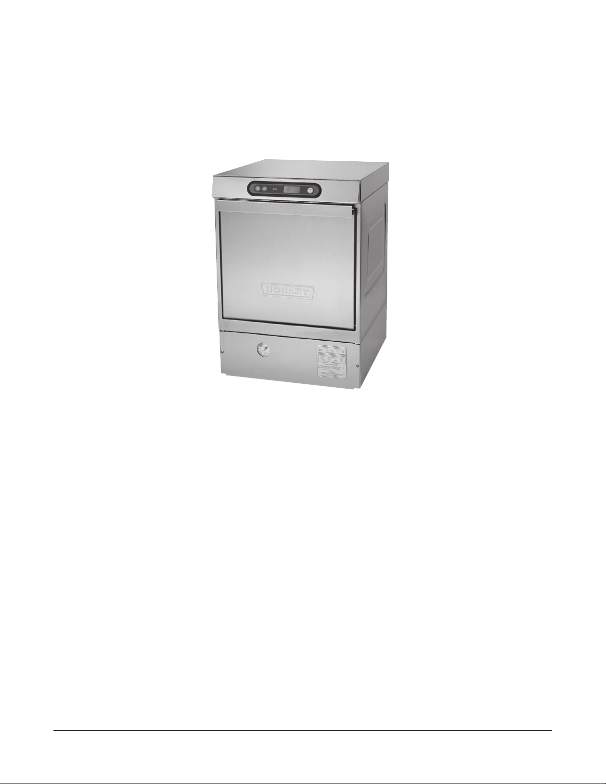
Connection Method
1. Remove the cover plate at the upper right in the back of the machine (Fig. 1). A hole for 1" trade
size conduit is supplied in the cover plate.
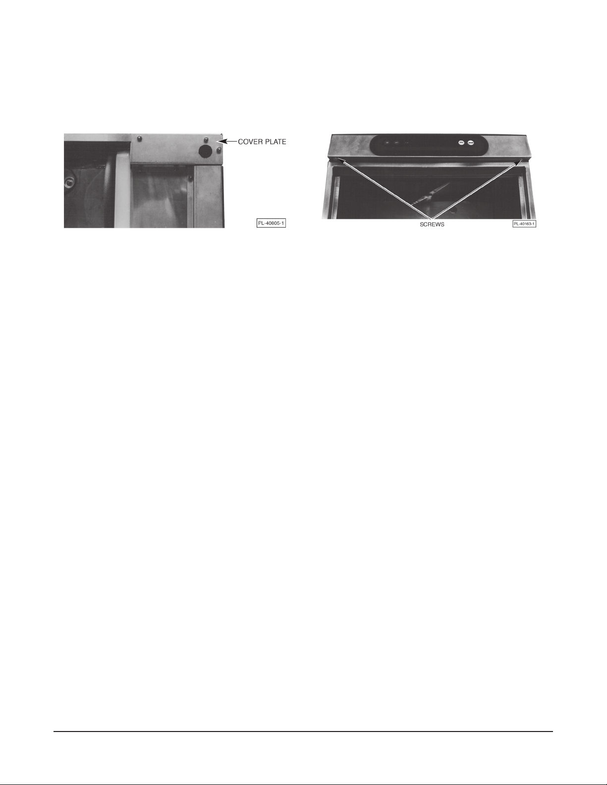
Fig. 1 Fig. 2
2. Remove the two screws (Fig. 2) securing the controls drawer and open it fully.
3. Install 1" trade conduit and fitting to the cover plate. A 90 degree fitting is recommended. Leave
at least four feet of electrical line between wall connection and cover plate connection. This
allows machine to be pulled away from the wall for cleaning.
4. Feed wires over top of tank to individual strain reliefs at rear of drawer. At least 32" and not more
than 36" of the required wire size must extend from the end of the conduit fitting.
5. Reinstall the cover plate (three screws, Fig. 1).
6. For all wires, run one wire through each individual strain relief. (Four strain reliefs are provided.)
Make electrical connections according to wiring diagram supplied with the machine and secure
wires to the machine service connection. Keep excess wire in the drawer to a minimum.
7. Tighten the set screw on the strain relief(s) until they bottom out (on the shoulder of the body).
8. Close the control drawer and replace the screws.
DETERGENT AND RINSE AID
Use only commercial-grade detergents recommended by your chemical professional. Do not use
detergents formulated for residential dishwashers.
The detergent and rinse aid pump "ON" times are factory-set. If adjustments are required, contact your
local Hobart Service Office.
Place the detergent and rinse aid containers (which are obtained from an independent supplier) in a
location where the delivery tubes will reach them.
Remove the detergent bottle cap and put the
Remove the rinse aid bottle cap and place the
red
delivery tube in the detergent container.
blue
delivery tube in the rinse aid container.
Be sure to push the delivery tube standpipes completely to the bottom of each container. Check to make
sure there are no obstructions or kinks in the delivery tubes.
– 8 –
Loading...