

HHFC SERIES
DELI DISPLAY CASES
MODEL
HHFC4 ML-114911 High Profile (573⁄8" High)
ML-114917 Low Profile (481⁄2" High)
ML-126809 Two Tier
ML-126810 Pedestal
ML-126821 Designer
HHFC4C ML-114914 Counter
HHFC5 ML-126815 High Profile (573⁄8" High)
ML-126816 Low Profile (481⁄2" High)
HHFC5C ML-126831 Counter
HHFC6 ML-114912 High Profile (573⁄8" High)
ML-114918 Low Profile (481⁄2" High)
ML-126811 Two Tier
ML-126812 Pedestal
ML-126822 Designer
HHFC6C ML-114915 Counter
HHFC8 ML-114913 High Profile (573⁄8" High)
ML-114919 Low Profile (481⁄2" High)
ML-126813 Two Tier
ML-126814 Pedestal
ML-126823 Designer
HHFC8C ML-114916 Counter
HHFC SERIES
DELI DISPLAY CASE
HIC4 ML-126817 Island Case
701 S. RIDGE AVENUE
TROY, OHIO 45374-0001
937 332-3000
www.hobartcorp.com
FORM 33798 Rev. A (Sept. 2001)
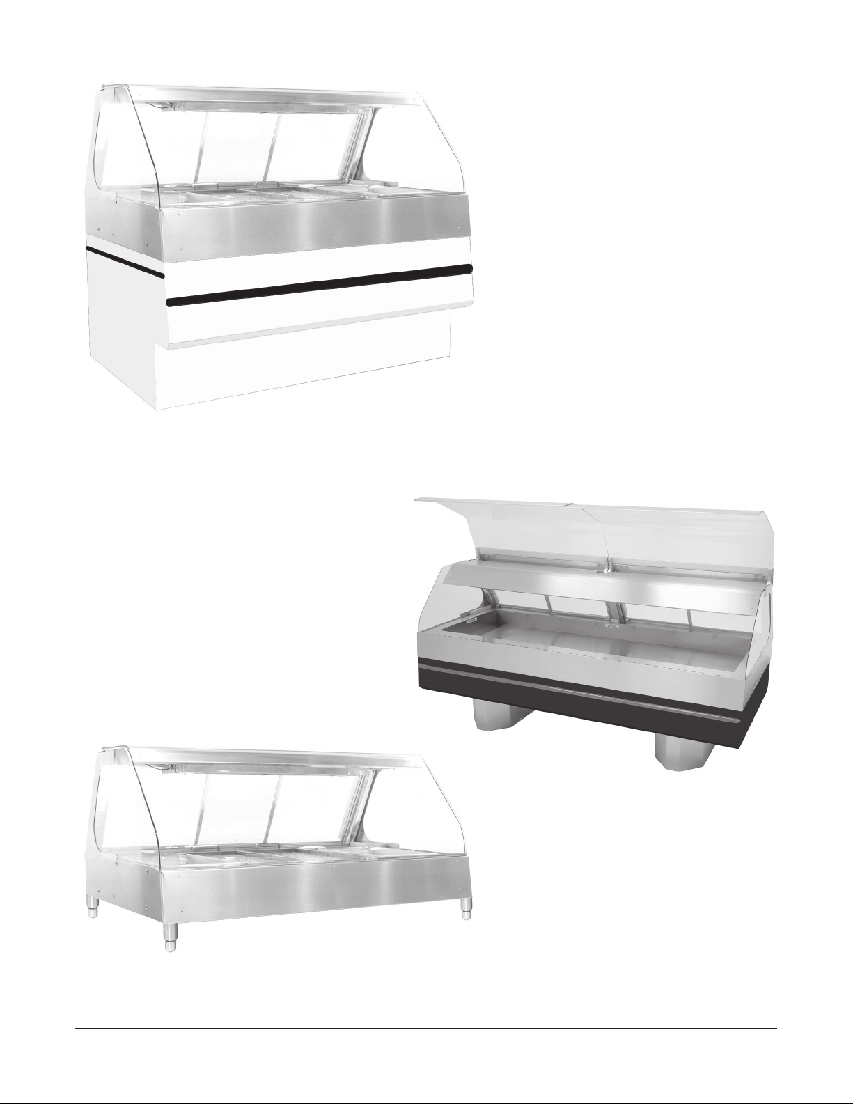
Euro Base
High or Low Profile
4, 5, 6 or 8 Foot
Full Service or Self-Service
Pedestal Base
4, 6 or 8 Foot
Full Service or Self-Service
Countertop Model
4, 5, 6 or 8 Foot
Full Service or Self-Service
© HOBART CORPORATION, 1997, 2001
– 2 –
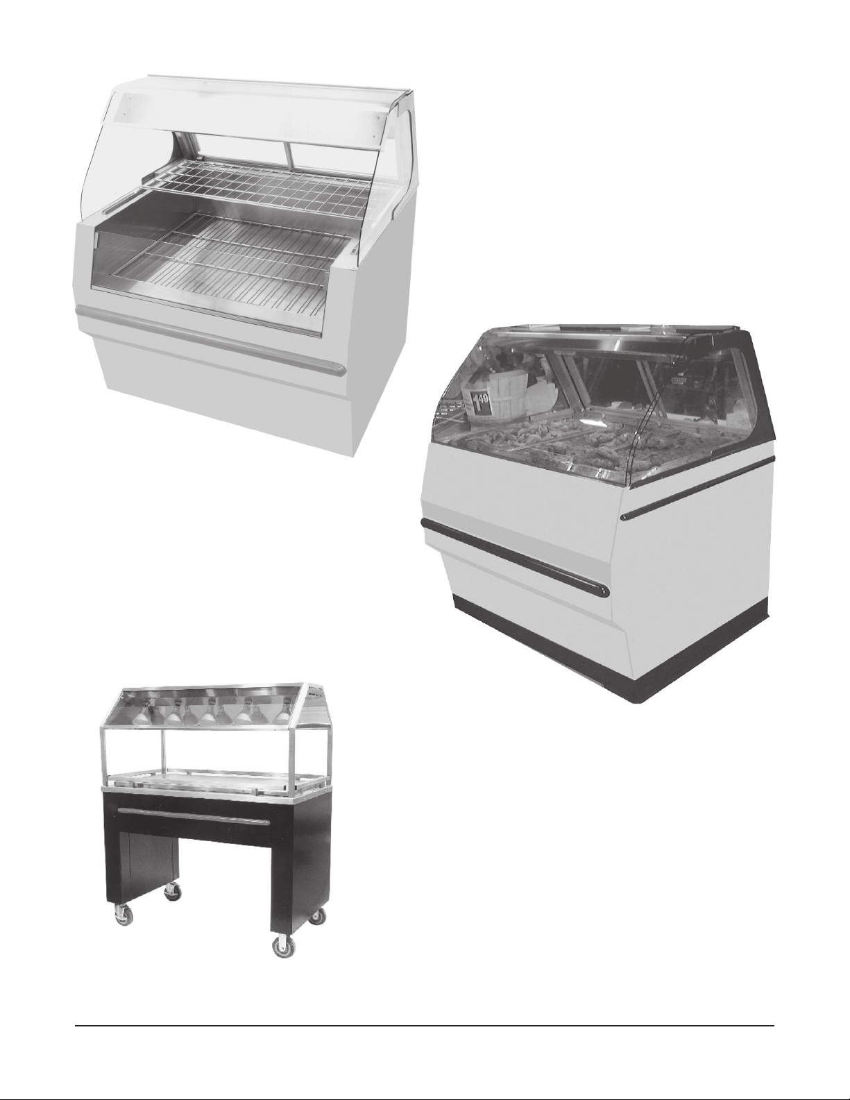
Two Tier
4, 6 or 8 Foot
Self-Service
Designer Base
4, 6 or 8 Foot
Full Service or Self-Service
Island Case
4 Foot
Self-Service
– 3 –

Installation, Operation and Care of
HHFC SERIES DELI DISPLAY CASES
SAVE THESE INSTRUCTIONS
GENERAL
The HHFC Series Deli Display Cases hold food products at regulated temperatures, maintaining both
freshness and quality. The deli cases feature uniform heating. Clear-view glass surrounds the food
holding area. Full Service units provide the customer a full view of the displayed food products. SelfService or Partial Self-Service units provide an opening to permit the customer to get-it-and-go.
Overhead radiant heater and halogen lighting is standard. Overhead radiant heat lamp bulbs are
optional.
The deli cases have an easily accessible control panel and hold a variety of pan configurations.
INSTALLATION
Prior to installation, check the electrical service to make sure that it agrees with the specifications on
the data plate located on the electrical inspection plate beside the controls.
UNPACKING
Immediately after unpacking the deli case, check for possible shipping damage. If the deli case is found
to be damaged, save the packaging material and contact the carrier within 15 days of delivery.
The deli case is shipped on a full skid and is wood crated. All deli case components, such as side glass,
divider bars and bulbs, are separately boxed and shipped in the well area of the deli case.
1. Remove the top part of the crate first.
2. Remove the side parts of the crate.
3. Remove the PVC shrink-wrap material from around the unit. Care should be taken when removing
the protective shrink-wrap material.
4. Remove the end parts of the crate.
5. The glass side panels are packed in a separate carton and must be installed. The carton containing
the glass panels is secured in the well of the deli case. Take care when opening the carton to avoid
possible damage or breakage to the glass.
6. To remove the deli case from the shipping skid:
On a Countertop Model, cut and remove the retaining bands that secure the unit to the skid.
On display cases intended to be set on the floor, remove the retaining bolts located in each corner
of the base of the deli case.
Depending on the model of the deli case, it may be necessary to remove the sandwich preparation
board first. To remove the sandwich preparation board, place the board in its down position. The
board can then be lifted in an upward direction and removed from the hinging mechanism. It is not
necessary to remove any screws or the hinging mechanism.
LOCATION
The installation location must allow adequate clearances for servicing and proper operation.
– 4 –

INSTALLATION CODES AND STANDARDS
In the United States, Hobart HHFC Series Deli Display Cases must be installed in accordance with
state and local codes and the National Electrical Code, ANSI/NFPA-70 (latest edition).
In Canada, Hobart HHFC Series Deli Display Cases must be installed in accordance with local codes
and the Canadian Electrical Code Part 1, CSA Standard C22.1 (latest edition).
ASSEMBLY
Installation of Glass Side Panels
CAUTION: Handle glass panels with care during installation to avoid breakage. The glass side
panels and front viewing glass are tempered safety glass. If the edges of the glass come in contact
with concrete, stainless steel or other hard surfaces, breakage may occur.
1. Prior to installing the side glass, it is necessary to remove the front (customer's side) stainless steel
.
front well cover (all models except Two Tier and Designer)
This is the front cover located even with
the well. To remove the front well panel, lift the front glass into the upright position. Then carefully
pull the front well panel from the case. The front well panel snaps into place. You must pull hard
to remove.
2. When installing the side glass panels, it may be necessary to lift the lighting canopy to make sure
that the side glass panel follows the track where it is intended to fit. The canopy is designed for
this in order to properly fit the glass.
3. Install one side glass panel at a time, taking care to avoid fracturing the glass. Do not slide the glass
on the stainless steel surfaces. Push the glass panels all the way back. Notice where the front glass
rests when in the down position. The front edge of the side glass panels should stop just beyond
where the front glass rests in the down position.
4. After installing the side glass panels, replace the stainless steel front well panel by snapping it in
place. Lower the front glass panel slowly so it does not hit the side glass panel edges. Once the
front glass is in the down position, move the side glass panels forward so they come as close as
possible to the front glass panel without touching it. The deli case has been specifically designed
so the side panels and front glass do not touch each other in order to avoid possible fracture.
Installation of Divider Bars
Well divider bars are supplied with each case, with the exception of Two Tier models. The long divider
bars are placed onto the divider stationary brackets located in the case well. The long divider bars run
from the front of the case (customer side) to the back of the case (operator side). The short divider bars
are placed between the long divider bars to allow the operator to use varying pan sizes in the case.
Well Divider Bars
Depending upon the model, well divider bars are provided in the quantities shown in the table.
latsedeP,oruE
rengiseDro
4CFHH:sledoM
C4CFHHro
sraBrediviDtrohS6801410
sraBrediviDgnoL23460
latsedeP,oruE
rengiseDro
5CFHH:sledoM
C5CFHHro
latsedeP,oruE
rengiseDro
6CFHH:sledoM
C6CFHHro
latsedeP,oruE
rengiseDro
8CFHH:sledoM
C8CFHHro
:sledoMreiTowT
,5CFHH,4CFHH
8CFHHro6CFHH
– 5 –

Installation of Light Bulbs or Heat Lamps
Unpack light bulb(s) or heat lamp(s) and install in socket(s). If your model has halogen light bulbs, use
a soft cloth to handle them. Human contact with halogen bulbs can reduce bulb life.
Installation of Two-Foot Self-Service Section (Optional)
The Two-Foot Self-Service Section (Fig. 1,
right side) permits previously packaged hot
foods to be displayed and allows the
customer to grab-it-and-go. The Two-Foot
Self-Service Section consists of the following
components: A fabricated stainless steel
well adapter insert, an 18 x 26" insert tray, a
raised wire grid insert for the insert tray and
a mid-divider glass panel.
The mid-divider glass panel is certified
tempered safety glass.
For those cases where the Two-Foot SelfService Section and the Two-Foot Tile Insert
option are both furnished, the following
components are used: A fabricated stainless
steel well adapter insert, an insert tile tray
and a mid-divider glass panel.
Fig. 1
1. Lift the front glass into the upright position.
2. Remove the operator side service doors.
3. Place the stainless steel well adapter insert into the deli case well on the side (left or right) that is
provided with the two-foot wide short piece of front glass.
4. Align the mid-divider glass bracket located on the stainless steel insert with the glass bracket
located under the overhead heater assembly.
5. Install the mid-divider glass taking care to avoid fracturing the glass. Do not slide the glass on the
stainless steel surfaces.
6. After installing the mid-divider glass, lower the front glass slowly and make sure it does not hit the
side edge of the mid-divider glass. Notice where the front glass rests when in the down position.
The front edge of the mid-divider glass should stop just beyond where the front glass rests in the
down position. The mid-divider glass should come as close as possible to the front glass panel
without touching it. The deli case has been specifically designed so the mid-divider glass and front
glass do not touch each other in order to avoid possible fracture.
7. Place the 18 x 26" tray insert into the Two-Foot Self-Service adapter.
8. Place the raised wire grid insert into the 18 x 26" tray insert. The raised wire grid keeps the
packaged hot food products off the surface of the insert and level with the well surface.
– 6 –

ELECTRICAL CONNECTIONS
WARNING: ELECTRICAL AND GROUNDING CONNECTIONS MUST COMPLY WITH THE
APPLICABLE PORTIONS OF THE NATIONAL ELECTRICAL CODE AND/OR OTHER LOCAL
ELECTRICAL CODES.
WARNING: DISCONNECT ELECTRICAL SUPPLY AND PLACE A TAG AT THE DISCONNECT
SWITCH TO INDICATE THAT YOU ARE WORKING ON THE CIRCUIT.
Make electrical connections per the wiring diagram shipped with the deli case. Refer to the electrical
specifications on the data plate.
OPERATION
WARNING: THE DELI CASE AND ITS PARTS ARE HOT. USE CARE WHEN OPERATING,
CLEANING OR SERVICING THE DELI CASE.
CAUTION: The deli case is designed to operate without moisture. Do not place any water in the
well of the heated deli cabinet.
Your display case is equipped with either overhead radiant heat lamp bulbs and well heating elements
(page 8) or with overhead radiant heating elements with overhead halogen lamps and well heating
elements (pages 9 – 14). The combination of overhead heat and well heat generates the required heat
for food holding requirements. Each of these components operates independent of the other. Due to
the differences in food product densities, some food products will require higher or lower heat settings
than others.
Depending on the case type, model and size, the control panel operating decal will vary. The following
summarizes the configuration of the controls.
– 7 –

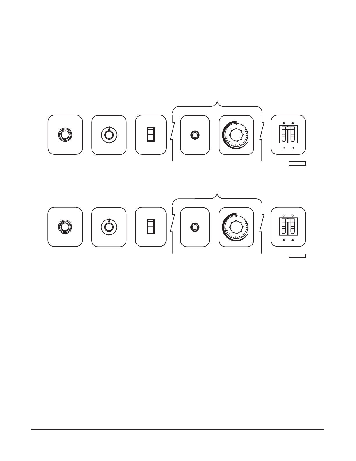
CONTROLS — All Models with Overhead Radiant Heat Lamp Bulbs, Euro, Counter, Designer,
Two Tier or Pedestal Models, Full Service or Self-Service, Model HHFC4 (Case Length: 4 Foot),
Model HHFC5 (Case Length: 5 Foot), Model HHFC6 (Case Length: 6 Foot) or Model HHFC8 (Case
Length: 8 Foot)
The size of the deli case and the model number determine the number of heating zones required to
maintain temperature in the display case. Each zone has a separate heating element and overhead
heat lamp. Each zone has its own thermostat, heating indicator light and light rheostat. Monitor case
temperatures throughout the day as required.
HEATING INDICATOR LIGHT
FUSE HOLDER
THERMOSTAT
LIGHT RHEOSTAT
Thermostat — Regulates the well heating elements to maintain the set temperature.
Settings range from 1 to 10 (Low to High).
Heating Indicator Light — When lit, the heating element is providing heat to that zone.
Light Rheostat — Adjusts the amount of overhead radiant heat from heat lamp bulbs.
Fuse Holder — Replace fuse with same size and type.
CONTROLS — Island Case, Self-Service, Model HIC4 (Case Length: 4 Foot)
One thermostat control adjusts the well heaters for the entire case. One switch controls all overhead
radiant heat lamp bulbs. Monitor case temperatures throughout the day as required.
Well Thermostat — Regulates the well heating
elements to maintain the set
temperature.
Overhead Heater Switch — Turns the overhead radiant
heat lamp bulbs On or Off.
Well Heater Switch — Turns the bottom (well) heaters
On or Off.
– 8 –

CONTROLS — Countertop, Euro Style or Pedestal, Model HHFC4 or HHFC4C (Case Length:
4 Foot), with Overhead Heater and Halogen Lighting
Each zone has its own separate heating element with thermostat control and heating indicator light.
One control adjusts the overhead heater for the entire case. One switch controls all overhead lights.
Monitor case temperatures throughout the day as required.
Full Service
HIGH
MED
LOW
OFF
OVERHEAD
HEATER
Self-Service
OFF
OVERHEAD
HEATER
ZONE CONTROL
WELL
OFF
10
9
1
THERMOSTAT
8
7
2
6
3
5
4
ZONE CONTROL
WELL
OFF
10
9
1
THERMOSTAT
8
7
2
6
3
5
4
WELL
INDICATOR
LIGHT
WELL
INDICATOR
LIGHT
OVERHEAD
LIGHTS
ON/OFF
OVERHEAD
LIGHTS
ON/OFF
FUSE HOLDER
FUSE HOLDER
MAIN (ON/OFF)
PL-53651
MAIN (ON/OFF)
PL-53656
Overhead Heater — Regulates the heating elements to Low, Medium or High settings.
Well Thermostat — Regulates the well heating elements to maintain the set temperature.
Settings range from 1 to 10 (Low to High). Zone Controls are repeated
for each zone on longer cases.
Well Indicator Light — When lit, the well heating element is providing heat to that zone.
Overhead Lights — Turns the overhead halogen lights On or Off.
Fuse Holder — Replace fuse with same size and type.
Main Circuit Breaker — Turns power to the display case On or Off.
– 9 –
CONTROLS — Countertop, Euro Style or Pedestal, Model HHFC5 or HHFC5C (Case Length:
5 Foot), Model HHFC6 or HHFC6C (Case Length: 6 Foot), with Overhead Heater and Halogen
Lighting
Each zone has its own separate heating element with thermostat control and heating indicator light.
One control adjusts the overhead heater for the entire case. One switch controls all overhead lights.
Monitor case temperatures throughout the day as required.
ZONE CONTROL
Full Service
FUSE HOLDER
Self-Service
FUSE HOLDER
OFF
HIGH
OVERHEAD
HEATER
OFF
OVERHEAD
HEATER
LOW
OVERHEAD
LIGHTS
ON/OFF
OVERHEAD
LIGHTS
ON/OFF
WELL
INDICATOR
LIGHT
ZONE CONTROL
WELL
INDICATOR
LIGHT
WELL
OFF
10
1
7
2
6
3
5
4
THERMOSTAT
WELL
OFF
10
1
7
2
6
3
5
4
THERMOSTAT
MAIN (ON/OFF)
9
8
PL-53657
MAIN (ON/OFF)
9
8
PL-53653
Fuse Holder — Replace fuse with same size and type.
Overhead Heater — Regulates the heating elements to Low, Medium or High settings.
Overhead Lights — Turns the overhead halogen lights On or Off.
Well Indicator Light — When lit, the well heating element is providing heat to that zone.
Well Thermostat — Regulates the well heating elements to maintain the set temperature.
Settings range from 1 to 10 (Low to High). Zone Controls are repeated
for each zone on longer cases.
Main Circuit Breaker — Turns power to the display case On or Off.
– 10 –

CONTROLS — Countertop, Euro Style or Pedestal, Model HHFC8 or HHFC8C (Case Length:
8 Foot), with Overhead Heater and Halogen Lighting
Each zone has its own separate heating element with thermostat control and heating indicator light.
One control adjusts the overhead heater for the entire case. One switch controls all overhead lights.
Monitor case temperatures throughout the day as required.
Full Service
ZONE CONTROL ZONE CONTROL
WELL
INDICATOR
LIGHT
WELL
OFF
1
2
6
3
5
4
THERMOSTAT
OVERHEAD
10
9
8
7
OFF
HIGH
OVERHEAD
HEATER
LOW
LIGHTS
ON/OFF
WELL
INDICATOR
LIGHT
WELL
OFF
1
2
6
3
5
4
THERMOSTAT
10
9
8
7
MAIN (ON/OFF)
FUSE HOLDER
PL-53654
Self-Service
ZONE CONTROL ZONE CONTROL
WELL
INDICATOR
LIGHT
WELL
OFF
1
2
6
3
5
4
THERMOSTAT
OVERHEAD
10
9
8
7
OFF
OVERHEAD
HEATER
LIGHTS
ON/OFF
WELL
INDICATOR
LIGHT
WELL
OFF
1
2
6
3
5
4
THERMOSTAT
10
9
8
7
MAIN (ON/OFF)
FUSE HOLDER
PL-53659
Well Indicator Light — When lit, the well heating element is providing heat to that zone.
Well Thermostat — Regulates the well heating elements to maintain the set temperature.
Settings range from 1 to 10 (Low to High).
Overhead Heater — Regulates the heating elements to Low or High settings.
Overhead Lights — Turns the overhead halogen lights On or Off.
Fuse Holder — Replace fuse with same size and type.
Main Circuit Breaker — Turns power to the display case On or Off.
– 11 –

CONTROLS — Designer or Two Tier, Model HHFC4 (Case Length: 4 Foot), with Overhead Heater
and Halogen Lighting
One thermostat control adjusts the well heaters for the entire case; one heating indicator light indicates
when the heat is on. One control adjusts the overhead heater for the entire case. One switch controls
all overhead lights. Monitor case temperatures throughout the day as required.
Full Service
MED
LOW
OFF
OVERHEAD
HEATER
HIGH
WELLS
OFF
10
1
7
2
6
3
5
4
THERMOSTAT
WELLS
9
8
INDICATOR
LIGHT
OVERHEAD
LIGHTS
ON/OFF
FUSE HOLDER
MAIN (ON/OFF)
PL-53650
Self-Service
OFF
OVERHEAD
HEATER
WELLS
OFF
10
1
7
2
6
3
5
4
THERMOSTAT
WELLS
9
8
INDICATOR
LIGHT
OVERHEAD
LIGHTS
ON/OFF
FUSE HOLDER
MAIN (ON/OFF)
PL-53658
Overhead Heater — Regulates the heating elements to Low, Medium or High settings.
Wells Thermostat — Regulates the well heating elements to maintain the set temperature
for all wells. Settings range from 1 to 10 (Low to High).
Wells Indicator Light — When lit, the well heating element is providing heat.
Overhead Lights — Turns the overhead halogen lights On or Off.
Fuse Holder — Replace fuse with same size and type.
Main Circuit Breaker — Turns power to the display case On or Off.
– 12 –

CONTROLS — Designer or Two Tier, Model HHFC5 (Case Length: 5 Foot) or Model HHFC6 (Case
Length: 6 Foot), with Overhead Heater and Halogen Lighting
One thermostat control (with heating indicator light) adjusts the heaters for the extreme left and right
end wells while another thermostat control (and heating indicator light) adjusts the heaters for the
center wells. One control adjusts the overhead heater for the entire case. One switch controls all
overhead lights. Monitor case temperatures throughout the day as required.
Full Service
OFF
HIGH
OVERHEAD
HEATER
LOW
END WELLS
OFF
1
2
6
3
5
4
THERMOSTAT
WELLS
10
9
8
7
INDICATOR
LIGHT
CENTER WELLS
OFF
10
1
7
2
6
3
5
4
THERMOSTAT
9
8
WELLS
INDICATOR
LIGHT
OVERHEAD
LIGHTS
ON/OFF
FUSE HOLDER
MAIN (ON/OFF)
PL-53655
Self-Service
OFF
OVERHEAD
HEATER
END WELLS
OFF
1
2
6
3
5
4
THERMOSTAT
WELLS
10
9
8
7
INDICATOR
LIGHT
CENTER WELLS
OFF
10
9
8
1
7
2
6
3
5
4
THERMOSTAT
WELLS
INDICATOR
LIGHT
OVERHEAD
LIGHTS
ON/OFF
FUSE HOLDER
MAIN (ON/OFF)
PL-53660
Overhead Heater — Regulates the heating elements to Low, Medium or High settings.
End Wells Thermostat — Regulates the well heating elements for both the extreme left and right
wells to maintain the set temperature. Settings range from 1 to 10
(Low to High).
Wells Indicator Light — When lit, the well heating element is providing heat to that zone.
Center Wells Thermostat — Regulates the well heating elements for the center two wells on model
HHFC5 or the center three wells on model HHFC6 to maintain the set
temperature. Settings range from 1 to 10 (Low to High).
Wells Indicator Light — When lit, the heating element is providing heat to that zone.
Overhead Lights — Turns the overhead halogen lights On or Off.
Fuse Holder — Replace fuse with same size and type.
Main Circuit Breaker — Turns power to the display case On or Off.
– 13 –

CONTROLS — Designer or Two Tier, Model HHFC8 (Case Length: 8 Foot), with Overhead Heater
and Halogen Lighting
One thermostat control (with heating indicator light) adjusts the heaters for the two extreme left and
two extreme right end wells while another thermostat control (and heating indicator light) adjusts the
heaters for the three center wells. One control adjusts the overhead heater for the entire case. One
switch controls all overhead lights. Monitor case temperatures throughout the day as required.
Full Service
OFF
HIGH
OVERHEAD
HEATER
LOW
END WELLS
OFF
10
1
7
2
6
3
5
4
THERMOSTAT
WELLS
9
8
INDICATOR
LIGHT
CENTER WELLS
OFF
10
1
7
2
6
3
5
4
THERMOSTAT
9
8
WELLS
INDICATOR
LIGHT
OVERHEAD
LIGHTS
ON/OFF
FUSE HOLDER
MAIN (ON/OFF)
PL-53655
Self-Service
OFF
OVERHEAD
HEATER
END WELLS
OFF
1
2
6
3
5
4
THERMOSTAT
WELLS
10
9
8
7
INDICATOR
LIGHT
CENTER WELLS
OFF
10
1
7
2
6
3
5
4
THERMOSTAT
9
8
WELLS
INDICATOR
LIGHT
OVERHEAD
LIGHTS
ON/OFF
FUSE HOLDER
MAIN (ON/OFF)
PL-53660
Overhead Heater — Regulates the heating elements to Low, Medium or High settings.
End Wells Thermostat — Regulates the well heating elements for both the two extreme left and
two extreme right wells to maintain the set temperature. Settings
range from 1 to 10 (Low to High).
Wells Indicator Light — When lit, the well heating element is providing heat to that zone.
Center Wells Thermostat — Regulates the well heating elements for the center three wells to
maintain the set temperature. Settings range from 1 to 10 (Low to
High).
Wells Indicator Light — When lit, the heating element is providing heat to that zone.
Overhead Lights — Turns the overhead halogen lights On or Off.
Fuse Holder — Replace fuse with same size and type.
Main Circuit Breaker — Turns power to the display case On or Off.
– 14 –

BEFORE FIRST USE
Before using the deli case for the first time, thoroughly clean the deli case with warm soapy water.
Rinse thoroughly and wipe dry with a soft clean cloth. Clean all glass surfaces with a quality glass
cleaner.
USING THE DELI CASE
Preheating
Before placing products in the deli case, preheat for approximately 30 to 45 minutes by setting the well
thermostat control(s) to the highest setting and by turning the overhead heater control(s) to the
maximum setting. While preheating, empty pans should be placed in all open pan slots and removed
after the preheating. After loading the case, adjust the overhead heater control(s) and the well
thermostat(s) down to the desired holding temperature.
USING THE LASER TEMPERATURE SENSOR (Optional)
WARNING: LASER RADIATION — FOLLOW THE
INSTRUCTIONS ON THE TEMPERATURE SENSOR
(Fig. 2).
Your deli display case may have a laser temperature sensor.
To use the laser temperature sensor, open the door, point
the temperature sensor at the product and pull the switch.
The temperature sensor will display the surface temperature
AVOID EXPOSURE — LASER RADIATION
IS EMITTED FROM THIS APERTURE
CAUTION
LASER RADIATION – DO NOT STARE INTO BEAM
✴
✴
OUTPUT < 1 mW WAVELENGTH 630 – 670 nm
CLASS II LASER PRODUCT
COMPLIES WITH CFR 1040.10
Fig. 2
of the product. When finished, put the temperature sensor
back in the holder provided.
If your display case is equipped with a laser temperature sensor that is operated by a battery, replace
the battery as necessary. Battery size is 9 volt.
CLEANING
WARNING: DISCONNECT ELECTRICAL POWER SUPPLY BEFORE CLEANING.
Daily
Clean the glass in the deli case with a quality glass cleaner. Never use any type of abrasive cleaner
on the glass panels.
Wash all stainless steel surfaces at least once daily. Use a cloth with warm water and a mild soap or
detergent. Always rub in the direction of the polish lines on the stainless steel to preserve the original
finish. Do not use abrasive cleansers that could scratch the stainless steel. Do not use standard steel
wool on stainless steel finishes. Pieces of the steel wool will adhere to the stainless steel and cause
rusting. After cleaning, rinse thoroughly and wipe dry with a soft clean cloth.
Clean the well while still warm to make it easier to remove food spills. Use a mild detergent and water
solution to clean the well and the rims of the well. Do not use abrasive cleansers that could scratch
the stainless steel. Rinse thoroughly and wipe dry with a soft clean cloth.
– 15 –

MAINTENANCE
WARNING: THE DELI CASE AND ITS PARTS ARE HOT. USE CARE WHEN OPERATING,
CLEANING OR SERVICING THE DELI CASE.
WARNING: DISCONNECT ELECTRICAL SUPPLY AND PLACE A TAG AT THE DISCONNECT
SWITCH TO INDICATE THAT YOU ARE WORKING ON THE CIRCUIT BEFORE PERFORMING ANY
MAINTENANCE.
REPLACING THE OVERHEAD HEAT LAMPS
WARNING: THE HEAT LAMPS ARE HOT. THE LAMPS MUST BE ALLOWED TO COOL BEFORE
REPLACING.
Full Service
Unscrew old heat lamp bulb(s) and replace with Cov-R-Guard Opaque Coated bulb(s) rated 130 watt,
120 volt, either:
General Electric part number 150R/FL130WM/CVG; or
General Electric part number 120R40FL/STGPQ6.
Self-Service Cases, Self-Service Portion of Case or Two Tier Cases
Unscrew old heat lamp bulb(s) and replace with same type infrared bulb rated 250 watt, 120 volt, either:
Prism part number BR40-CL/250 (Clear Non-Cover Guard Coated)*; or
General Electric part number 250R40/1/CVG (Clear Cover Guard Coated)**.
* Factory Standard.
** Optional.
REPLACING THE HALOGEN LAMPS
WARNING: THE HALOGEN LAMPS ARE HOT. THE LAMPS MUST BE ALLOWED TO COOL
BEFORE REPLACING.
Unscrew old halogen lamp(s). Use a soft cloth to handle the bulbs. Human contact will reduce life of
bulbs. Replace with clear, standard base bulb rated 75 watt, 120 volt:
Abco part number 04812 (Westinghouse type JDD).
SERVICE
Contact your local Hobart Service Office for any repairs or adjustments needed on this equipment.
FORM 33798 Rev. A (Sept. 2001) PRINTED IN U.S.A.
– 16 –
 Loading...