


Hobart OV500G2 ML- 132498, OV500E2 ML- 132499, OV500E1 ML- 132501, OV500G1 ML- 132500 User Manual
SERVICE MANUAL
BAXTER OV500 SERIES
RACK OVEN
OV500G2 MODEL SHOWN
This Manual is prepared for the use of trained Hobart Service Technicians
and should not be used by those not properly qualified.
This manual is not intended to be all encompassing. If you have not
attended a Hobart Service School for this product, you should read, in its
entirety, the repair procedure you wish to perform to determine if you
have the necessary tools, instruments and skills required to perform the
procedure. Procedures for which you do not have the necessary tools,
instruments and skills should be performed by a trained Hobart Service
Technician.
OV500G1
OV500G2
OV500E1
OV500E2
ML- 132500
ML- 132498
ML- 132501
ML- 132499
The reproduction, transfer, sale or other use of this Manual, without the
express written consent of Hobart, is prohibited.
This manual has been provided to you by ITW Food Equipment Group LLC
("ITW FEG") without charge and remains the property of ITW FEG, and by
accepting this manual you agree that you will return it to ITW FEG
promptly upon its request at any time in the future.
A product of BAXTER ORTING, WA 98360-9236
F25361 (January 2010)

OV500 SERIES RACK OVEN
TABLE OF CONTENTS
GENERAL ................................................................................3
Introduction ............................................................................ 3
Location .............................................................................. 3
Operation ............................................................................. 3
Cleaning .............................................................................. 3
Lubrication ............................................................................ 3
Control Location ........................................................................ 4
Tools................................................................................. 4
OV500G1 Gas Oven Specifications ......................................................... 5
OV500G2 Gas Oven Specifications ......................................................... 7
OV500E1 Electric Oven Specifications ...................................................... 9
OV500E2 Electric Oven Specifications ..................................................... 11
REMOVAL AND REPLACEMENT OF PARTS ................................................... 13
Steam Panel .......................................................................... 13
Rack Rotator Assembly ................................................................. 13
Rotator Motor ......................................................................... 15
Actuator ............................................................................. 16
Convection Blower/motor ................................................................ 17
Gas Valve ............................................................................ 18
Gas Manifold / Orifices .................................................................. 18
Heat Exchanger .......................................................................19
Ignition Module ........................................................................ 21
Controller ............................................................................21
High Limit Switch ...................................................................... 22
Draft Inducer Motor ..................................................................... 23
Pressure Switches ..................................................................... 24
Oven Cavity Vent Motor ................................................................. 24
Oven Cavity Vent Switch ................................................................ 25
Thermostat (Back Up System Only) ........................................................ 25
Temperature Probe .................................................................... 26
Eprom Replacement .................................................................... 27
Door Swing Change .................................................................... 27
SERVICE PROCEDURES AND ADJUSTMENTS................................................. 28
Controller Input/output Status Diagnostic .................................................... 28
Ignition Module Self Diagnostics .......................................................... 29
Temperature Probe Test ................................................................ 29
Controller Temperature Calibration ........................................................ 29
Controller Settings ..................................................................... 29
Burner Adjustments .................................................................... 34
Flame Sense Location .................................................................. 38
Flame Sense Current Test ............................................................... 38
Combustion Analysis ................................................................... 38
F25361 (January 2010)
Page 2 of 60

OV500 SERIES RACK OVEN
Draft Inducer Test ...................................................................... 39
Hood Vent Draft Pressure Test ........................................................... 40
Door Adjustment ....................................................................... 41
Door Switch Adjustment ................................................................. 41
Rack Position Switch Adjustment .......................................................... 42
Rack Position Adjustment................................................................ 42
Rack Height Adjustment .................................................................42
Actuator Lubrication .................................................................... 44
Air and Angle Shutter Adjustments ......................................................... 45
ELECTRICAL OPERATION .................................................................. 47
Component Function ................................................................... 47
Oven Sequence of Operation ............................................................. 49
Burner Sequence of Operation ............................................................ 50
Component Location ................................................................... 52
Wiring Diagrams .......................................................................53
OVEN TROUBLESHOOTING ................................................................ 56
IGNITION MODULE TROUBLESHOOTING ..................................................... 58
BURNER TROUBLESHOOTING .............................................................. 59
© Hobart 2010
Page 3 of 60
F25361 (January 2010)
OV500 SERIES RACK OVEN - GENERAL
GENERAL
INTRODUCTION
General
OV500G1 & OV500E1 rack ovens hold one single
rack and OV500G2 & OV500E2 rack ovens hold two
single racks or one double rack.
Oven features:
• Powered rack lift with high temperature
bearings and a clutch rotating system designed
to stop the rack in the event of a jam without
damage to the rotation motor or losing rack
alignment.
• Digital programmable controller with optional
backup control, flush flooring, and field
reversible bake chamber door.
All of the information, illustrations and specifications
contained in this manual are based on the latest
product information available at the time of printing.
Heating
The rack oven reaches baking temperatures of
350EF in approximately 20 minutes; however, a 30
minute preheat is recommended to fully heat the
steam generator.
composite bearings on power rack lift shaft - no
lubrication required.
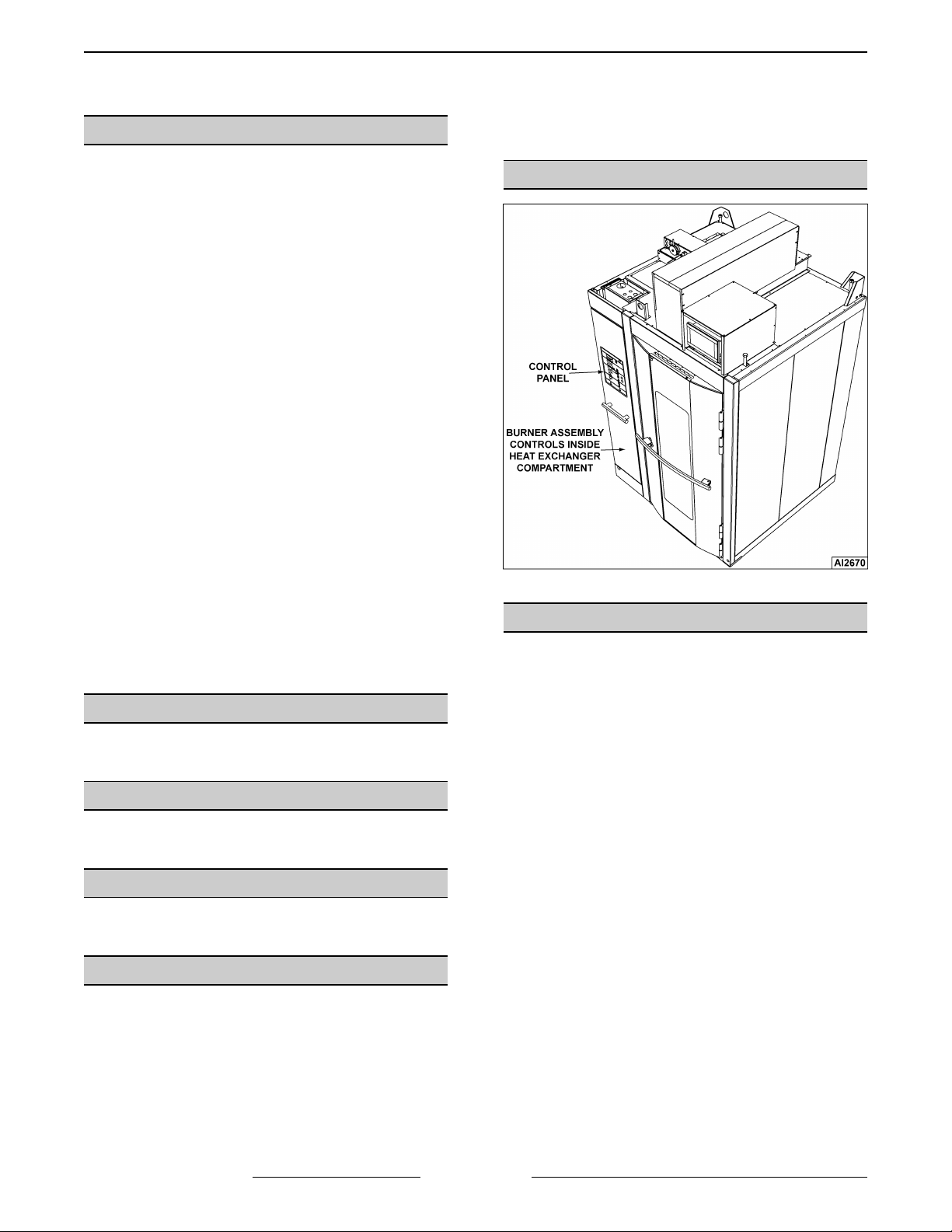
CONTROL LOCATION
Steaming System
Standard on all rack ovens, is a self-contained
spherical cast steam system providing excellent
steaming conditions.
LOCATION
Refer to the Installation Instructions for specific
location requirements.
OPERATION
Refer to the Operation Manual for specific operating
instructions.
CLEANING
Refer to the Operation Manual for specific cleaning
instructions.
LUBRICATION
• Circulation motor upper and lower bearings,
rotator chain, and lift motor spherical bearing
lubricate with high temperature grease every 6
months.
• Lift actuator.
• Oven has high temperature self-lubricating
TOOLS
• Standard set of hand tools
• Oven pressure panel feeler gauge Part No. 011M5689-1 Do not discard feeler gauge
• Multi-Meter that measures 200 micro amps
Grainger No. 6MR09
• Clamp meter Part No. 00-541069 Grainger No.
1ND81 or equivalent
• Temperature tester (thermocouple type) with 10'
probe
• Inclined manometer - Dwyer Cat. #1227 or
equivalent
• Manometer U tube Part No. TL-84908 or
equivalent
• Grounding kit - Static Control Kit Grainger No.
4KK44
• Jeweler's screw driver set - Sears No.
00930448000 or equivalent
• Combustion analyzer Bacharach Fyrite Pro 125
Bacharach model# 24-8105 or Fyrite "Insight"
Model 24-8251(Order from Bakery Support)
• BACHARACH gas leak detector (Order from
Bakery Support)
F25361 (January 2010)
Page 4 of 60
OV500 SERIES RACK OVEN - GENERAL
OV500G1 GAS OVEN
SPECIFICATIONS
â WATER:
1/2" NPT, 30-75 PSI cold water required, customer to
install in-line filter, shut off valve and line strainer.
Ï DRAIN:
6 1/4" (front) or 7" (rear) connection A.F.F. (See
notes). Route to air-gap drain. Do not slope drain
upwards. Plug the drain connection that is not in use.
Rear Drain: 1/2" NPTF
Front Drain: 1/2" NPTF
Ð POWER:
Two supplies required.
120/60/1 20 AMP dedicated circuit required and one
of the following voltage options.
Voltage Full Load AMPS
208 - 240/60/1 8.8 - 7.6 AMPS
208 - 240/60/3 5.0 - 4.4 AMPS
440 - 480/60/3 2.4 - 2.2 AMPS
Ñ GAS:
Natural Gas (N.G.)
3/4" NPT, W.C.N.G. (N.G. rated 1025 BTU/CU. FT.
SP. GR. 1.00)
Liquified Propane Gas (L.P.G.)
3/4" NPT, W.C.L.P.G. (L.P.G. rated 2440
BTU/CU.FT., SP. GR. 1.52)
Natural Gas Liquified Propane Gas
BTU/HR 180,000 180,000
W.C. 5.0" - 10.0" 12.0" - 14.0"
Ò HOOD VENT:
8" DIA connection collar. Customer to supply duct
and ventilator fan per state and local codes. Air
proving switch factory installed & integrated with
burner system operation. Oven provided relay with
max. 10 amp 1/2 H.P. @ 120V output for fan
operation. If larger, use oven relay to control
additional separately powered contactor / relay for
hood fan. Chamber vents are factory ducted to this
integral hood. 690 CFM required, 0.6" W.C. static
pressure drop through hood. Hood is UL710 Listed
when grease filters are installed. Type B gas vent
can be used except when bake products are grease
laden.
NOTES:
1. A.F.F.: Above finished floor.
2. Customer responsible to finish and install all utilities
to and from oven.
3. All services must comply with all Federal, State and
Local codes.
4. To reduce the risk of fire, the appliance is
to be installed on non-combustible surface only, with
no combustible material within 18 inches above the
appliance. The appliance is to be mounted on floors
of non-combustible construction with noncombustible flooring and surface finish and with no
combustible material against the underside, or on
non-combustible slabs or arches having no
combustible material against the underside. Such
construction shall in all cases extend not less than 12
inches beyond the equipment on all sides.
5. The floor must be of non-combustible material, and
must be level with surrounding area with a maximum
slope of 1/8" per foot up to 3/4" maximum in all
directions. Floor anchors require a minimum 1" thick
solid floor substrate.
6. Oven is UL/C-UL classified and CSA (AGA/CGA)
approved for 0" clearance on the side and rear walls.
Unit requires 1" to 4" clearance for rear drain
connection.
7. Top of oven requires a minimum of 24" for service
accessibility.
8. Customer responsible to install flue piping. Flue must
be vented outside of building.
9. Manufacturer reserves the right to make changes in
sizes and specifications.
Export Ratings
â WATER:
1/2" NPT, 2.1-5.2 Bar cold water required, customer
to install in-line filter, shut off valve and line strainer.
Flow rate of 8 l/min..
Ð POWER:
Single supply connection provided:
200V/50-60HZ/3PH/5.3A OR 380415V/50HZ/3PH/2.8-2.5 circuit required.
1 kVA transformer supplied for control circuit
operation voltage of 110V. This is a multifunction
transformer, so output voltage should be verified
before operation. Some wiring may be required to
obtain proper output voltage.
Oven fan (1.1kW) 200V/50-60Hz/3ph/5.3A or 380415V/50Hz/3ph/ 2.8 - 2.5A.
ÑGAS:
Natural Gas (N.G.)
3/4" NPT (N.G. Rated 38.2Mj/m3 or 9120 Kcal/m3
SP Gr 1.00)
Liquefied Propane Gas (LPG)
3/4" NPT (LPG Rated 90.9Mj/m3 or 21710 Kcal/m3
SP Gr 1.52)
Natural Gas Liquified Propane Gas
kCAL/HR 45,400 45,400
cm W.C. 12.7 - 25.4 30.5 - 35.6
Mj/HR 190 190
kPa 1.25 - 2.50 3.00 - 3.50
NOTE: Pressure not to exceed 35.6 cm W.C. or 3.5 kPa
Ò HOOD VENT:
20.3 cm DIA. Connection collar. Customer is to
supply duct and ventilator fan per federal and/or local
codes. Chamber vent (steam) and combustion
exhaust are discharged into the hood. An air proving
switch is factory installed and integrated with burner
system operation. If proper ventilation is not
provided, burner will not operate. Oven provides a
relay to activate a customer supplied and powered
contactor/relay, so that when oven is powered up
external fan will operate. The hood requires a
minimum of 19.5 m
3
/min for safe operation. For fan
calculation purposes you should assume 0.15 kPa
resistance through the hood. Grease filters (optional)
may be installed in the hood instead of standard
baffle.
F25361 (January 2010)Page 5 of 60

OV500 SERIES RACK OVEN - GENERAL
F25361 (January 2010) Page 6 of 60
OV500 SERIES RACK OVEN - GENERAL
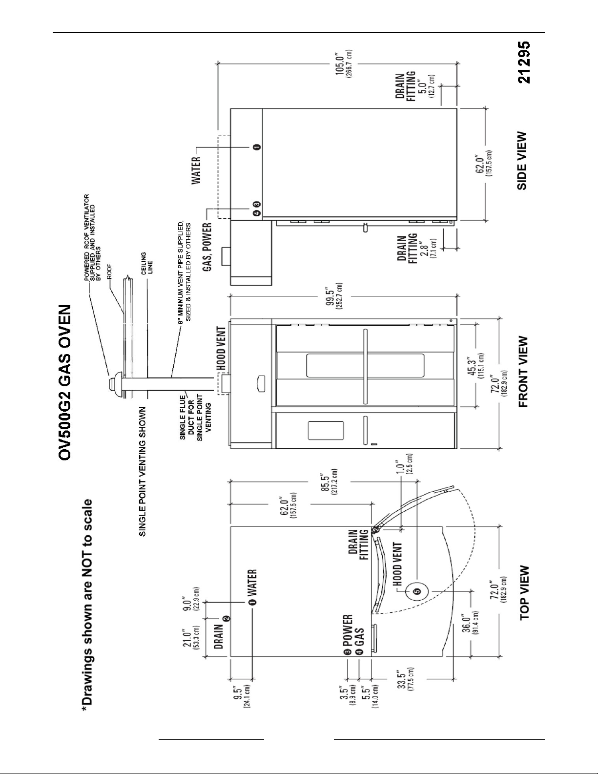
OV500G2 GAS OVEN
SPECIFICATIONS
â WATER:
1/2" NPT, 30-75 PSI cold water required, customer to
install in-line filter, shut off valve and line strainer.
Ï DRAIN:
2 3/4" (front) or 5 1/2" (rear) connection A.F.F. (See
notes). Route to air-gap drain. Do not slope drain
upwards. Plug the drain connection that is not in use.
Kit provided to extend drain to either side of oven.
Rear Drain: 3/4" NPTF
Front Drain: 3/8" NPTF
Ð POWER:
Two supplies required.
120/60/1 20 AMP dedicated circuit required and one
of the following voltage options.
Voltage Full Load AMPS
208 - 240/60/1 8.8 - 7.6 AMPS
208-240/60/3 5.0 - 4.4 AMPS
440 - 480/60/3 2.4 - 2.2 AMPS
Ñ GAS:
Natural Gas (N.G.)
1 1/4" NPT, W.C.N.G. (N.G. rated 1025 BTU/CU.
FT. SP. GR. 1.00)
Liquified Propane Gas (L.P.G.)
1 1/4" NPT, W.C.L.P.G. (L.P.G. rated 2440
BTU/CU.FT., SP. GR. 1.52)
Natural Gas Liquified Propane Gas
BTU/HR 300,000 350,000 300,000 350,000
W.C. 5.0 -14.0" 6.0 - 14.0" 10.0" - 14.0" 12.0 - 14.0"
Ò HOOD VENT:
10" DIA connection collar. Air proving switch factory
installed & integrated with burner system operation.
Oven provided rely with max. 10 amp 1/2 H.P. @
120V output for fan operation. If larger, use oven
relay to control additional separately powered
contactor / relay for hood fan. Customer to supply
duct and ventilator fan per state and local codes.
Chamber vents are factory ducted to this integral
hood. 900 CFM required, 0.6" W.C. static pressure
drop through hood. Hood is UL710 Listed when
grease filters are installed. Type B gas vent can be
used except when bake products are grease laden.
NOTES:
1. A.F.F.: Above finished floor.
2. Customer responsible to finish and install all utilities
to and from oven.
3. All services must comply with all Federal, State and
Local codes.
4. To reduce the risk of fire, the appliance is
to be installed on non-combustible surface only, with
no combustible material within 18 inches above the
appliance. The appliance is to be mounted on floors
of non-combustible construction with noncombustible flooring and surface finish and with no
combustible material against the underside, or on
non-combustible slabs or arches having no
combustible material against the underside. Such
construction shall in all cases extend not less than 12
inches beyond the equipment on all sides.
5. The floor must be of non-combustible material, and
must be level with surrounding area with a maximum
slope of 1/8" per foot up to 3/4" maximum in all
directions. Floor anchors require a minimum 1" thick
solid floor substrate.
6. Oven is UL/C-UL classified and CSA (AGA/CGA)
approved for 0" clearance on the side and rear walls.
Unit requires 1" to 4" clearance for rear drain
connection.
7. Top of oven requires a minimum of 24" for service
accessibility.
8. Customer responsible to install flue piping. Flue must
be vented outside of building.
9. Manufacturer reserves the right to make changes in
sizes and specifications.
Export Ratings
â WATER:
1/2” NPT, 2.1-5.2 Bar cold water required, customer
to install in-line filter, shut off valve and line strainer.
Flow rate of 8 l/min..
Ð POWER:
Single supply connection provided: 200V/5060Hz/3ph/5.3A or 380-415V/50Hz/3ph/ 2.8 - 2.5A
circuit required.
1 kVA transformer supplied for control circuit
operation voltage of 110V. This is a multifunction
transformer, so output voltage should be verified
before operation. Some wiring may be required to
obtain proper output voltage.
Oven fan (1.1kW) operates @ 380-415V 3ph 50 Hz
2.4- 2.2A
Ñ GAS:
Natural Gas (N.G.)
3/4” NPT (N.G. Rated 38.2Mj/m3 or 9120 Kcal/m3
SP Gr 1.00)
Liquefied Propane Gas (LPG)
3/4” NPT (LPG Rated 90.9Mj/m3 or 21710 Kcal/m3
SP Gr 1.52)
Natural Gas Liquified Propane Gas
kCAL/HR 75,600 75,600
cm W.C. 12.7 - 25.4 30.5 - 35.6
Mj/HR 317 317
kPa 1.25 - 3.50 3.00 - 3.50
NOTE: Pressure not to exceed 35.6 cm W.C. or 3.5 kPa
Ò HOOD VENT:
25.4 cm DIA. Connection collar. Customer is to
supply duct and ventilator fan per federal and/or local
codes. Chamber vent (steam) and combustion
exhaust are discharged into the hood. An air proving
switch is factory installed and integrated with burner
system operation. If proper ventilation is not
provided, burner will not operate. Oven provides a
relay to activate a customer supplied and powered
contactor/relay, so that when oven is powered up
external fan will operate. The hood requires a
minimum of 25.5 m
3
/min for safe operation. For fan
calculation purposes you should assume 0.15 kPa
resistance through the hood. Grease filters (optional)
may be installed in the hood instead of standard
baffle.
F25361 (January 2010)Page 7 of 60
OV500 SERIES RACK OVEN - GENERAL
F25361 (January 2010) Page 8 of 60
OV500 SERIES RACK OVEN - GENERAL
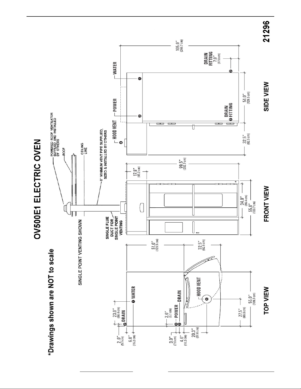
OV500E1 ELECTRIC OVEN
SPECIFICATIONS
â WATER:
1/2" NPT, 30-75 PSI cold water required, customer to
install in-line filter, shut off valve and line strainer.
Ï DRAIN:
6 1/4" (front) or 7" (rear) connection A.F.F. (See
notes). Route to air-gap drain. Do not slope drain
upwards. Plug the drain connection that is not in use.
Rear Drain: 1/2" NPTF
Front Drain: 1/2" NPTF
Ð POWER:
Two supplies required.
120/60/1 20 AMP dedicated circuit required and one
of the following voltage options.
Heating Circuit: KW rating in following chart per
supply voltage.
Blower Motor: 1 1/2 H.P.
Voltage Full Load AMPS Heaters Rating
208/60/3 100 AMPS 34 KW
208 - 240/60/3 76 - 87 AMPS 26 - 34 KW
440 - 480/60/3 40 - 43 AMPS 29 - 34 KW
Ñ HOOD VENT:
8" DIA connection collar. Customer to supply duct
and ventilator fan per state and local codes. Oven
provided relay with max. 10 amp 1/2 H.P. @ 120V
output for fan operation. If larger, use oven relay to
control additional separately powered contactor /
relay for hood fan. Chamber vents are factory ducted
to this integral hood. 690 CFM required, 0.6" W.C.
static pressure drop through hood. Hood is UL710
Listed when grease filters are installed. Type B gas
vent can be used except when bake products are
grease laden.
NOTES:
1. A.F.F.: Above finished floor.
2. Customer responsible to finish and install all utilities
to and from oven.
3. All services must comply with all Federal, State and
Local codes.
4. To reduce the risk of fire, the appliance is
to be installed on non-combustible surface only, with
no combustible material within 18 inches above the
appliance. The appliance is to be mounted on floors
of non-combustible construction with noncombustible flooring and surface finish and with no
combustible material against the underside, or on
non-combustible slabs or arches having no
combustible material against the underside. Such
construction shall in all cases extend not less than 12
inches beyond the equipment on all sides.
5. The floor must be of non-combustible material, and
must be level with surrounding area with a maximum
slope of 1/8" per foot up to 3/4" maximum in all
directions. Floor anchors require a minimum 1" thick
solid floor substrate.
6. Oven is UL/C-UL classified and CSA (AGA/CGA)
approved for 0" clearance on the side and rear walls.
Unit requires 1" to 4" clearance for rear drain
connection.
7. Top of oven requires a minimum of 24" for service
accessibility.
8. Customer responsible to install flue piping. Flue must
be vented outside of building.
9. Manufacturer reserves the right to make changes in
sizes and specifications.
Export Ratings
â WATER:
1/2” NPT, 2.1 - 5.2 Bar cold water required, customer
to install in-line filter, shut off valve and line strainer.
Flow rate of 8 l/min.
Ð POWER:
Single supply connection provided: 200V/5060Hz/3ph/5.3A or 380-415V/50Hz/3ph
circuit required.
1 kVA transformer supplied for control circuit
operation voltage of 110V. This is a multifunction
transformer, so output voltage should be verified
before operation. Some wiring may be required to
obtain proper output voltage.
Oven fan (1.1kW) operates @ 380-415V 3ph 50 Hz
2.4- 2.2A
Voltage Full Load AMPS Heaters Rating
200/50 - 60/3 74 AMPS 24 kW
380 - 415/50/3 46 - 50 AMPS 29 - 34 kW
Ñ HOOD VENT:
20.3 cm DIA. Connection collar. Customer is to
supply duct and ventilator fan per federal and/or local
codes. Chamber vent (steam) and combustion
exhaust are discharged into the hood. Oven provides
a relay to activate a customer supplied and powered
contactor/relay, so that when oven is powered up
external fan will operate. The hood requires a
minimum of 19.5 m
calculation purposes you should assume 0.15 kPa
resistance through the hood. Grease filters (optional)
may be installed in the hood instead of standard
baffle.
3
/min for safe operation. For fan
/ 2.8 - 2.5A
F25361 (January 2010)Page 9 of 60
OV500 SERIES RACK OVEN - GENERAL
F25361 (January 2010) Page 10 of 60
OV500 SERIES RACK OVEN - GENERAL
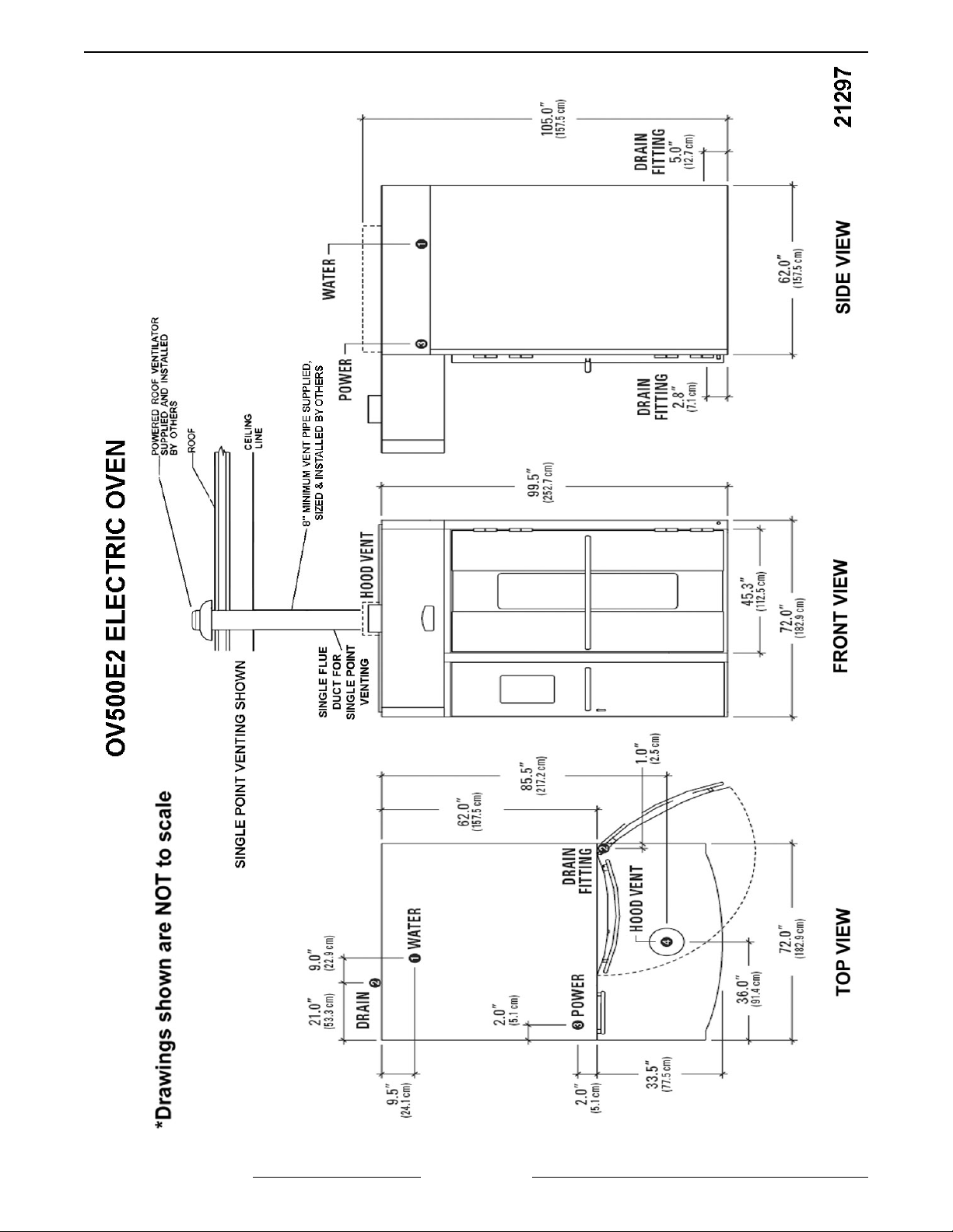
OV500E2 ELECTRIC OVEN
SPECIFICATIONS
â WATER:
1/2" NPT, 30-75 PSI cold water required, customer to
install in-line filter, shut off valve and line strainer.
Ï DRAIN:
2 3/4" (front) or 5 1/2" (rear) connection A.F.F. (See
notes). Route to air-gap drain. Do not slope drain
upwards. Plug the drain connection that is not in use.
Kit provided to extend drain to either side of oven.
Rear Drain: 3/4" NPTF
Front Drain: 3/8" NPTF
Ð ELECTRICAL:
Two supplies required.
120/60/1 20 AMP dedicated circuit required and one
of the following voltage options.
Heating Circuit: KW rating in following chart per
supply voltage.
Blower Motor: 1 1/2 H.P.
Voltage Full Load AMPS Heaters Rating
208/60/3 146.4 AMPS 51.3 KW
208-240/60/3 111.2 - 127.2 AMPS 38.5 - 51.3KW
440-480/60/3 59.1 - 64.1 AMPS 43 - 51.3 KW
Ñ HOOD VENT:
10"DIA connection collar. Customer to supply duct
and ventilator fan per state and local codes. Oven
provided relay with max. 10 amp 1/2 H.P. @ 120V
output for fan operation. If larger, use oven relay to
control additional separately powered contactor /
relay for hood fan. Customer to supply duct and
ventilator fan per state and local codes. Chamber
vents are factory ducted to this integral hood. 900
CFM required, 0.6" W.C. static pressure drop
through hood. Hood is UL710 Listed when grease
filters are installed. Type B gas vent can be used
except when bake products are grease laden.
NOTES:
1. A.F.F.: Above finished floor.
2. Customer responsible to finish and install all utilities
to and from oven.
3. All services must comply with all Federal, State and
Local codes.
4. To reduce the risk of fire, the appliance is
to be installed on non-combustible surface only, with
no combustible material within 18 inches above the
appliance. The appliance is to be mounted on floors
of non-combustible construction with noncombustible flooring and surface finish and with no
combustible material against the underside, or on
non-combustible slabs or arches having no
combustible material against the underside. Such
construction shall in all cases extend not less than 12
inches beyond the equipment on all sides.
5. The floor must be of non-combustible material, and
must be level with surrounding area with a maximum
slope of 1/8" per foot up to 3/4" maximum in all
directions. Floor anchors require a minimum 1" thick
solid floor substrate.
6. Oven is UL/C-UL classified and CSA (AGA/CGA)
approved for 0" clearance on the side and rear walls.
Unit required 1" to 4" clearance for rear drain
connection.
7. Top of oven requires a minimum of 24" for service
accessibility.
8. Customer responsible to install flue piping. Flue must
be vented outside of building.
9. Manufacturer reserves the right to make changes in
sizes and specifications.
Export Ratings
â WATER:
1/2" NPT, 2.1-5.2 Bar cold water required, customer
to install in-line filter, shut off valve and line strainer.
Flow rate of 8 l/min..
Ð ELECTRICAL:
Single supply connection provided: 200V/5060Hz/3ph/5.3A or 380-415V/50Hz/3ph
circuit required.
1 kVA transformer supplied for control circuit
operation voltage of 110V. This is a multifunction
transformer, so output voltage should be verified
before operation. Some wiring may be required to
obtain proper output voltage.
Oven fan (1.1kW) operates @ 380-415V 3ph 50 Hz
2.4- 2.2A
Voltage Full Load AMPS Heaters Rating
200/50 - 60/3 108 AMPS 36 kW
380 - 415/50/3 68 - 73 AMPS 43 - 51 kW
Ñ HOOD VENT:
25.4 cm DIA. Connection collar. Customer is to
supply duct and ventilator fan per federal and/or local
codes. Chamber vent (steam) and combustion
exhaust are discharged into the hood. Oven provides
a relay to activate a customer supplied and powered
contactor/relay, so that when oven is powered up
external fan will operate. The hood requires a
minimum of 25.5 m
calculation purposes you should assume 0.15 kPa
resistance through the hood. Grease filters (optional)
may be installed in the hood instead of standard
baffle.
3
/min for safe operation. For fan
/ 2.8 - 2.5A
F25361 (January 2010)Page 11 of 60
OV500 SERIES RACK OVEN - GENERAL
F25361 (January 2010) Page 12 of 60

OV500 SERIES RACK OVEN - REMOVAL AND REPLACEMENT OF PARTS
REMOVAL AND REPLACEMENT OF PARTS
STEAM PANEL
NOTE: Hand tighten only, do not use power tools
when installing panel screws.
1. Remove screws securing steam panel to baking
compartment rear wall (through access holes).
4. Reverse the procedure to install.
RACK ROTATOR ASSEMBLY
2. Remove screws securing steam panel to left
baking compartment wall.
Removal
1. Remove rack carrier.
A. Support rack carrier.
B. Loosen set screws.
C. Remove snap ring from end of shaft.
D. Lower carrier to remove.
2. Remove rotator and lift assembly cover.
3. Remove actuator for rack up and down
switches.
4. Disconnect lead wires from rack pointer
switches, capacitor, and rotator motor.
3. Remove screws securing steam panel to baking
compartment ceiling (left rear corner) Reverse
the procedure to install.
F25361 (January 2010)Page 13 of 60
OV500 SERIES RACK OVEN - REMOVAL AND REPLACEMENT OF PARTS
5. Lift rack rotator assembly, which will include the
rack lift shaft, from rack lift assembly.
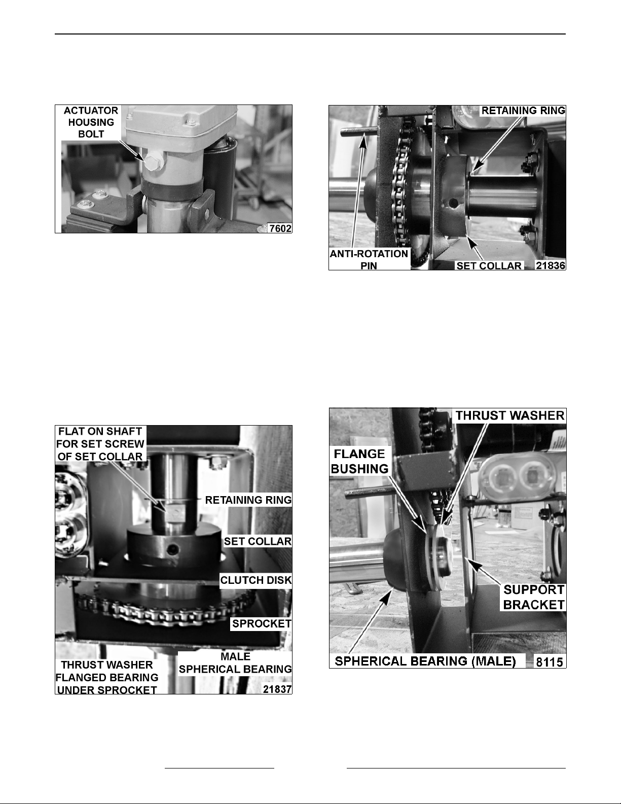
NOTE: Removal of actuator housing bolt may be
necessary for rack rotator assembly removal.
Disassembly
1. Loosen set screw and remove rack pointer from
shaft.
2. Loosen set screws securing the set collar to
rotator shaft.
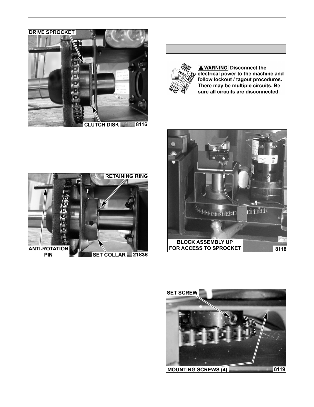
3. Remove the retaining ring from groove in rotator
shaft.
NOTE: Remove retaining ring from shaft as you are
removing shaft from assembly.
4. Pull rotator shaft from rotator assembly set
collar, clutch disk, drive sprocket, thrush
washer, flanged bearing and male half of
spherical bearing.
lift arm only if replacing.
Assembly
1. Install female half of spherical bearing into the
lift arm if removed.
2. Apply high temperature grease to female half of
spherical bearing. Spread grease evenly across
bearing surface.
3. Install flange bushing into rotator assembly.
4. Install male half of spherical bearing, with taper
to mate with female half, onto flanged bushing.
5. Insert rotator shaft into flange bushing from
bottom of rotator assembly and install thrust
washer.
5. Remove rotator drive chain from sprocket teeth.
6. Remove flange bushing from rotator bracket.
7. Remove female half of spherical bearing from
F25361 (January 2010)
Page 14 of 60
6. Install drive chain around drive sprocket.
7. Continue to push the shaft through the rotator
assembly. As you do, install drive sprocket onto
shaft (tooth side towards thrush washer) before
the shaft is beyond the support bracket.
OV500 SERIES RACK OVEN - REMOVAL AND REPLACEMENT OF PARTS
8. Install clutch disk.
9. Install set collar with counter bore edge towards
clutch and slide split ring onto shaft.
A. Position set collar so set screw can be
secured onto flat of rack lift shaft.
10. Install retaining ring into groove of rotator shaft.
SERVICE PROCEDURES AND
ADJUSTMENTS.
19. Check for proper operation.
ROTATOR MOTOR
Removal
1. Block the rack rotator assembly in a position to
access the motor mounting bolts and sprocket
set screw.
11. Insert rotator shaft through female half of
spherical bearing in lift arm.
12. Apply high temperature grease to drive chain.
13. Lower rotator assembly. Rotator shaft will align
with bearings in rotator shaft housing.
NOTE: Anti rotation pin on rotator assembly must
mate with anti rotation slot in lift arm.
14. If removed earlier, install actuator housing
screw and actuator for rack up and down
switches.
15. Install rack pointer onto rotator shaft.
16. Install rack carrier.
17. Adjust RACK POINTER as outlined under
SERVICE PROCEDURES AND
ADJUSTMENTS.
18. Adjust RACK HEIGHT as outlined under
2. Disconnect the rotator motor lead wires.
3. Remove cooling fan from motor.
4. Loosen rotator motor sprocket set screw.
5. Remove rotator motor mounting screws.
6. Lift rotator motor and sprocket will stay in place.
F25361 (January 2010)Page 15 of 60
OV500 SERIES RACK OVEN - REMOVAL AND REPLACEMENT OF PARTS
Assembly
1. Install rotator motor shaft through rotator
assembly and rotator sprocket.
2. Position sprocket onto rotator motor shaft, collar
side towards motor.
3. Install rotator motor mounting screws and align
sprocket and rotator drive chain. Ensure rotator
drive chain is not in a bind.
4. Secure set screw onto motor shaft.
5. Connect rotator motor lead wires.
NOTE: Shaft rotation viewed from top of oven.
Clockwise Rotation: Red wire= #20, Black wire=
#53, White/White wires, recommended.
6. Install cooling fan to motor shaft.
7. Remove block from rotator assembly.
8. Check for proper operation.
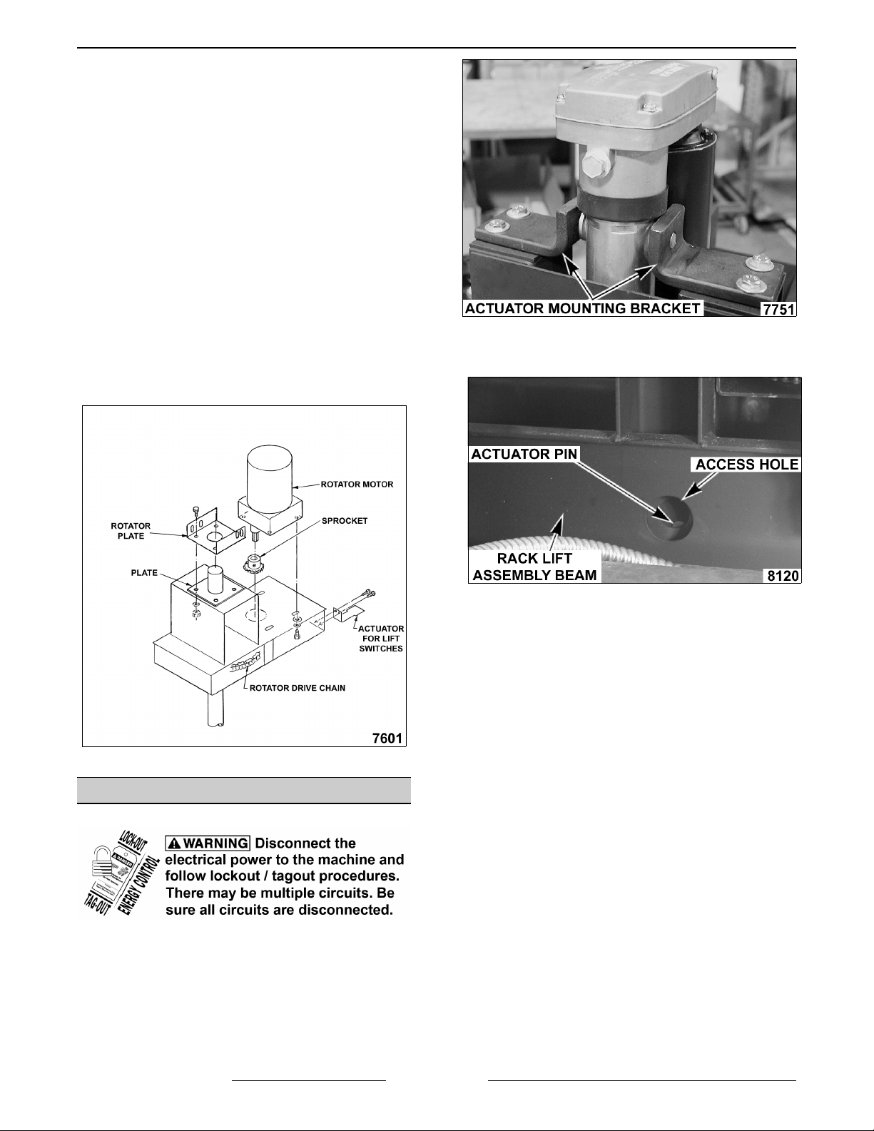
4. Align bottom actuator arm pin with access hole
in side of rack lift assembly beam.
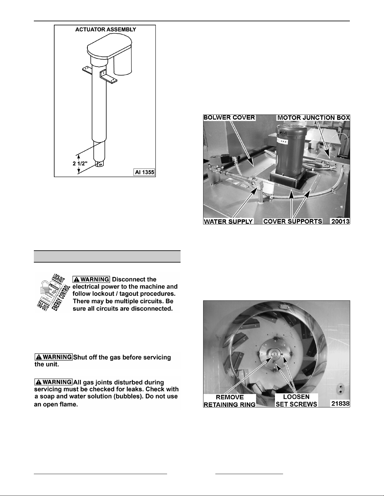
ACTUATOR
1. Block the rack rotator assembly from moving.
2. Disconnect lead wires to actuator motor.
3. Remove top actuator mounting brackets from
rack lift assembly.
5. Block rack lift arm to prevent movement.
6. Remove actuator pin from the assembly and
remove actuator from rack lift assembly.
7. Make sure replacement actuator is fully
retracted. Turn end of actuator arm CCW 12
complete turns.
NOTE: Measure end of actuator arm to bottom of
actuator arm housing, measurement should be
approximately 2 1/2".
F25361 (January 2010) Page 16 of 60
OV500 SERIES RACK OVEN - REMOVAL AND REPLACEMENT OF PARTS
8. Install lower actuator arm pin through lift pin.
1. If necessary, move the gas line out of the way.
2. Shut off water supply line and remove exterior
water supply that is within the boundary of
blower cover.
3. Disconnect lead wires at motor junction box.
4. Remove motor junction box.
5. Remove probe cover and any existing probes.
6. Remove blower cover supports.
7. Remove blower cover.
9. Position the rack rotator assembly so the top
actuator mounting brackets will align with the
rotator assembly.
10. Reconnect lead wires.
11. Put oven into use and check for proper
operation.
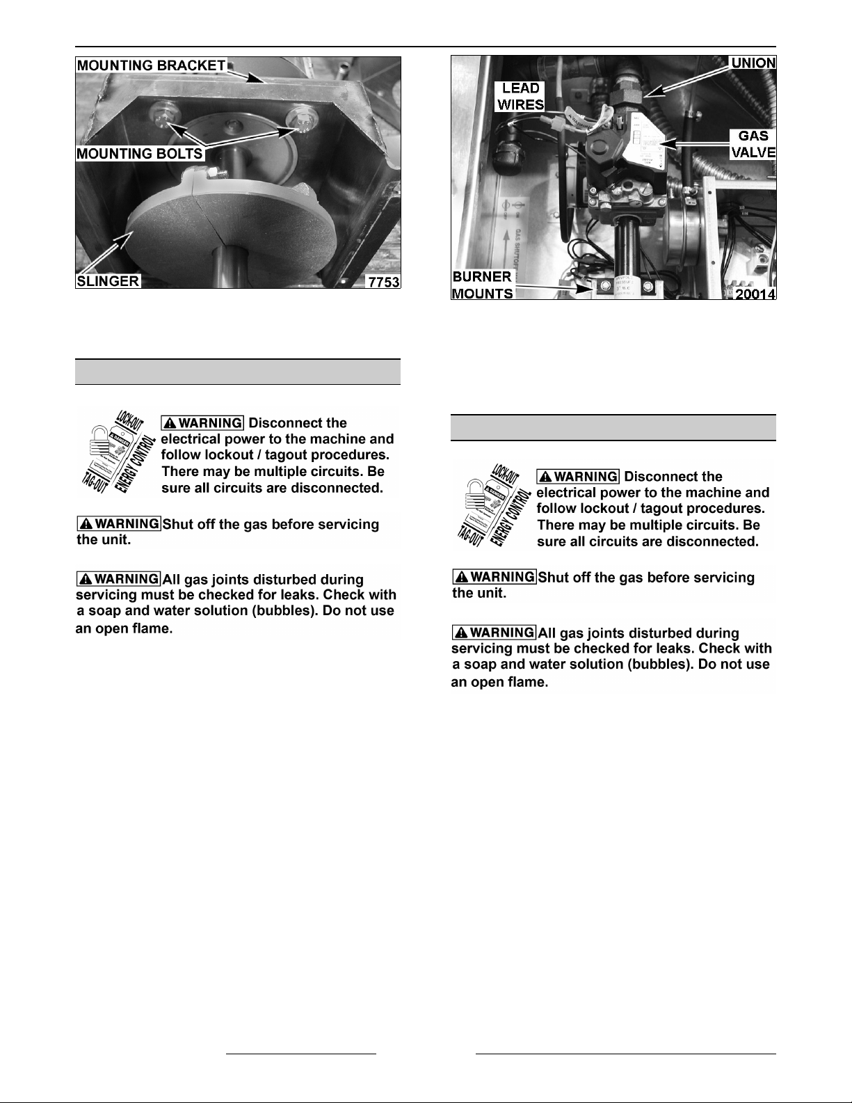
CONVECTION BLOWER/MOTOR
NOTE: To follow this procedure, there must be 24''
of clearance at the top of the oven. If not, the blower
wheel must be accessed thru the heat exchanger
compartment.
8. Remove insulation.
9. Remove screws from blower mounting
assembly and remove complete blower
assembly.
10. Loosen set screws in blower wheel hub.
11. Remove retaining ring from shaft.
12. Remove blower wheel from motor shaft.
A. CHECK ALL JOINTS PRIOR TO THE
GAS VALVE (SOLENOID) BEFORE
LIGHTING UNIT.
B. CHECK ALL JOINTS AFTER TO THE
GAS VALVE (SOLENOID) AFTER THE
UNIT IS LIT.
13. Remove screws securing motor mounting
bracket and remove motor assembly.
F25361 (January 2010)Page 17 of 60
OV500 SERIES RACK OVEN - REMOVAL AND REPLACEMENT OF PARTS
14. Remove heat slinger and mounting bracket
from motor.
4. Reverse procedure to install.
15. Reverse the procedure to install.
GAS VALVE
A. CHECK ALL JOINTS PRIOR TO THE
GAS VALVE (SOLENOID) BEFORE
LIGHTING UNIT.
B. CHECK ALL JOINTS AFTER TO THE
GAS VALVE (SOLENOID) AFTER THE
UNIT IS LIT.
1. Open control compartment door to gain access
to gas manifold assembly.
2. Disconnect the gas supply union fitting from gas
manifold assembly.
NOTE: The burner mounts may have to be loosened
to allow the gas valve to rotate.
3. Remove the valve from the burner manifold.
5. Check GAS PRESSURE as outlined under
SERVICE PROCEDURES AND
ADJUSTMENTS.
6. Operate oven and check for proper operation.
GAS MANIFOLD / ORIFICES
A. CHECK ALL JOINTS PRIOR TO THE
GAS VALVE (SOLENOID) BEFORE
LIGHTING UNIT.
B. CHECK ALL JOINTS AFTER TO THE
GAS VALVE (SOLENOID) AFTER THE
UNIT IS LIT.
1. Open control compartment door to gain access
to gas manifold assembly.
2. Disconnect lead wires to gas valve, ignitor and
flame sensor.
3. Loosen the gas supply union fitting from gas
manifold assembly.
F25361 (January 2010) Page 18 of 60
 Loading...