


Hobart LX18C, LX40C, LX30H, LX30C, LX18 User Manual
...
I
N
S
T
LX SERIES DISHWASHERS
MODELS
LX18 ML-104349
LX18C ML-104350
LX18H ML-104351
LX30 ML-104352
LX30C ML-104353
LX30H ML-104354
LX40C ML-104355
LX40H ML-104356
R
LX SERIES DISHWASHER
U
C
T
I
O
N
S
701 S. RIDGE AVENUE
TROY, OHIO 45374-0001
937 332-3000
www.hobartcorp.com
FORM 18615 Rev. I (July 2000)

TABLE OF CONTENTS
GENERAL. . . . . . . . . . . . . . . . . . . . . . . . . . . . . . . . . . . . . . . . . . . . . . . . . . . . . . . . . . . . . . . . . . . . . 3
INSTALLATION . . . . . . . . . . . . . . . . . . . . . . . . . . . . . . . . . . . . . . . . . . . . . . . . . . . . . . . . . . . . . . . . 4
Unpacking. . . . . . . . . . . . . . . . . . . . . . . . . . . . . . . . . . . . . . . . . . . . . . . . . . . . . . . . . . . . . . . . . . 4
Trim Strip Accessory Kit . . . . . . . . . . . . . . . . . . . . . . . . . . . . . . . . . . . . . . . . . . . . . . . . . . . . . . 4
Location . . . . . . . . . . . . . . . . . . . . . . . . . . . . . . . . . . . . . . . . . . . . . . . . . . . . . . . . . . . . . . . . . . . 4
Leveling . . . . . . . . . . . . . . . . . . . . . . . . . . . . . . . . . . . . . . . . . . . . . . . . . . . . . . . . . . . . . . . . . . . 4
Water Requirements . . . . . . . . . . . . . . . . . . . . . . . . . . . . . . . . . . . . . . . . . . . . . . . . . . . . . . . . . 4
Plumbing Connections. . . . . . . . . . . . . . . . . . . . . . . . . . . . . . . . . . . . . . . . . . . . . . . . . . . . . . . . 5
Drain . . . . . . . . . . . . . . . . . . . . . . . . . . . . . . . . . . . . . . . . . . . . . . . . . . . . . . . . . . . . . . . . . . . . . . 5
Water Supply . . . . . . . . . . . . . . . . . . . . . . . . . . . . . . . . . . . . . . . . . . . . . . . . . . . . . . . . . . . . . . . 5
Electrical Connection . . . . . . . . . . . . . . . . . . . . . . . . . . . . . . . . . . . . . . . . . . . . . . . . . . . . . . . . . 6
Detergent and Rinse Aid . . . . . . . . . . . . . . . . . . . . . . . . . . . . . . . . . . . . . . . . . . . . . . . . . . . . . . 8
Chemical Sanitizer (Models LX18C, LX30C and LX40C Only). . . . . . . . . . . . . . . . . . . . . . . . 8
Installation Diagram (LX18, LX18C & LX18H) . . . . . . . . . . . . . . . . . . . . . . . . . . . . . . . . . . . . . 9
Installation Diagram (LX30, LX30C & LX30H) . . . . . . . . . . . . . . . . . . . . . . . . . . . . . . . . . . . . 10
Installation Diagram (LX40C & LX40H) . . . . . . . . . . . . . . . . . . . . . . . . . . . . . . . . . . . . . . . . . 11
OPERATION . . . . . . . . . . . . . . . . . . . . . . . . . . . . . . . . . . . . . . . . . . . . . . . . . . . . . . . . . . . . . . . . . 12
Before First Use . . . . . . . . . . . . . . . . . . . . . . . . . . . . . . . . . . . . . . . . . . . . . . . . . . . . . . . . . . . . 12
Controls — Models LX18, LX18C, LX18H, LX30, LX30C, and LX30H . . . . . . . . . . . . . . . . 12
Operating Models LX18, LX18C, LX18H, LX30, LX30C, and LX30H. . . . . . . . . . . . . . . . . . 13
Diagnostic Messages. . . . . . . . . . . . . . . . . . . . . . . . . . . . . . . . . . . . . . . . . . . . . . . . . . . . . 14
Models LX18, LX18C & LX18H . . . . . . . . . . . . . . . . . . . . . . . . . . . . . . . . . . . . . . . . . . . . . . . . 14
Modified Fill and Dump . . . . . . . . . . . . . . . . . . . . . . . . . . . . . . . . . . . . . . . . . . . . . . . . . . . 14
Modified Fill and Dump — Wash/Rinse Cycle Times . . . . . . . . . . . . . . . . . . . . . . . . . . . 14
True Fill and Dump. . . . . . . . . . . . . . . . . . . . . . . . . . . . . . . . . . . . . . . . . . . . . . . . . . . . . . . 14
True Fill and Dump — Wash/Rinse Cycle Times. . . . . . . . . . . . . . . . . . . . . . . . . . . . . . . 14
Models LX30, LX30C, and LX30H — Wash/Rinse Cycle Times . . . . . . . . . . . . . . . . . . . . . 15
Controls — Models LX40H & LX40C . . . . . . . . . . . . . . . . . . . . . . . . . . . . . . . . . . . . . . . . . . . 16
Operating Models LX40H & LX40C . . . . . . . . . . . . . . . . . . . . . . . . . . . . . . . . . . . . . . . . . . . . 16
Ready Mode . . . . . . . . . . . . . . . . . . . . . . . . . . . . . . . . . . . . . . . . . . . . . . . . . . . . . . . . . . . . 17
Diagnostic Messages. . . . . . . . . . . . . . . . . . . . . . . . . . . . . . . . . . . . . . . . . . . . . . . . . . . . . 18
Models LX40H & LX40C — Wash/Rinse Cycle Times . . . . . . . . . . . . . . . . . . . . . . . . . . 18
Operator Programming . . . . . . . . . . . . . . . . . . . . . . . . . . . . . . . . . . . . . . . . . . . . . . . . . . . 18
Priming Chemical Pumps . . . . . . . . . . . . . . . . . . . . . . . . . . . . . . . . . . . . . . . . . . . . . . . . . 18
Delime Cycle . . . . . . . . . . . . . . . . . . . . . . . . . . . . . . . . . . . . . . . . . . . . . . . . . . . . . . . . . . . 18
Manager Programming . . . . . . . . . . . . . . . . . . . . . . . . . . . . . . . . . . . . . . . . . . . . . . . . . . . 19
Programmable Variables and Recommended Settings — Models LX40H & LX40C. . . 20
Preparation — All Models . . . . . . . . . . . . . . . . . . . . . . . . . . . . . . . . . . . . . . . . . . . . . . . . . . . . 20
DOs and DON’Ts For Your New Hobart Warewasher. . . . . . . . . . . . . . . . . . . . . . . . . . . . . . 21
Cleaning — All Models . . . . . . . . . . . . . . . . . . . . . . . . . . . . . . . . . . . . . . . . . . . . . . . . . . . . . . 22
MAINTENANCE . . . . . . . . . . . . . . . . . . . . . . . . . . . . . . . . . . . . . . . . . . . . . . . . . . . . . . . . . . . . . . . 23
Deliming — General. . . . . . . . . . . . . . . . . . . . . . . . . . . . . . . . . . . . . . . . . . . . . . . . . . . . . . . . . 23
Deliming — Models LX18, LX18C & LX18H. . . . . . . . . . . . . . . . . . . . . . . . . . . . . . . . . . . . . . 23
Deliming — Models LX30, LX30C & LX30H. . . . . . . . . . . . . . . . . . . . . . . . . . . . . . . . . . . . . . 24
Deliming — Models LX40H & LX40C . . . . . . . . . . . . . . . . . . . . . . . . . . . . . . . . . . . . . . . . . . . 25
Lubrication . . . . . . . . . . . . . . . . . . . . . . . . . . . . . . . . . . . . . . . . . . . . . . . . . . . . . . . . . . . . . . . . 25
TROUBLESHOOTING. . . . . . . . . . . . . . . . . . . . . . . . . . . . . . . . . . . . . . . . . . . . . . . . . . . . . . . . . . 26
© HOBART CORPORATION, 1993
– 2 –
Installation, Operation, and Care of
LX SERIES DISHWASHERS
SAVE THESE INSTRUCTIONS
GENERAL
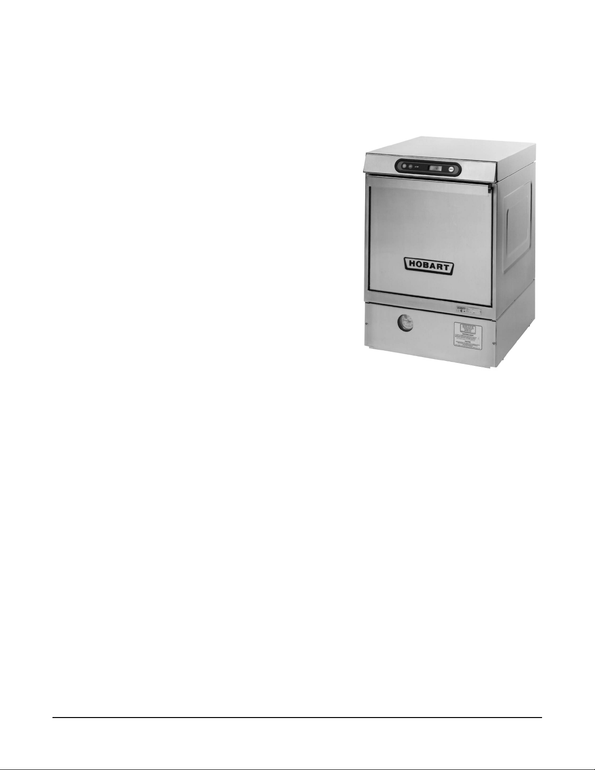
The LX Series dishwashers are fully automatic, front-loading
dishwashing machines which are equipped with a
horsepower electric motor.
All LX Series dishwashers shut down automatically four hours
after last use to conserve energy.
Standard equipment includes two 20" x 20" racks, electronic
controls, pumped drain, fill hose and drain hose.
MODEL DESCRIPTION
LX18H Washes with water from previous
rinse cycle, drains, and fills again with
fresh water for the rinse cycle. Rinse
is retained for the next wash cycle.
The LX18H has a built-in booster
heater.
LX18, LX18C Fill and drain cycle: fills, washes, drains, fills, rinses, and drains again to end
the cycle.
• LX18 requires 180°F incoming water temperature.
• LX18C is a low-temperature, chemical sanitizing machine for use with
or 8.40% sodium hypochlorite solution (bleach) as the sanitizing
3
/
4
Model LX30 Dishwasher
5.25%
agent.
LX30 Fresh water rinse; requires 180°F incoming water temperature.
LX30H, LX40H
LX30C, LX40C Fresh water rinse; low temperature, chemical sanitizing models for use
Water usage for the LX18 models is 2.6 gallons per rack (5.2 gallons per rack if the sump water
temperature cools between cycles); water usage for the LX30 and the LX40 models is 1.2 gallons per
rack. The machine uses 2.2 gallons per rack for the extended rinse cycle (available on LX40 models
in the heavy wash cycle only).
Fresh water rinse with a built-in booster heater. Normally the machine
requires 140°F incoming water and is heated in the booster to 180°F;
however, in the LX40H, a 70°F rise in temperature is available by using the
standard heavy cycle. This allows an incoming water temperature of
the LX30H, a 70°F rise is also possible; contact your local
Office.
5.25% or 8.40% sodium hypochlorite solution (bleach) as the
agent. LX30C equipped with electric booster water heater has 100°F minimum
water supply heated to 140°F with bleach as the sanitizing agent.
– 3 –
Hobart Service
110°F. In
with
sanitizing

INSTALLATION
UNPACKING
Immediately after unpacking the dishwasher, check for possible shipping damage. If this machine is
found to be damaged, save packaging material and contact the carrier within 15 days of delivery.
Prior to installation, verify that the electrical supply agrees with the specifications on the machine data
plate.
TRIM STRIP ACCESSORY KIT (Optional)
If you ordered the trim strip accessory kit, it must be installed prior to positioning the dishwasher.
To install the trim strip, remove the protective paper from the pressure-sensitive adhesive strip.
Carefully align trim strip with front edge and both sides of top cover and secure in place by firmly
pressing trim strip down against top cover.
LOCATION
Steam generated from normal operation may escape from the door. Wood, laminates, veneers, etc.
are unsuitable materials for use in areas exposed to dishwasher steam and detergents. Stainless steel
or other moisture resistant shields are recommended for surfaces adjacent to LX sides and top.
LEVELING
The machine must be level to operate properly. Place the dishwasher in its operating location. Level
the machine before any connections are made. Using a carpenter's level placed diagonally on the rack
tracks, level the machine front-to-back and side-to-side by threading the adjustable feet in or out. After
leveling the machine, cover the exposed threads of the adjustable feet with black rubber tubing
supplied (see separate instructions furnished with machine).
WATER REQUIREMENTS
Proper water quality can improve ware washing performance by reducing spotting, lowering chemical
supply costs, enhancing effectiveness of labor, and extending equipment life. Local water conditions
vary from one location to another. The recommended proper water treatment for effective and efficient
use of this equipment will also vary depending on the local water conditions. Ask your municipal water
supplier for details about local water specifics prior to installation.
Recommended water hardness is 4 – 6 grains of hardness per gallon. Chlorides must not exceed 50
parts per million. Water hardness above 6 grains per gallon should be treated by a water conditioner
(water softener or in-line treatment). Water hardness below 4 grains per gallon also requires
treatment to reduce potential corrosion. Water treatment has been shown to reduce costs associated
with machine cleaning, reduce deliming of the dishwasher, reduce detergent usage, and reduce
corrosion of metallic surfaces in the booster water heater and dishwasher.
Sediment, silica, chlorides, or other dissolved solids may lead to a recommendation for particulate
filtration or reverse osmosis treatment.
Water
If an inspection of the dishwasher or booster heater reveals lime build-up after the equipment has been
in service, in-line treatment should be considered, and, if recommended, should be installed and used
as directed. Contact your local Hobart Service Office for specific recommendations.
– 4 –

PLUMBING CONNECTIONS
WARNING: PLUMBING CONNECTIONS MUST COMPLY WITH APPLICABLE SANITARY, SAFETY,
AND PLUMBING CODES.
Drain
3
A drain hose is provided with a
/4" pipe connection adapter. This should be securely plumbed into the
sink drain. Use care not to kink hose. See installation diagrams in this manual. Drain must have a
minimum flow capacity of 10 gallons per minute.
Water Supply
A water hammer arrestor (meeting ASSE-1010 Standard or equivalent) should be installed (supplied
by others) in the common water supply line at the service connection.
Water must be proper hardness. Recommended hardness range is 4 – 6 grains per gallon. Lower
hardness can promote corrosion, higher hardness may cause excessive formation of lime scale.
The plumber who connects this machine is responsible for making certain that water lines are
THOROUGHLY FLUSHED OUT BEFORE connecting to the dishwasher. This "flush-out" is necessary
to remove all foreign matter, such as chips (resulting from cutting or threading of pipes), pipe joint
compound from the lines, or, if soldered fittings are used, bits of solder or cuttings from the tubing.
Debris, if not removed, may lodge in the dishwasher's plumbing components and render them
inoperative. Manual valves or solenoid valves fouled by foreign matter, and any expenses resulting
from this fouling, are NOT the responsibility of the manufacturer.
Water supply requirements are as follows:
MODEL TEMPERATURE FLOWING PRESSURE
LX18, LX30 180°F Minimum 15 to 25 psig
LX18H, LX30H, LX40H 140°F Minimum 15 to 25 psig
LX18C, LX30C, LX40C 140°F Minimum 15 to 25 psig
LX30C w/booster 100°F Minimum 15 to 25 psig
If flowing pressure exceeds 25 psig, a pressure reducing valve (not supplied) must be installed in the
supply line. CAUTION: The water pressure regulator must have a relief by-pass. Failure to use
the proper type of pressure regulator may result in damage to the unit. If flowing pressure is less
than 15 psig, improper machine operation may result.
A manual shutoff valve (not supplied) should be installed upstream of the fill hose to accommodate
servicing the machine.
It is recommended that a line strainer (not supplied) be installed in the supply line between the manual
shutoff valve (not supplied) and the connection point on the machine. Make plumbing connections with
1
/2" minimum copper piping OD (3/4" recommended), with a 3/4" male garden hose fitting (not supplied).
See installation diagrams, pages 9-11.
NOTE: Iron in the water supply can cause staining. An iron filter is recommended for iron concentration
greater than 0.1 part per million. High chloride levels in the water supply can cause pitting. A chloride
removal system is required if levels exceed 50 parts per million.
– 5 –

ELECTRICAL CONNECTION
WARNING: ELECTRICAL AND GROUNDING CONNECTIONS MUST COMPLY WITH THE
APPLICABLE PORTIONS OF THE NATIONAL ELECTRICAL CODE AND/OR OTHER LOCAL
ELECTRICAL CODES.
WARNING: DISCONNECT ELECTRICAL POWER SUPPLY AND PLACE A TAG AT THE
DISCONNECT SWITCH TO INDICATE THAT YOU ARE WORKING ON THE CIRCUIT.
ATADLACIRTCELE ◊◊◊◊◊
yticapmAtiucriCmuminiMyticapmAtiucriCmuminiM
yticapmAtiucriCmuminiMyticapmAtiucriCmuminiM
◊ .noitidetsetal,07-APFN,edoClacirtcelElanoitaNehthtiwecnadroccanidelipmoC
ledoMledoM
ledoMledoMesahP/ztreH/stloVesahP/ztreH/stloV
ledoM
81XL
C81XL
H81XL
)retsoobhtiw(
03XL
C03XL
C04XL
C03XL
)retsoobhtiw(
H03XL
)retsoobhtiw(
H04XL
)retsoobhtiw(
yticapmAtiucriCmuminiM
esahP/ztreH/stloVesahP/ztreH/stloV
esahP/ztreH/stloV
SPMASPMA
SPMASPMA
SPMA
eciveDevitcetorPmumixaMeciveDevitcetorPmumixaM
eciveDevitcetorPmumixaMeciveDevitcetorPmumixaM
eciveDevitcetorPmumixaM
eziSeriWeziSeriW
eziSeriWeziSeriW
eziSeriW
1/06/0210221
1/06/802
1/06/042
5141
1/06/802
*1/06/)W3(802/021
1/06/042
058
*1/06/)W3(042/021
3/06/802
3/06/042
038
3/06/004-0830221
3/06/0845141
1/06/021
1/06/802
*1/06/)W3(802/021
0221
1/06/042
*1/06/)W3(042/021
*1/06/)W3(802/021
*1/06/)W3(042/021
058
1/06/802
*1/06/)W3(802/021
1/06/042
058
*1/06/)W3(042/021
3/06/802048
3/06/042538
3/06/004-083
3/06/084
.dnuorgenihcamrofdedivorpebtsum
0221
reppoCdednartSC°09reppoCdednartSC°09
reppoCdednartSC°09reppoCdednartSC°09
reppoCdednartSC°09
eriwhtruoflanoitiddanA.lartuengniyrractnerrucaedulcnihcihwseriwrewopeerhteriuqersmetsys)W3(ehT*
– 6 –
Refer to the data plate on the front of the machine and the label inside the control drawer at the power
connection for proper selection.
Use stranded copper wire only.
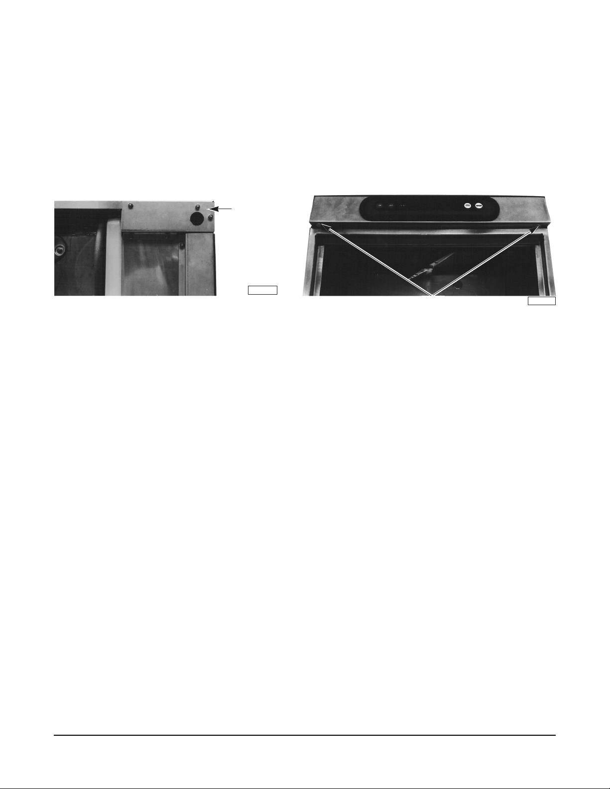
1. Remove the cover plate at the upper right in the back of the machine (Fig. 1). A hole for 1" trade
size conduit is supplied in the cover plate.
Cover Plate
PL-40805-1
Screws
Fig. 1 Fig. 2
PL-40163-1
2. Open dishwasher door and remove the 2 screws (Fig. 2) securing the controls drawer. Close the
dishwasher door and open the controls drawer fully.
3. Install 1" trade conduit and fitting to the cover plate. A 90° fitting is recommended.
4. Feed wires over top of tank to strain relief(s) at rear of drawer. At least 32" and not more than 36"
of the required wire size must extend from the end of the conduit fitting.
5. Reinstall the cover plate (3 screws, Fig. 1).
6. For 8 AWG wire, run no more than 2 wires through any strain relief (two strain reliefs are provided).
Make electrical connections per the wiring diagram supplied with the machine, and secure wires
to power terminal block and ground.
For 12 or 14 AWG wire, run 3 wires (or 4 wires if required) through the strain relief provided by
Hobart. Make electrical connections per the wiring diagram supplied with the machine. Secure
wires to the power terminal block and ground. Keep excess wire in the drawer to a minimum.
7. Tighten the set screw on the strain relief(s) until they bottom out (on the shoulder of the body).
8. Close the control drawer and replace the screws.
– 7 –

DETERGENT AND RINSE AID
If manually adding detergent in an LX18, LX18C, or LX18H at the beginning of each cycle, the machine
must be programmed to the “True Fill and Dump” mode. This will ensure detergent is not dumped
before filling with fresh, hot water. Contact your local Hobart Service Office to arrange for conversion.
Use only commercial grade detergents recommended by your chemical professional. Do not use
detergents formulated for residential dishwashers.
On LX18 and LX30 models only, the detergent and rinse aid pump "ON" times are factory set. If
adjustments are required, contact your local Hobart Service Office.
Place the detergent and rinse aid containers (which are obtained from an independent supplier) in a
location where the delivery tubes will reach them.
red
Remove the detergent bottle cap and put the
Remove the rinse aid bottle cap and place the
delivery tube in the detergent container.
blue
delivery tube in the rinse aid container.
Be sure to push the delivery tube standpipes completely to the bottom of each container. Check to
make sure there are no obstructions or kinks in the delivery tubes.
CHEMICAL SANITIZER (Models LX18C, LX30C, and LX40C Only)
CAUTION: Items such as pewter, aluminum, and silver will be attacked by sodium hypochlorite
(bleach). Therefore, chemical sanitizing dishwashers should not be used to wash such items.
On models LX18C and LX30C only, the chemical sanitizer pump is factory set for use with 5.25%
sodium hypochlorite solution. If 8.40% sodium hypochlorite solution is to be used, contact your local
Hobart Service Office.
Place a one-gallon bottle of 5.25% or 8.40% sodium hypochlorite solution (bleach) in a suitable location
no higher than 10 inches off the floor. Do not premix sanitizing solution with water or any other liquid.
WARNING: NEVER PREMIX A WETTING AGENT WITH THE SANITIZING SOLUTION. MIXING
MAY CAUSE HAZARDOUS GAS TO FORM.
white
Remove the sanitizer bottle cap and place the
delivery tube in the sanitizer container. Be sure
to push the delivery tube standpipe completely to the bottom of the container. Check to make sure
there are no obstructions or kinks in the delivery tube.
Models LX18C and LX30C must be operated through four complete cycles (without dishes) to initially
charge the sanitizer delivery system. On model LX40C, run the prime cycle (see Operator Programming,
page 18).
Frequently check the clear portion of your chemical feed standpipe (at your sanitizer bottle) to make
sure there is a sufficient chemical supply.
– 8 –
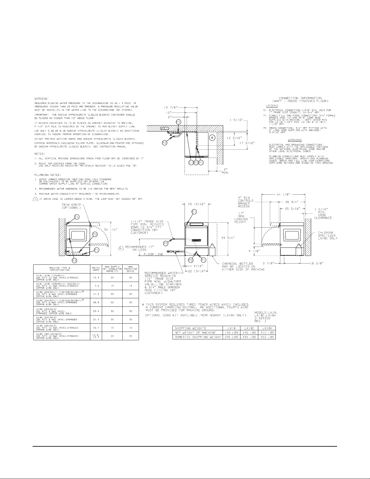
INSTALLATION DIAGRAM (LX18, LX18C & LX18H) — 329300
– 9 –
 Loading...