

LXi SERIES DISHWASHER
MODELS
LXiC ML-130016
LXiH ML-130017
LXi SERIES DISHWASHER
LXiGC ML-130018
LXiGH ML-130019
701 S. RIDGE AVENUE
TROY, OHIO 45374-0001
937 332-3000
www.hobartcorp.com
FORM 34779 Rev. C (August 2010)

© HOBART CORPORATION, 2010
– 2 –

TABLE OF CONTENTS
GENERAL .........................................................................................................................................4
INSTALLATION .................................................................................................................................5
Unpacking ...................................................................................................................................5
Location ......................................................................................................................................5
Leveling .......................................................................................................................................5
Water Requirements ...................................................................................................................5
Plumbing Connections ................................................................................................................ 6
Electrical Connection ..................................................................................................................7
Electrical Data ............................................................................................................................. 7
Detergent and Rinse Aid ............................................................................................................. 8
Operator Programming Mode .................................................................................................... 9
Chemical Sanitizer (LXiC and LXiGC) ........................................................................................ 12
OPERATION ....................................................................................................................................12
Before First Use ........................................................................................................................ 12
Controls ....................................................................................................................................12
Operating the LXi Dishwasher ...................................................................................................13
Diagnostic Messages ................................................................................................................ 14
Wash/Rinse Cycle Times (LXi) ................................................................................................... 14
Wash/Rinse Cycle Times (LXiG) ................................................................................................14
Preparation ..............................................................................................................................15
Do's and Don'ts For Your New Hobart Dishwasher .................................................................. 16
CLEANING ...................................................................................................................................... 17
Priming Chemical Pumps ..........................................................................................................18
MAINTENANCE ..............................................................................................................................19
Deliming ....................................................................................................................................19
Lubrication ................................................................................................................................19
TROUBLESHOOTING ..................................................................................................................... 20
– 3 –
Installation, Operation and Care of
LXi SERIES DISHWASHERS
SAVE THESE INSTRUCTIONS
GENERAL
The LXi Series dishwashers are fully automatic, front-loading dishwashing machines that are capable
of 30 racks per hour.
All LXi Series dishwashers shut down automatically 4 hours after last use to conserve energy.
All LXiH and LXiGH dishwashers include Sense-A-Temp™ to insure proper hot water temperature
during rinse.
Standard equipment includes two 20" x 20" racks, electronic controls, drain pump, ll hose and drain
hose.
MODEL DESCRIPTION
LXiC Fresh water rinse; low-temperature, chemical-sanitizing models for use
with 6% sodium hypochlorite solution (bleach) as the sanitizing agent.
Note: If 8.40% bleach is to be used, contact Hobart Service to change the
sanitizer pump settings. (Charges will apply)
LXiH Fresh water rinse with a built-in 70°F rise booster heater. This allows an
incoming water temperature of 110°F.
– 4 –

INSTALLATION
UNPACKING
Immediately after unpacking the dishwasher, check for possible shipping damage. If this machine is
found to be damaged, save packaging material and contact the carrier within 15 days of delivery.
LOCATION
Prior to installation, verify that the electrical supply agrees with the specications on the machine data
plate, which is located on the top of the door.
Steam generated from normal operation may escape from the door. Wood, laminates, veneers, etc. are
unsuitable materials for use in areas exposed to dishwasher steam and detergents. Stainless steel or
other moisture-resistant shields are recommended for surfaces adjacent to LXi sides and top.
LEVELING
The machine must be level to operate properly. Place the dishwasher in its operating location. Level
the machine before any connections are made. Using a carpenter's level placed diagonally on the rack
tracks, level the machine front to back and side to side by threading the adjustable feet in or out. After
leveling the machine, cover the exposed threads of the adjustable feet with black rubber tubing
supplied. (See separate instructions furnished with machine.)
WATER REQUIREMENTS
Proper water quality can improve warewashing performance by reducing spotting, lowering chemical
supply costs, enhancing effectiveness of labor and extending equipment life. Local water conditions
vary from one location to another. The recommended proper water treatment for effective and efcient
use of this equipment will also vary depending on the local water conditions. Ask your municipal water
supplier for details about local water specics prior to installation.
Recommended water hardness is 4 - 6 grains of hardness per gallon. Chlorides must not exceed 50
parts per million. Water hardness above 6 grains per gallon should be treated by a water conditioner
(water softener or in-line treatment). Water hardness below 4 grains per gallon also requires water
treatment to reduce potential corrosion. Water treatment has been shown to reduce costs associated
with machine cleaning, reduce deliming of the dishwasher, reduce detergent usage and reduce
corrosion of metallic surfaces in the booster water heater and dishwasher.
Sediment, silica, chlorides or other dissolved solids may lead to a recommendation for particulate
ltration or reverse osmosis treatment.
If an inspection of the dishwasher or booster heater reveals lime buildup after the equipment has been
in service, in-line treatment should be considered. If recommended, follow suppliers installation and
use instructions. Contact your local Hobart Service Ofce for specic recommendations.
– 5 –

Water Supply
A water hammer arrestor (meeting ASSE-1010 Standard or equivalent) should be installed (supplied
by others) in the common water supply line at the service connection.
Water must be proper hardness. Higher hardness may cause excessive formation of lime scale.
The plumber connecting this machine is responsible for making certain that water lines are
THOROUGHLY FLUSHED OUT BEFORE connecting to the dishwasher. This "ush-out" is necessary
to remove all foreign matter, such as chips (resulting from cutting or threading of pipes) pipe joint
compound from the lines; or, if soldered ttings are used, bits of solder or cuttings from the tubing.
Debris, if not removed, may lodge in the dishwasher's plumbing components and render them
inoperative. Manual valves or solenoid valves fouled by foreign matter and any expenses resulting from
this fouling, are NOT the responsibility of the manufacturer.
Water supply requirements are as follows:
MODEL TEMPERATURE FLOWING PRESSURE
LXiC 140°F Minimum 15 to 25 psi
LXiH 110°F Minimum 15 to 25 psi
If owing pressure exceeds 25 psi, a pressure reducing-valve (not supplied) must be installed in the
supply line.
CAUTION: The water pressure regulator must have a relief bypass. Failure to use the proper
type of pressure regulator may result in damage to the unit.
If owing pressure is less than 15 psi, improper machine operation may result.
A manual shutoff valve (not supplied) should be installed upstream of the ll hose to accommodate
servicing the machine.
It is recommended that a line strainer (not supplied) be installed in the supply line between the manual
shutoff valve (not supplied) and the connection point on the machine. Make plumbing connections with
1
⁄2" minimum copper piping OD (3⁄4" recommended), with a 3⁄4" male garden hose tting (not supplied).
See installation diagrams, pages 10-11.
NOTE: Iron in the water supply can cause staining. An iron lter is recommended for iron concentration
greater than 0.1 part per million. High chloride levels in the water supply can cause pitting. A chloride
removal system is required if levels exceed 50 parts per million.
PLUMBING CONNECTIONS
WARNING: PLUMBING CONNECTIONS MUST COMPLY WITH APPLICABLE SANITARY, SAFETY
AND PLUMBING CODES.
Drain
A drain hose, 3⁄4" diameter and 6' long, is provided. This should be securely plumbed into the sink
drain. Use care not to kink hose. See installation diagrams in this manual. Drain must have a minimum
ow capacity of 4 gallons per minute.
– 6 –
ledoM esahP/ztreH/stloV
tiucriCylppuSmuminiM
yticapmArotcudnoC
evitcetorPmumixaM
yticapmAeciveD
CiXL
CGiXL
1/06/021
02021/06/042-802
*1/06/)W3(042-802/021
HiXL
HGiXL
1/06/042/802
0505
*1/06/)W3(042-802/021
3/06/042-8025353
3/06/004-0835252
3/06/0840202
HiXL1/05/042-0220505
ELECTRICAL CONNECTION
WARNING: ELECTRICAL AND GROUNDING CONNECTIONS MUST COMPLY WITH THE
APPLICABLE PORTIONS OF THE NATIONAL ELECTRICAL CODE AND/OR OTHER LOCAL
ELECTRICAL CODES.
WARNING: DISCONNECT THE ELECTRICAL POWER TO THE MACHINE AND FOLLOW
LOCKOUT / TAGOUT PROCEDURES.
ELECTRICAL DATA
Complied in accordance with the National Electrical Code NFPA-70, latest addition.
NOTE: For supply connections, use copper wire only rated at 90°C minimum.
*The (3W) systems require three power wires that include a current carrying neutral. An additional
fourth wire must be provided for machine ground.
Refer to the data plate on the door handle of the machine and the label inside the control drawer at the
power connection for proper selection.
Use stranded copper wire suitable for at least 90°C.
– 7 –
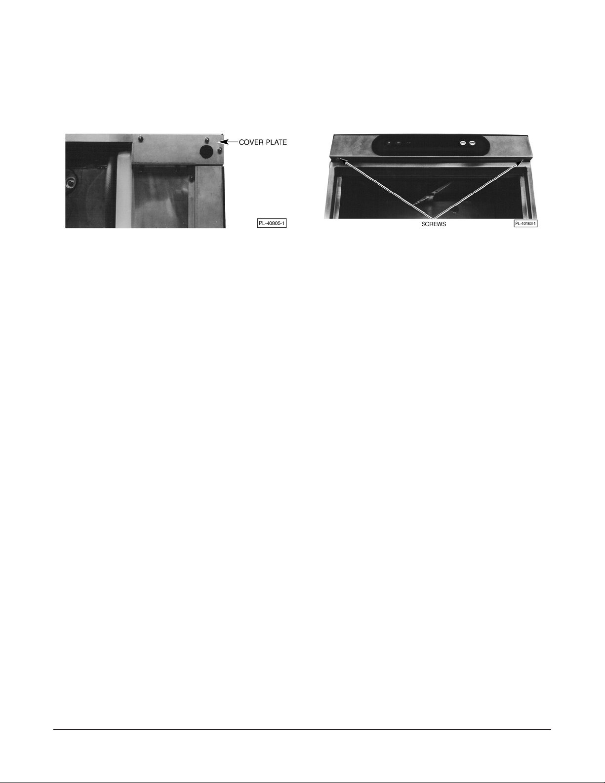
Connection Method
1. Remove the cover plate at the upper right in the back of the machine (Fig. 1). A hole for 1" trade
size conduit is supplied in the cover plate.
Fig. 1 Fig. 2
2. Remove the two screws (Fig. 2) securing the controls drawer and open it fully.
3. Install 1" trade conduit and tting to the cover plate. A 90 degree tting is recommended. Leave
at least four feet of electrical line between wall connection and cover plate connection. This
allows machine to be pulled away from the wall for cleaning.
4. Feed wires over top of tank to individual strain reliefs at rear of drawer. At least 32" and not more
than 36" of the required wire size must extend from the end of the conduit tting.
5. Reinstall the cover plate (three screws, Fig. 1).
6. For all wires, run one wire through each individual strain relief. (Four strain reliefs are provided.)
Make electrical connections according to wiring diagram supplied with the machine and secure
wires to the machine service connection. Keep excess wire in the drawer to a minimum.
7. Tighten the set screw on the strain relief(s) until they bottom out (on the shoulder of the body).
8. Close the control drawer and replace the screws.
DETERGENT AND RINSE AID
Use only commercial-grade detergents recommended by your chemical professional. Do not use
detergents formulated for residential dishwashers.
The detergent and rinse aid pump "ON" times are factory-set. If adjustments are required, contact
your local Hobart Service Ofce.
Place the detergent and rinse aid containers (which are obtained from an independent supplier) in a
location where the delivery tubes will reach them.
Remove the detergent bottle cap and put the red delivery tube in the detergent container.
Remove the rinse aid bottle cap and place the blue delivery tube in the rinse aid container.
Be sure to push the delivery tube standpipes completely to the bottom of each container. Check to make
sure there are no obstructions or kinks in the delivery tubes.
– 8 –

OPERATOR PROGRAMMING MODE
The Operator Programming mode allows changes to be made from factory settings to the chemical
pumps’ operation. This includes the Detergent and Rinse Aid pumps, but does not apply to the Sanitizer
pump on the LXiC and LXiGC models. The Detergent and/or Rinse Aid pumps can be turned off by
entering this programming mode. Disabling this feature will eliminate the alarm activation if no chemical
is sensed and turn the chemical pumps off. Machines not equipped with Hobart chemical pumps do not
have this programming mode.
1. To being the process start with the machine off.
2. First press the ON key, then immediately press and hold the OFF key to enter the user
programming mode. While the OFF key is being pressed the display will begin counting from "11"
going up to "99". Hold the OFF key until the counting ends and "WASH" and "Pr" is displayed on
the LED panel (Fig. 3). This indicates you are now in the programming mode. (The OFF key must
be pressed prior to the count reaching "44".)
Fig. 3
NOTE: If the "WASH" and "Pr" icons do not appear and the machine is equipped with the chemical
pumps, turn the unit off and try steps 1 through 3 again.
3. Press the WASH key to advance into the programming mode.
NOTE: The machine will shut off in 15 seconds if either the WASH key or the OFF key are not pressed.
To regain access to this mode follow steps 1 through 3.
4. The "DETERGENT" icon will now display either "On" or "OF" (Figs. 4 and 5). Pressing the WASH
key in either the Detergent or Rinse Aid mode changes the selection from "On" to "OF". When the
desired change is made press the OFF key to advance to the next mode.
Fig. 4 Fig. 5
NOTE: "On" indicates the Detergent or Rinse Aid pump will run and be sensed. "OF"" indicates the
Detergent or Rinse Aid pump is disabled, meaning it will not run or be sensed.
5. Pressing the OFF key advances to the Rinse Aid mode showing "On" or "OF". Press the WASH
key to change to desired setting.
6. When desired changes are completed allow the machine to turn itself off. It will do this
automatically after 15 seconds if no keys are depressed. The machine has saved changes and
is ready for use.
– 9 –

WARNING:
REQUIRED FLOWING WATER PRESSURE TO THE DISHMACHINE IS 20 ± 5 PSIG. IF
PRESSURES HIGHER THAN 25 PSIG ARE PRESENT, A PRESSURE REGULATING VALVE
MUST BE INSTALLED IN THE WATER LINE TO THE DISHMACHINE (BY OTHERS).
IMPORTANT: THE SODIUM HYPOCHLORITE (LIQUID BLEACH) CONTAINER SHOULD BE
PLACED NO HIGHER THAN 10" ABOVE FLOOR.
IF BLEACH CONTAINER IS TO BE PLACED IN CABINET ADJACENT TO MACHINE, A 1/2" DIA.
HOLE IS REQUIRED IN THE CABINET TO RUN BLEACH SUPPLY LINE.
USE ONLY 6% SODIUM HYPOCHLORITE (LIQUID BLEACH) AS SANITIZING CHEMICAL TO
INSURE PROPER OPERATION OF DISHMACHINE. IF 8.4% IS TO BE UTILIZED CONTACT
HOBART SERVICE TO CHANGE THE SANITIZER PUMP SETTINGS.
DO NOT PRE-MIX RINSE AGENT AND SODIUM HYPOCHLORITE (LIQUID BLEACH).
CERTAIN MATERIALS INCLUDING SILVER PLATE, ALUMINUM AND PEWTER ARE ATTACKED
BY SODIUM HYPOCHLORITE (LIQUID BLEACH). SEE INSTRUCTIONAL MANUAL.
STEAM GENERATED FROM NORMAL OPERATION MAY ESCAPE FROM THE DOOR. WOOD
LAMINATE, VENEERS, ETC. ARE UNSUITABLE MATERIALS FOR USE IN AREAS EXPOSED
TO DISHWASHER STEAM AND DETERGENTS. STAINLESS STEEL OR OTHER MOISTURERESISTANT SHIELDS ARE RECOMMENDED FOR SURFACES ADJACENT TO LXi SIDES
AND TOP.
NOTES:
1. ALL VERTICAL MACHINE DIMENSIONS TAKEN FROM FLOOR MAY BE INCREASED BY 1".
2. MOIST AIR ESCAPES FROM THE DOOR.
USE ONLY MOISTURE RESISTANT MATERIALS ADJACENT TO LXi SIDES AND TOP.
3. A VENT HOOD IS NOT RECOMMENDED ABOVE THE LXi UNDERCOUNTER DISHWASHER
SINCE IT DOES NOT PRODUCE EXCESSIVE VAPORS
PLUMBING NOTES:
1. WATER HAMMER ARRESTOR (MEETING ASSE-1010 STANDARD OR EQUIVALENT) TO BE
SUPPLIED (BY OTHERS) IN COMMON WATER SUPPLY LINE AT SERVICE CONNECTION.
2. RECOMMENDED WATER HARDNESS TO BE 4-6 GRAINS FOR BEST RESULTS.
3. MINIMUM WATER CONDUCTIVITY REQUIRED - 30 MICRO-MHOS/CM.
4. IF DRAIN HOSE IS LOOPED ABOVE A SINK, THE LOOP MUST NOT EXCEED 38" AFF.
CONNECTION INFORMATION
(AFF = ABOVE FINISHED FLOOR)
LEGEND
E1 ELECTRICAL CONNECTION: 1-3/8" DIA. HOLE
FOR 1" TRADE SIZE CONDUIT; 31-3/4" AFF.
P1 SINGLE FILL AND RINSE CONNECTION:
3/4" FEMALE GARDEN HOSE FITTING ON 6' LONG
HOSE SUPPLIED WITH MACHINE; 140°F WATER
MIN. FOR LXiC, 110°F WATER MIN. FOR LXiH,
1-1/2" AFF.
P2 DRAIN CONNECTION: 3/4" MPT FITTING WITH
6' LONG HOSE SUPPLIED WITH MACHINE;
3-9/16" AFF.
MACHINE TYPE &
SPECIFICATION
LXiC (120/60/1)
USE 90°C STRANDED 15.4 20 20
COPPER WIRE ONLY.
LXiC (120/208-240(3W)/60/1*)
LXiC (208-240/60/1)
USE 90°C STRANDED 13.6 20 20
COPPER WIRE ONLY.
LXiH (120/208-240(3W)/60/1*)
LXiH (208-240/60/1)
USE 90°C STRANDED
COPPER WIRE ONLY. 37.7 50 50
ELECTRICAL OPTIONS BELOW ARE NON STANDARD VOLTAGES AVAILABLE
AT EXTRA COST. CONSULT FACTORY FOR PRICING AND LEAD TIME.
LXiH 208-240/60/3 29.5 35 35
480/60/3 14.8 20 20
220-240/50/1 38.1 50 50
380-400/60/3 17.1 25 25
RATED
MIN SUPPLY MAX
AMPS
CKT CONDUCT PROTECTIVE
AMPACITY DEVICES
INSTALLATION DIAGRAM (LXiC & LXiH)
– 10 –
* THIS SYSTEM REQUIRES THREE POWER WIRES WHICH INCLUDES
A CURRENT CARRYING NEUTRAL, AN ADDITIONAL FOURTH WIRE
MUST BE PROVIDED FOR MACHINE GROUND.
ACCESSORY CORD KITS AVAILABLE FOR ALL MACHINES
SHIPPING WEIGHTS (LBS) LXiC LXiH
NET WEIGHT OF MACHINE 190 lbs. 210 lbs.
DOMESTIC SHIPPING WEIGHT 235 lbs. 255 lbs.
WARNING
ELECTRICAL AND GROUNDING CONNECTIONS
MUST COMPLY WITH THE APPLICABLE PORTIONS
OF THE NATIONAL ELECTRICAL CODE AND/OR
OTHER LOCAL ELECTRICAL CODES.
PLUMBING CONNECTIONS MUST COMPLY WITH
APPLICABLE SANITARY, SAFETY AND PLUMBING
CODES. DRAIN AND FILL LINE CONFIGURATIONS
VARY, SOME METHODS ARE SHOWN ON THIS DRAWING.

WARNING:
REQUIRED FLOWING WATER PRESSURE TO THE GLASSWASHER IS 20 ± 5 PSIG. IF
PRESSURES HIGHER THAN 25 PSIG ARE PRESENT, A PRESSURE REGULATING VALVE
MUST BE INSTALLED IN THE WATER LINE TO THE GLASSWASHER (BY OTHERS).
IMPORTANT: THE SODIUM HYPOCHLORITE (LIQUID BLEACH) CONTAINER SHOULD BE
PLACED NO HIGHER THAN 10" ABOVE FLOOR.
IF BLEACH CONTAINER IS TO BE PLACED IN CABINET ADJACENT TO GLASSWASHER, A
1/2" DIA. HOLE IS REQUIRED IN THE CABINET TO RUN BLEACH SUPPLY LINE.
USE ONLY 6% SODIUM HYPOCHLORITE (LIQUID BLEACH) AS SANITIZING CHEMICAL TO
INSURE PROPER OPERATION OF DISHMACHINE. IF 8.4% IS TO BE UTILIZED CONTACT
HOBART SERVICE TO CHANGE THE SANITIZER PUMP SETTINGS.
DO NOT PRE-MIX WETTING AGENT AND SODIUM HYPOCHLORITE (LIQUID BLEACH).
CERTAIN MATERIALS INCLUDING SILVER PLATE, ALUMINUM AND PEWTER ARE ATTACKED
BY SODIUM HYPOCHLORITE (LIQUID BLEACH). SEE INSTRUCTIONAL MANUAL.
NOTES:
1. ALL VERTICAL MACHINE DIMENSIONS TAKEN FROM FLOOR MAY BE INCREASED BY 1".
2. MOIST AIR ESCAPES FROM THE DOOR.
USE ONLY MOISTURE RESISTANT MATERIALS ADJACENT TO LXiG SIDES AND TOP.
3. A VENT HOOD IS NOT RECOMMENDED ABOVE THE LXiG U N DE RC OU N TER
GLASSWASHER SINCE IT DOES NOT PRODUCE EXCESSIVE VAPORS
PLUMBING NOTES:
1. WATER HAMMER ARRESTOR (MEETING ASSE-1010 STANDARD OR EQUIVALENT) TO BE
SUPPLIED (BY OTHERS) IN COMMON WATER SUPPLY LINE AT SERVICE CONNECTION.
2. RECOMMENDED WATER HARDNESS TO BE 4-6 GRAINS FOR BEST RESULTS.
3. MINIMUM WATER CONDUCTIVITY REQUIRED - 30 MICRO-MHOS/CM.
4. IF DRAIN HOSE IS LOOPED ABOVE A SINK, THE LOOP MUST NOT EXCEED 38" AFF.
CONNECTION INFORMATION
(AFF = ABOVE FINISHED FLOOR)
LEGEND
E1 ELECTRICAL CONNECTION: 1-3/8" DIA. HOLE
FOR 1" TRADE SIZE CONDUIT; 31-3/4" AFF.
P1 SINGLE FILL AND RINSE CONNECTION:
3/4" FEMALE GARDEN HOSE FITTING ON 6' LONG
HOSE SUPPLIED WITH MACHINE; 140°F WATER
MIN. FOR LXiGC, 110°F WATER MIN. FOR LXiGH,
1-1/2" AFF.
P2 DRAIN CONNECTION: 3/4" MPT FITTING WITH
6' LONG HOSE SUPPLIED WITH MACHINE;
3-9/16" AFF.
MACHINE TYPE & RATED
SPECIFICATION
LXiGC (120/60/1)
USE 90°C STRANDED 15.4 20 20
COPPER WIRE ONLY.
LXiGC (120/208-240(3W)/60/1*)
LXiGC (208-240/60/1)
USE 90°C STRANDED 13.6 20 20
COPPER WIRE ONLY.
LXiGH (120/208-240(3W)/60/1*)
LXiGH (208-240/60/1)
USE 90°C STRANDED
COPPER WIRE ONLY. 37.7 50 50
ELECTRICAL OPTIONS BELOW ARE NON STANDARD VOLTAGES AVAILABLE
AT EXTRA COST. CONSULT FACTORY FOR PRICING AND LEAD TIME.
LXiGH 208-240/60/3 29.5 35 35
480/60/3 14.8 20 20
220-240/50/1 38.1 50 50
380-400/60/3 17.1 25 25
MIN SUPPLY MAX
AMPS
CKT CONDUCT PROTECTIVE
AMPACITY DEVICES
INSTALLATION DIAGRAM (LXiGC & LXiGH)
– 11 –
* THIS SYSTEM REQUIRES THREE POWER WIRES WHICH INCLUDES
A CURRENT CARRYING NEUTRAL, AN ADDITIONAL FOURTH WIRE
MUST BE PROVIDED FOR MACHINE GROUND.
ACCESSORY CORD KITS AVAILABLE FOR ALL MACHINES
SHIPPING WEIGHTS (LBS) LXiGC LXiGH
NET WEIGHT OF MACHINE 194 lbs. 214 lbs.
DOMESTIC SHIPPING WEIGHT 239 lbs. 259 lbs.
WARNING
ELECTRICAL AND GROUNDING CONNECTIONS
MUST COMPLY WITH THE APPLICABLE PORTIONS
OF THE NATIONAL ELECTRICAL CODE AND/OR
OTHER LOCAL ELECTRICAL CODES.
PLUMBING CONNECTIONS MUST COMPLY WITH
APPLICABLE SANITARY, SAFETY AND PLUMBING
CODES. DRAIN AND FILL LINE CONFIGURATIONS
VARY, SOME METHODS ARE SHOWN ON THIS DRAWING.

CHEMICAL SANITIZER (LXiC AND LXiGC)
CAUTION: Items such as pewter, aluminum and silver will be attacked by sodium hypochlorite
(bleach). Therefore, chemical-sanitizing dishwashers should not be used to wash such items.
On model LXiC only, the chemical sanitizer pump is factory-set for use with 6% sodium hypochlorite
solution. If 8.40% sodium hypochlorite solution is to be used, contact your local Hobart Service
Office.
Place a 1-gallon bottle of 6% or 8.40% sodium hypochlorite solution (bleach) in a suitable location no
higher than 10 inches off the oor. Do not pre-mix sanitizing solution with water or any other liquid.
WARNING: NEVER PREMIX A WETTING AGENT WITH THE SANITIZING SOLUTION. MIXING
MAY CAUSE HAZARDOUS GAS TO FORM.
Remove the sanitizer bottle cap and place the white delivery tube in the sanitizer container. Be sure
to push the delivery tube standpipe completely to the bottom of the container. Check to make sure
there are no obstructions or kinks in the delivery tube.
The LXi Series Dishwasher has an auto-prime cycle. (See Operating the LXi Dishwasher.)
Frequently check your sanitizer bottle to make sure there is a sufcient chemical supply.
OPERATION
CAUTION: Items such as pewter, aluminum and silver will be attacked by sodium hypochlorite
(bleach). Therefore, chemical-sanitizing dishwashers should not be used to wash such items.
If your dishwasher is a chemical-sanitizing model, frequently check the sanitizer bottle to make sure
there is a sufcient chemical supply.
BEFORE FIRST USE
This machine must be cleaned after installation and before being put into operation. (See Cleaning.)
CONTROLS
Fig. 6
– 12 –

OPERATING THE LXi DISHWASHER
SIHTOD SWOHSYALPSID SKRAMER
.NOsserP
.rebmunledoM
sihT.kcehc-flessmrofreprehsawhsiD
.sdnoces01-5sekat
erutarepmetpmusdnatilLLIF
sienihcamnehwdeyalpsid
.gnillif
lliF sehsalf siretsoobnehw
.HiXLledomnognitaeherp
otpuekatdluoctaeherpsihT
.setunim8
,dellifnehW.retawhtiwsllifrehsawhsiD
.sdnoces01rofnosnrutpmup
lliwllif,elcycllifgniruddeneposiroodfI
ssecorpeht,desolcsiroodretfA.pots
.deppotstierehwseunitnoc
a,elcycllifagniruddesserpsiHSAWfI
.
elcyclliffodnetanigeblliwelcychsaw
,lliftonlliwenihcamdnasdnuosrepeebfI
yrtdna,noneht,fforekaerbtiucricnrut
ruoytcatnoc,stsisrepmelborpfI.niaga
.eciffOecivreStraboHlacol
erutarepmetpmus,llifgniruD
.deyalpsidsi
naniatniamlliwenihcam,dellifnehW
htobnideniatniamsitaeH.etatseldi
.pmusro/dnaretsoob
sehsidfokcaredils;roodnepO
ddadnarehsawhsidotni
.roodesolC.tnegreted
.erutarepmetpmuShtiwdeppiuqesiseireSiXLledoMruoyfI
tnegreted,pmuptnegretedlanoitpoeht
hsawgnirudyllacitamotuadeddaeblliw
.elcyc
.HSAWsserPerutarepmetpmus;tilHSAW
.elcychsawgniruddeyalpsid
erutarepmetesnir;tilESNIR
.elcycesnirgniruddeyalpsid
.elcycesnirdnahsawasetaitinienihcaM
elcyc,elcychsawgniruddeneposiroodfI
siroodnehwgninnigebmorftratserlliw
.desolc
niardroesnirgniruddeneposiroodfI
erehwtnioptaeunitnoclliwelcyc,elcyc
.roodgnisolcnopudeneposawrood
enihcam,elc
ycgniruddesserpsiFFOfI
.nwodtuhsdnaniardlliw
daoler,etelpmocsielcycnehW
;elcycesnir/hsawtxenrofenihcam
lliwenihcam,esunitonfi,ro
.edomeldiniatniam
.erutarepmetpmuSehtfinwodtuhsdnaniardlliwenihcaM
siemitnwodtuhseldidemmargorp
.dehcaer
.FFOsserp,yadfodneehttA
ehtnitneserpsiretawfI
nehtdeyalpsidsi"dP",pmus
.nwodstuhsyalpsideht
lliwenihcam,desserpsiyekFFOnehW
.nwodtuhsdnaniard
– 13 –

DIAGNOSTIC MESSAGES
In the event of a problem with a temperature probe, the display will ash P1, P2 or P3 every second.
The respective heaters will shut down. Other functions will continue to operate normally. Contact your
local Hobart Service Ofce.
Drain and ll error messages are displayed as E0, E1, E2, E3, E4, E5, E6 or E7. In all cases, the
dishwasher will terminate current cycle operations, turn off all heat sources and display the message
until the OFF button is pressed. (A power drain will not occur when turned off.) (See Troubleshooting.)
If problem persists, contact your local Hobart Service Ofce.
If the control detects that the water level probe is becoming less sensitive, CL and Pr are displayed in
the control window. Clean all three water level probes. (See Cleaning.)
WASH/RINSE CYCLE TIMES (LXi)
Spritz 2 Sec.
Wash 82 Sec.**
Drain 22 Sec. Max.*
Dwell 1 Sec.
Rinse 10 Sec.
Dwell 5 Sec.
* Drains off about 3⁄4 gallon of water.
** Maximum wash time may vary, depending on operation voltage and incoming water temperature
for 70°F rise.
WASH/RINSE CYCLE TIMES (LXiG)
Spritz 2 Sec.
Wash 59 Sec.**
Drain 22 Sec. Max.*
Dwell 1 Sec.
Rinse 10 Sec.
Dwell 5 Sec.
* Drains off about 3⁄4 gallon of water.
** Maximum wash time may vary, depending on operation voltage and incoming water temperature
for 70°F rise.
– 14 –

PREPARATION
COARSE STRAINER
FINE STRAINER
Make sure the coarse (Fig. 7) and ne (Fig. 8) strainers are in place and free of debris. Check both wash
arms and rinse arms to make sure they spin freely and are not clogged.
Fig. 7 Fig. 8
Dishes must be scraped and/or rinsed to remove food particles and other debris. Never use steel wool
on ware to be loaded into the dishwasher. Place dishes in a rack. Do not stack dishes on top of each
other as water must have free access to all sides of every dish. Stand plates edgewise in a peg-type
rack (Fig. 9). Cups, glasses and bowls should lay upside down in an open or compartment-type rack
(Fig. 9). Silverware and other small pieces should lay loosely on the bottom of a at-bottom rack. See
Operator Card (supplied) for other loading patterns. Do not allow foreign objects to enter the unit,
especially metallic contaminants such as staples and paper clips.
Check to see if any detergent, rinse aid or sanitizer chemicals need to be replenished. Use only
commercial-type detergents, as prescribed by your chemical professional.
Fig. 9
– 15 –

DO'S AND DON'TS FOR YOUR NEW HOBART DISHWASHER
DO assure proper water hardness.
DO prescrape dishes thoroughly.
DO use only detergents recommended by your chemical professional.
DO, at the end of the day, thoroughly cleanse the machine, rinse and dry. (Leave door open.)
DO closely follow your chemical professional's prescribed deliming schedule.
DO use only products formulated to be safe on stainless steel.
DO NOT oversoften water. (Recommended water hardness is no less than 4 grains per gallon.)
DO NOT use detergents formulated for residential dishwashers.
DO NOT allow food soil to accumulate on the tank bottom.
DO NOT exceed chemical manufacturer's recommended concentrations for detergent, sanitizer, rinse
aid or lime scale remover.
DO NOT use steel wool to clean ware or warewasher surface.
DO NOT allow foreign objects to enter the unit, especially metallic contaminants.
NOTE: Failure to follow use, care and maintenance instructions may void your Hobart warewasher
warranty.
– 16 –

CLEANING
THUMB NUT
WATER LEVEL PROBE
This machine must be cleaned at least once each working day. Use only products formulated to be safe
on stainless steel.
1. Press OFF. The machine will drain. When the
display is no longer lit, open the door and remove
any debris from the bottom of the tank. Do not
allow food soil to accumulate on the tank bottom.
2. Remove the lower rinse arm by unscrewing the
thumb nut (Fig. 10). Remove the lower wash arm
by pulling the arm off the shaft. Remove the upper
rinse and wash arms in the same manner. Remove
the coarse and ne strainers. (See Figs. 7 and 8).
Thoroughly clean these items in a sink. Remove
debris from wash/rinse arm nozzles.
Fig. 10
3. With a damp cloth, wipe the interior of the machine. With a nonmetallic scouring pad, clean the
rear water level probes (Fig. 11) and the front water level probe (Fig. 12) under the ne strainer.
DO NOT use steel wool. Wipe the exterior of the machine. When cleaning the inside of the door,
be sure to wipe the lip at the bottom of the door. Remove any remaining debris with a mild cleanser
formulated for stainless steel and a soft cloth or brush.
Fig. 11 Fig. 12
4. Replace the coarse and ne strainers. Reinstall the lower wash arm by pushing it down on the
shaft and then place the lower rinse arm on the shaft and securely tighten the thumb nut. Spin
arms to make sure they spin freely. Repeat this procedure with the upper wash and rinse arms.
5. Use a soft, damp cloth or sponge and mild cleanser to clean the control keypad and display. DO
NOT use abrasive or harsh cleaners or scouring pads.
6. Leave the door ajar overnight to allow the interior to air out and dry.
– 17 –

PRIMING CHEMICAL PUMPS
When a chemical becomes empty, the priming operation starts automatically the next time the machine
is turned on or a wash cycle is started. This feature is only supported on machines with the chemical
sense board installed and where CHEMICAL SENSING is enabled. Note that the initial prime time for
all pumps (Detergent, Rinse Agent and Sanitizer) is 60 seconds during which time the chemical icon
will ash. If the chemical is not sensed within 60 seconds, the chemical icon will remain lit and the control
will beep for about 5 seconds. After the chemical is sensed, the indicator in the display turns off; and
the pump continues to prime for 20 seconds to allow the chemicals to reach the machine. If all
chemicals are empty, the sanitizer will prime rst followed by detergent. Only one chemical pump will
run at a time.
If chemicals are not sensed after three consecutive priming operations, the wrench is displayed along
with the empty chemical icon and priming is cancelled. The next time a wash cycle is started, the control
will ash the wrench and empty chemical icon as well as beep. This is to prevent the priming operation
in case the chemical sensors have malfunctioned. Verify that the chemical bottles are not empty. If they
are not empty, the chemical sensor or pumps have malfunctioned; contact your local Hobart Service
Ofce.
The priming operation can be reset by either:
• PressingtheWASHkeyasecondtimewhilethewrenchandemptychemicaliconisashing.
• Byturningthedishwasheroff,thenbackon.
NOTE: If the use of chemical pumps is not desired, refer to the Operator Programming Mode section.
– 18 –

MAINTENANCE
DELIMING
WARNING: DELIMING SOLUTION, RINSE AGENTS OR ANY OTHER KIND OF ACID MUST NOT
COME IN CONTACT WITH BLEACH OR RINSE SOLUTION CONTAINING BLEACH USED IN
CHEMICAL-SANITIZING MACHINES. MIXING MAY CAUSE HAZARDOUS GAS TO FORM. THIS
ENTIRE PROCEDURE MUST BE FOLLOWED STEP BY STEP FOR SAFE AND SATISFACTORY
RESULTS.
CAUTION: Do not allow the deliming agent to remain in the machine longer than recommended
by the deliming agent manufacturer.
DELIME THE DISHWASHER ON A REGULAR BASIS AS REQUIRED. The regularity will depend on
mineral content of the supply water. Deliming should be done when you can see clear signs of lime
deposits (a white, chalky substance) on the inside walls and on the wash arms. LXi models are
equipped with an automatic delime cycle reminder. It is recommended that deliming be done when
DELIME ashes.
If deliming is necessary, a deliming agent (such as Lime Away or LSR) should be used for best results.
After the preprogrammed number of cycles has expired, which is factory-set for 1500 cycles, the
control will indicate the delime request by displaying DELIME. Machine operation will continue as usual.
To remove the DELIME icon, you must either enter a delime cycle or reprogram the number of cycles
to terminate the DELIME indication. (If the dishwasher needs to be reprogrammed, contact your local
Hobart authorized service ofce.)
1. Remove rack from machine. Close door.
2. Press OFF to power down the dishwasher.
3. Press and hold WASH (DELIME) while pressing ON. The display will show DELIME during the
ll cycle.
4. After the ll cycle, the control will prompt you to add delimer by ashing ADD and DELIME. Open
the door and add deliming agent. (Carefully follow supplier's instructions.) The sump holds
approximately 3 gallons of water.
5. After delimer has been added, close the door. Press the WASH (DELIME) key again to continue
the cycle. The machine will enter the wash mode for 5 minutes, then will begin two rinse and drain
operations. The DELIME symbol will ash in the display.
NOTE: DO NOT interrupt the cycle. Should the process be interrupted, restart delime procedure from
the beginning.
6. After the deliming operation is completed, power to the control will be turned off.
7. Inspect the interior of the machine for lime deposits. If necessary, repeat steps 3 through 7.
LUBRICATION
The pump motor has permanently sealed bearings and requires no lubrication.
– 19 –

TROUBLESHOOTING
This section outlines various symptoms and possible causes that may be encountered in the event of
abnormal machine operation. If symptoms persist after possible causes have been checked, service
may be required.
Symptom Possible Causes
No machine operation
(no display).
No machine operation
(with display).
Dishes not clean. 1. Strainers clogged causing inadequate water supply to pump -
Spotting of silverware,
glasses or dishes.
1. Machine OFF - turn machine ON.
2. Blown fuse or circuit breaker off at power supply.
3. Cord not plugged in (corded models only)
1. Display: "dr" "oP" - open and close door. If problem persists,
contact your local Hobart Service Ofce.
2. See "Machine won't ll or won't ll high enough."
clean according to instructions. (See Cleaning.)
2. Obstruction in wash arm(s) or wash arms will not turn - clean
3. Wash or rinse arms will not turn - check that they spin.
4. Detergent dispenser may be clogged.
5. Soil quantity - scrape dishes before cycle.
6. Improper rack loading - see Preparation in this manual.
7. Low water - check water pressure.
8. Water temperature too low - note wash temperature on display
during WASH; should be above 120°F for chemical-sanitizing
machines and above 150°F for other machines.
9. Incoming water supply turned off.
1. Improperly loaded racks.
2. Water temperature too low.
3. Improper type or concentration of detergent - contact your
local detergent representative.
4. Hard water - install a water softener; use a rinse agent.
5. Insufcient ll - check water pressure.
Chemicals not feeding. 1. Low on chemicals - check levels.
2. Air leak at feeder hose connections - check for snugness.
3. Tubes kinked - check for smooth bends.
Food soils remain in
dishwasher.
Follow daily cleaning instructions. (See Cleaning.)
– 20 –

Symptom Possible Causes
Unexpected results on
dishes.
Low-temperature readings. 1. Low water supply temperature - make sure it meets the
1. Etching - usually caused by any combination of high
temperatures, soft water, soft glass or high alkaline washing
solutions.
2. Tarnishing - avoid washing silver, silver plates and pewter in
chemical-sanitizing machines.
3. Pitting - stainless steel may pit with lengthy contact of foods
containing salt, fruit juices, vinegar, etc. Wash immediately.
4. Black or gray marks - may have been rubbed with aluminum.
5. Brown stains - may be due to high iron content in water supply.
6. Chipping - improper loading or ware is too delicate.
7. Fading of china patterns - usually due to high water temperature
and strong detergent. Check that china is dishwasher compatible.
8. Wooden ware damage - avoid washing in dishwasher.
9. Rust on cast iron - seasoning is lost in dishwasher. Avoid
dishwasher cleaning.
10. Plastic ware distortion - high temperatures. Check plastic
ware's instructions.
recommended limits.
2. Rapid cycle use - if incoming water temperature is low and
cycle use rate is high, the hot water supply may be insufcient
to meet the demand.
3. Heavy ware load cools wash water - do not overload racks.
4. Booster heater or sump heater set low - contact your local
Hobart Service Ofce.
Machine will not ll or will not
ll high enough.
(Display shows E0, E2,
E3 or E4. Machine will not
run).
1. Low water pressure - check for clogged hose strainer; ensure
the site water pressure meets minimum ow pressures.
2. Make sure probes are clean. (See Cleaning.)
3. No water pressure - main water supply valves may not be
working.
4. Anti-siphon valve - located in the lower left area of the chamber
just above the water line. Drain the machine and insert toothpick
or similar object into hole to verify ball (3⁄16 " OD) is free to oat.
5. Delime machine.
– 21 –

Symptom Possible Causes
Machine lls too high or
leaks from door.
(Display shows CL/Pr.)
Machine will not drain.
(Display shows E5).
Some water occasionally
drips out of rinse arms
(H dishwashers only).
Machine displays E6. Contact your local Hobart Service Ofce.
Machine lights up wrench
and ashes P1, P2 or P3.
Machine lights up wrench
and chemical icon.
1. Machine not level - see LEVELING in this manual.
2. Fill solenoid valve leaking - turn the dishwasher OFF; if water
continues to come in, contact your local Hobart Service Ofce.
3. Clean water level probes. (See Cleaning.)
1. Drain pipes restricted - check dishwasher drain line for kinks;
ensure proper drain rate is allowed from plumbing.
2. Turn machine OFF. Wait several seconds and then turn back
ON. Repeat this procedure twice if necessary. If problem
persists, contact your local Hobart Service Ofce.
This is normal due to expansion of water being heated in the
booster tank.
Contact your local Hobart Service Ofce.
Refer to Priming Chemical Pumps.
– 22 –

NOTES
– 23 –

NOTES
FORM 34779 Rev. C (August 2010) PRINTED in U.S.A.
– 24 –
 Loading...