


 Loading...
GE Digital Energy
Multilin
MX350
Automatic Transfer Control
System
Low voltage power transfer control
Instruction manual
MX350 revision: 1.2x
Manual P/N: 1601-9071-A2
GE publication code: GEK-113497A
Copyright © 2010 GE Multilin
GE Digital Energy
Power Quality / Zenith
830 W. 40th Street
Chicago IL, 60609
USA
Tel: 800-637-1738
email: GEPQSales@ge.com
Internet: http://www.gedigitalenergy.com/ats
*1601-9071-A2*
|
|
ISTE |
R |
||
|
G |
||||
R |
E |
|
|
E |
|
|
|
|
D |
||
|
|
|
|
|
|
ISO9001:2000 |
|||||
E |
|
|
|
IN |
|
G |
|
|
L |
||
|
|
|
I |
|
|
|
|
MULT |
|
|
|
GE Multilin's Quality Management System is registered to ISO9001:2000
QMI # 005094
© 2010 GE Multilin Incorporated. All rights reserved.
GE Multilin MX350 Automatic Transfer Control System instruction manual for revision 1.2x.
MX350 Automatic Transfer Control System, EnerVista, EnerVista Launchpad, EnerVista MX350 Setup, and FlexLogic are registered trademarks of GE Multilin Inc.
The contents of this manual are the property of GE Multilin Inc. This documentation is furnished on license and may not be reproduced in whole or in part without the permission of GE Multilin. The content of this manual is for informational use only and is subject to change without notice.
Part number: 1601-9071-A2 (April 2010)

Table of Contents
1. INTRODUCTION |
Overview ............................................................................................................ |
1 - 1 |
|
Cautions and warnings............................................................................................................... |
1 - 1 |
|
Description of the Automatic Transfer Controller system.......................................... |
1 - 2 |
|
ATS types ........................................................................................................................................... |
1 - 5 |
|
Specifications .................................................................................................... |
1 - 6 |
|
Timing specifications ................................................................................................................... |
1 - 6 |
|
Protection specifications............................................................................................................ |
1 - 6 |
|
User interface specifications.................................................................................................... |
1 - 7 |
|
Metering and monitoring specifications............................................................................. |
1 - 7 |
|
Inputs specifications .................................................................................................................... |
1 - 7 |
|
Outputs specifications ................................................................................................................ |
1 - 8 |
|
Power supply specifications..................................................................................................... |
1 - 8 |
|
Communications specifications ............................................................................................. |
1 - 9 |
|
Testing and certification............................................................................................................. |
1 - 9 |
|
Physical specifications .............................................................................................................. |
1 - 10 |
|
Environmental specifications................................................................................................. |
1 - 10 |
|
Order codes for MX350 ................................................................................. |
1 - 11 |
|
Example of an MX350 order code ....................................................................................... |
1 - 11 |
|
|
|
2. INSTALLATION |
Mechanical installation ................................................................................... |
2 - 1 |
|
Dimensions....................................................................................................................................... |
2 - 1 |
|
Product identification .................................................................................................................. |
2 - 2 |
|
Mounting ........................................................................................................................................... |
2 - 2 |
|
Module withdrawal and insertion.......................................................................................... |
2 - 4 |
|
Module and terminal identification....................................................................................... |
2 - 6 |
|
Electrical installation ....................................................................................... |
2 - 7 |
|
Power supply module.................................................................................................................. |
2 - 8 |
|
CPU module...................................................................................................................................... |
2 - 9 |
|
Input/Output modules............................................................................................................... |
2 - 10 |
|
Dielectric strength testing ....................................................................................................... |
2 - 14 |
3. INTERFACING WITH THE MX350 AT CONTROLLER
Graphical control panel................................................................................... |
3 - 1 |
Introduction to the graphical control panel...................................................................... |
3 - 1 |
MX350 graphical display pages.............................................................................................. |
3 - 6 |
MX350 programming techniques........................................................................................ |
3 - 13 |
EnerVista™ MX350 Setup Software............................................................ |
3 - 17 |
Software requirements............................................................................................................. |
3 - 17 |
Troubleshooting the USB driver............................................................................................ |
3 - 17 |
Installing the EnerVista™ MX350 Setup software........................................................ |
3 - 20 |
Connecting EnerVista MX350 Setup to the relay ......................................................... |
3 - 20 |
Working with setpoints and setpoint files........................................................................ |
3 - 23 |
Upgrading relay firmware ....................................................................................................... |
3 - 29 |
Power analysis ............................................................................................... |
3 - 30 |
Waveform capture...................................................................................................................... |
3 - 30 |
Data logger..................................................................................................................................... |
3 - 34 |
4. ACTUAL VALUES |
Actual values overview |
....................................................................................4 - 1 |
MX350 AUTOMATIC TRANSFER CONTROL SYSTEM – INSTRUCTION MANUAL |
toc–i |

|
Metering ............................................................................................................ |
4 - 2 |
|
Current metering............................................................................................................................ |
4 - 2 |
|
Voltage metering............................................................................................................................ |
4 - 2 |
|
Power metering .............................................................................................................................. |
4 - 3 |
|
PQ metering...................................................................................................................................... |
4 - 3 |
|
Status................................................................................................................. |
4 - 4 |
|
Status messages ............................................................................................................................ |
4 - 4 |
|
Input and output status .............................................................................................................. |
4 - 4 |
|
System Page..................................................................................................................................... |
4 - 5 |
|
Flex Page............................................................................................................................................ |
4 - 5 |
|
|
|
5. SETPOINTS |
Understanding setpoints................................................................................ |
5 - 1 |
|
Setpoint text abbreviations ....................................................................................................... |
5 - 2 |
|
Configuration setpoints ................................................................................. |
5 - 3 |
|
ATS setpoints.................................................................................................................................... |
5 - 3 |
|
ATS types............................................................................................................................................ |
5 - 4 |
|
Chicago Transfer Alarm Panel (CTAP) option .................................................................... |
5 - 7 |
|
Common ATS setpoints ............................................................................................................... |
5 - 8 |
|
Current and voltage transformers......................................................................................... |
5 - 9 |
|
Inputs................................................................................................................................................ |
5 - 10 |
|
Outputs ............................................................................................................................................ |
5 - 10 |
|
Communications setpoints..................................................................................................... |
5 - 10 |
|
System.............................................................................................................................................. |
5 - 12 |
|
Events ............................................................................................................................................... |
5 - 13 |
|
Zenith................................................................................................................................................ |
5 - 13 |
|
Operation setpoints ...................................................................................... |
5 - 14 |
|
Timers ............................................................................................................................................... |
5 - 15 |
|
Control ............................................................................................................. |
5 - 16 |
|
General............................................................................................................................................. |
5 - 16 |
|
Interlock........................................................................................................................................... |
5 - 18 |
|
Alarms .............................................................................................................................................. |
5 - 19 |
|
Security............................................................................................................ |
5 - 20 |
|
|
|
6. EXERCISER |
Information....................................................................................................... |
6 - 1 |
|
Setup .................................................................................................................................................... |
6 - 2 |
|
Test........................................................................................................................................................ |
6 - 2 |
|
|
|
7. DIAGNOSTICS |
Events ................................................................................................................ |
7 - 1 |
|
Statistical information.................................................................................... |
7 - 3 |
|
Phasors.............................................................................................................. |
7 - 4 |
|
Product information........................................................................................ |
7 - 5 |
|
Reports .............................................................................................................. |
7 - 6 |
|
Waveform ......................................................................................................... |
7 - 7 |
|
Datalog .............................................................................................................. |
7 - 8 |
|
|
|
8. FLEXLOGIC™ |
FlexLogic™ overview....................................................................................... |
8 - 1 |
|
Introduction to FlexLogic™........................................................................................................ |
8 - 1 |
|
|
|
9. COMMUNICATIONS |
Communications interfaces .......................................................................... |
9 - 1 |
toc–ii |
MX350 AUTOMATIC TRANSFER CONTROL SYSTEM – INSTRUCTION MANUAL |

Digital Energy
Multilin
MX350 Automatic Transfer Control
System
Chapter 1: Introduction
Overview
The MX350 is a modular control and monitoring system designed specifically for lowvoltage transfer switch application. The MX350 provides the following key benefits.
•Flexible control and communication options to suit any low-voltage transfer switch application.
•Small footprint.
•Modular design reduces the number of spare components for maintenance and testing.
•Integrated pushbuttons and LED indicators reduce external components and wiring.
•DIN rail and Panel Mounting.
•Multiple communication protocols allows simple integration into monitoring and control systems.
•Graphical control panel interface provides local control and access to system information.
•Automation FlexLogic™ with interlocking and programmable logic control.
Cautions and warnings
Before attempting to install or use this device, it is imperative that all caution and danger indicators in this manual are reviewed to help prevent personal injury, equipment damage, or downtime. The following icons are used to indicate notes, cautions, and dangers.
Figure 1: Note icons used in the documentation
NOTE |
CAUTION |
DANGER |
|
MX350 AUTOMATIC TRANSFER CONTROL SYSTEM – INSTRUCTION MANUAL |
1–1 |
OVERVIEW |
CHAPTER 1: INTRODUCTION |
The standard note icon emphasizes a specific point or indicates minor problems that may occur if instructions are not properly followed.
The caution icon indicates that possible damage to equipment or data may occur if instructions are not properly followed.
The danger icon provides users with a warning about the possibility of serious or fatal injury to themselves or others.
Description of the Automatic Transfer Controller system
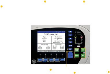
The MX350 is equipped with a graphical control panel:
•Includes a 89 mm (3.5-inch) 320 by 240 pixel backlit colour LCD screen, 15 pushbuttons, and 7 LED indicators, which provide access to actual values, fault and alarm lists, event records, and setting configuration. A USB port is provided for laptop computer connection.
Figure 2: MX350 feature overview
|
|
|
|
|
Graphical display |
|
|
|
|
LED indication |
||
|
|
|
|
|
• Large metering values |
|
|
|
|
• Time delay indication |
||
|
Ease of use |
|
• Wide viewing angle |
|
|
|
|
• Alarm indication |
||||
|
|
|
|
|
|
|
|
|
||||
|
• Graphical interface |
|
|
|
|
|
|
|
|
|
||
|
|
|
|
|
|
|
|
|
|
|
|
• Transfer inhibit indication |
|
• Self-description |
|
|
|
|
|
|
|
|
|
||
|
|
|
|
|
|
|
|
|
|
|
|
• Source available & connected |
|
|
|
|
|
|
|
|
|
|
|
|
indication |
|
|
|
|
|
|
|
|
|
|
|
|
|
Mounting options |
|
|
|
|
|
|
|
|
|
|
||
• DIN Rail |
|
|
|
|
|
|
|
|
|
|
|
|
• Through door |
|
|
|
|
|
|
|
|
|
|||
|
|
|
|
|
|
|
|
|
|
|
|
|
|
|
|
|
|
|
|
|
|
|
|
|
|
|
|
|
|
|
|
|
|
|
|
|
|
|
Integrated functionality |
|
|
|
|
|
|
|
|
|
|
|
|
|
|
|
|
|
|
|
|
|
|
|
|
|
|
|
|
|
|
|
|
|
|
|
• Metering, control |
|
|
|
|
|
|
|
|
|
|
|
|
|
|
|
|
|
|
|
|
|
|
|
• Event recorder |
|
|
|
|
|
|
|
|
|
|
Front panel control |
|
|
|
|
|
|
|
|
|
|
||
Soft key navigation |
|
|
Front port access |
||||||||
|
|
|
|
||||||||
|
• Graphical module control |
|
|
• USB for laptop connection |
• Integrated device control |
||||||
|
|
|
|
||||||||
|
|
|
|
|
|
|
|
|
|
|
• Dedicated control keys |
|
|
|
|
|
|
|
|
|
|
|
889723A1.CDR |
The MX350 includes the following input/output capabilities:
•5 to 25 contact outputs
•5 to 32 contact inputs
The following option packages are available:
Option A:
•Full function ATS control with full sensing and control capabilities, depending on order option.
•Expanded diagnostics, high-speed 256-event capture, 365-day exerciser, EnerVista launchpad, USB interface for uploading and downloading setup parameters
•4 programmable inputs and 4 outputs assignable to additional ATS features
•Full complement of programmable ATS control switches (AUTO/MAN, Preferred Source selector, Commit/No Commit Xfer, Transition Mode Select (for Closed Transition switch models).
Option B:
Option Package A plus:
•10 customer programmable digital and 10 analog alarms
1–2 |
MX350 AUTOMATIC TRANSFER CONTROL SYSTEM – INSTRUCTION MANUAL |
CHAPTER 1: INTRODUCTION |
OVERVIEW |
•20 channel data logger, customer configurable sample period from 1 cycle to 60 minutes
•Waveform capture, 10 channels, up to 256 cycles each 16 samples/sec
•Auto Load Shed with voltage, frequency and kW triggers
Option C:
Option Package B plus:
•4 additional inputs and outputs (total 8 in, 8 out
Option D:
Option Package C plus:
•4 additional inputs and outputs (total - 12 in, 12 out)
•FlexLogic for user-customized control logic
Option M:
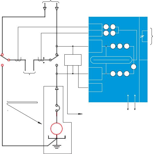
• Configuration for Manual operation only (non-Automatic) A single-line diagram for the MX350 is shown below.
MX350 AUTOMATIC TRANSFER CONTROL SYSTEM – INSTRUCTION MANUAL |
1–3 |
OVERVIEW |
CHAPTER 1: INTRODUCTION |
Figure 3: Single line diagram
TO
UTILITY (SOURCE-1)
NOTE:1
NOTE:1
X1 
H1 (1) CT
NOTE:1
TO LOAD
SUPPLIED BY OTHERS
NOTE:1
|
|
|
CT CARD |
|
|
|
|
K |
|
|
|
|
|
|
|
|
|
|
|
|
|
|
|
|
|
CARD |
|
|
|
NEUTRAL |
50G |
51G |
|
|
|
|
|
|
METERING |
51R |
46 |
|
|
|
|
|
|
|
|
|
|
|
P |
|
|
|
VOLTAGE |
|
|
|
|
|
|
|
|
CARD |
|
27 |
59 |
47 |
|
|
|
|
SOURCE |
|
|
|||
|
|
|
|
|
|
|
|
|
|
|
|
1 |
|
|
|
|
|
|
X1 |
UTA |
|
METERING |
|
|
|
|
|
|
|
|
|
|
|||
|
|
V, A, W, VAR, VA, PF, HZ |
|
|
||||
|
H1 |
|
|
|
||||
(3) |
|
|
|
|
|
|
I/O |
|
|
|
|
|
|
|
|
||
CT'S |
|
|
VOLTAGE |
|
|
|
25 |
CARD |
|
|
|
|
|
|
|
|
|
|
|
|
CARD |
|
27 |
59 |
47 |
|
|
|
|
SOURCE |
|
|
|||
|
|
|
|
|
|
|
|
|
|
|
|
2 |
|
|
|
|
|
|
|
|
POWER |
|
|
|
170VDC |
SUPPLY |
|
|
|
|
|
|
|
|
|
ATS |
|
|
|
|
CONTROLLER |
|
|
|
TO K CARD |
TCP/IPMODBUS-ETHERNET |
|
|
24VDC |
|
RTUMODBUS-RS485 |
|
|
|
|
|
|
|
|
|
AND |
|
|
|
I/O CARD |
|
|
GEN |
|
|
|
|
SOURCE-2
ENGINE START CONTACT
889739A1.CDR
NOTE:1- FOURTH POLE/NEUTRAL POLE IS AN OPTIONAL FEATURE.
Table 1: MX350 protection functions
ANSI device |
Description |
|
|
25 |
Synch check |
|
|
27 |
Undervoltage |
|
|
46 |
Current balance |
|
|
47 |
Voltage phase reversal |
|
|
50G (option) |
Ground instantaneous overcurrent |
|
|
51G (option) |
Ground time overcurrent |
|
|
51 (option) |
Overcurrent |
|
|
59 |
Overvoltage |
|
|
1–4 |
MX350 AUTOMATIC TRANSFER CONTROL SYSTEM – INSTRUCTION MANUAL |
CHAPTER 1: INTRODUCTION |
OVERVIEW |
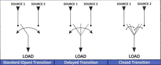
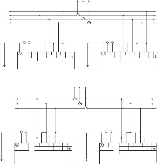
ATS types
Automatic Transfer switch types to be controlled by the Controller are Standard (Open) Transition, Delayed Transition, and Closed Transition. The figure below shows the one-line diagram for all three types.
Figure 4: Automatic transfer switch types
In addtion, the MX350 can control the Bypass/Isolation type version of the three basic ATS types.
MX350 AUTOMATIC TRANSFER CONTROL SYSTEM – INSTRUCTION MANUAL |
1–5 |

SPECIFICATIONS |
CHAPTER 1: INTRODUCTION |
Specifications
Specifications are subject to change without notice.
NOTE
Timing specifications
GENERAL TIMING ACCURACY
Accuracy:................................................................ |
±500 ms |
Protection specifications
OVERVOLTAGE
Pickup level:........................................................... |
1.05 to 1.10 × VT in steps of 0.01 (programmable) |
Dropout: .................................................................. |
1.03 to 1.08 × VT in steps of 0.01 (programmable) |
Time delay: ............................................................ |
No programmable time delay |
UNDERVOLTAGE
Pickup level:........................................................... |
0.75 to 0.99 × VT in steps of 0.01 (programmable) |
Dropout: .................................................................. |
0.85 to 1.00 × VT in steps of 0.01 (programmable) |
Time delay: ............................................................ |
No programmable time delay |
OVERFREQUENCY
Pickup level:........................................................... |
50.1 to 63.0 Hz in steps of 0.1 (programmable) |
Dropout: .................................................................. |
50.0 to 62.9 Hz in steps of 0.1 (programmable) |
Time delay: ............................................................ |
No programmable time delay |
Accuracy:................................................................ |
±0.05 Hz |
UNDERFREQUENCY
Pickup level:........................................................... |
45.0 to 59.9 Hz in steps of 0.1 (programmable) |
Dropout: .................................................................. |
45.1 to 60.0 Hz in steps of 0.1 (programmable) |
Time delay: ............................................................ |
No programmable time delay |
Accuracy:................................................................ |
±0.05 Hz |
POWER FACTOR
Pickup level:........................................................... |
0.99 lag to 0.99 lead in steps of 0.01 (programmable) |
Dropout: .................................................................. |
pickup + hysteresis |
Time delay: ............................................................ |
0 to 65535 seconds in steps of 1 |
Accuracy:................................................................ |
±0.05 |
VOLTAGE IMBALANCE
Pickup level:........................................................... |
0.05 to 0.20 in steps of 0.01 (programmable) |
Dropout: .................................................................. |
0.03 to 0.18 in steps of 0.01 (programmable) |
Time delay: ............................................................ |
1 to 60 seconds in steps of 1 |
CURRENT IMBALANCE
Range:...................................................................... |
4 to 40% in steps of 1 |
Pickup level:........................................................... |
0.04 to 0.40 in steps of 0.01 (programmable) |
Time delay: ............................................................ |
1 to 60 seconds in steps of 1 s |
Timing accuracy: ................................................ |
±500 ms |
Elements:................................................................ |
alarm |
Accuracy:................................................................ |
±2% |
1–6 |
MX350 AUTOMATIC TRANSFER CONTROL SYSTEM – INSTRUCTION MANUAL |
CHAPTER 1: INTRODUCTION SPECIFICATIONS
CALCULATION METHOD
( [IM - IAV] / IAV ) x 100%
Where:
IAV = average phase current
IM = current in a phase with maximum deviation from IAV
THD ALARM (CURRENT/VOLTAGE)
Pickup level: ........................................................... |
0.1% to 100.0% in steps of 0.1% (programmable) |
Time delay:............................................................. |
0 to 65535 seconds in steps of 1 |
OVERCURRENT (PER PHASE/NEUTRAL)
Pickup level: ........................................................... |
0.01 to 2.00 × Nominal Current in steps of 0.01% |
|
(programmable) |
Time delay:............................................................. |
0 to 65535 seconds in steps of 1 |
User interface specifications
GRAPHICAL CONTROL PANEL
Size: ........................................................................... |
height 102mm, width 153mm, depth 35mm |
LCD: ........................................................................... |
89 mm (3.5-inch) colour, 320 by 240 pixels |
LED indicators: ..................................................... |
7 LEDs |
Pushbuttons: ......................................................... |
Alarm Reset, Test, Ctrl, Info, plus 11 LCD screen display |
|
control keys |
Ports:......................................................................... |
USB 2.0 type Mini-B for laptop computer connection |
Metering and monitoring specifications
EVENT RECORDER
Capacity: ................................................................. |
256 events |
Data storage:........................................................ |
non-volatile memory |
FREQUENCY METERING
Range: ...................................................................... |
40.00 to 70.00 Hz in steps of 0.01 |
Accuracy: ................................................................ |
±0.05 Hz |
POWER METERING
Real power range: .............................................. |
–2000.0 to 2000.0 kW in steps of 0.1 |
Apparent power range:.................................... |
0.0 to 2500.0 kVA in steps of 0.1 |
Accuracy: ................................................................ |
±2.0% of full scale with 5 A CT |
POWER FACTOR METERING
Range: ...................................................................... |
–0.99 to +0.99 in steps of 0.01 |
Accuracy: ................................................................ |
±0.05 |
Inputs specifications
CONTROL VOLTAGE INPUT
Input range: ........................................................... |
60 V to 300 V AC |
Nominal frequency: ........................................... |
50 or 60 Hz |
DIGITAL INPUTS
Nominal input voltage:..................................... |
24 V DC |
Recognition time:................................................ |
2 cycles |
Continuous current draw:............................... |
4 mA |
Type:.......................................................................... |
opto-isolated inputs |
External switch: ................................................... |
wet contact |
MX350 AUTOMATIC TRANSFER CONTROL SYSTEM – INSTRUCTION MANUAL |
1–7 |

SPECIFICATIONS |
CHAPTER 1: INTRODUCTION |
PHASE CURRENT INPUTS
Range:...................................................................... |
2.5 to 7.5 A (1.5 × CT) |
Input type:.............................................................. |
5 A |
Frequency: ............................................................. |
50 or 60 Hz |
Accuracy:................................................................ |
±2.0% of Full Scale, where Full Scale = 1.5 × CT Primary |
Withstand (at 5A nominal):............................. |
0.2 s at 100× |
|
1.0 s at 50× |
|
2.0 s at 40× |
|
continuous at 3× rated current |
PHASE VOLTAGE INPUTS (THREE-PHASE VOLTAGE)
Input range:........................................................... |
120 to 600 V (nominal) |
Nominal frequency: ........................................... |
50 or 60 Hz |
Accuracy:................................................................ |
±2% of reading, or ±1 V, whichever is greater |
Phase current Input Type of 1 A is not supported.
NOTE
Outputs specifications
FORM-C RELAY
Contact material:................................................ |
silver-alloy |
Operate time:........................................................ |
10 ms |
Maximum contact load: .................................. |
10 mA at 5 V DC |
Maximum switching rate:............................... |
300 operations per minute (no load), 30 operations per |
|
minute (load) |
Mechanical life:.................................................... |
10 000 000 operations |
Continuous current:........................................... |
10 A |
Make and carry for 0.2s:.................................. |
30 A per ANSI C37.90 |
FORM-C OUTPUT RELAY BREAK CAPACITY
AC resistive, 120 V AC: ...................................... |
10 |
A normally-open, 5 A normally-closed |
AC resistive, 240 V AC: ...................................... |
10 |
A normally-open, 8 A normally-closed |
AC inductive, PF = 0.4 pilot duty:.................. |
2.5 A |
|
DC resistive, 30 V DC: ........................................ |
10 |
A |
SOLID STATE OUTPUT RELAY
Operate time:........................................................ |
< 1 ms |
Nominal voltage:................................................. |
24 V DC |
Maximum current:.............................................. |
0.5 A |
Power supply specifications
POWER SUPPLY
Nominal:.................................................................. |
120 to 240 V AC |
|
125 to 250 V DC |
Range:...................................................................... |
60 to 300 V AC (50 and 60 Hz) |
|
84 to 250 V DC |
Ride-Through:....................................................... |
35 ms |
ALL RANGES
Voltage withstand:............................................. |
2 × highest nominal voltage for 10 ms |
Power consumption: ......................................... |
16 W typical, 25 W maximum |
1–8 |
MX350 AUTOMATIC TRANSFER CONTROL SYSTEM – INSTRUCTION MANUAL |
CHAPTER 1: INTRODUCTION |
SPECIFICATIONS |
Communications specifications
ETHERNET (COPPER)
Modes:...................................................................... |
10/100 MB (auto-detect) |
Connector:.............................................................. |
RJ-45 |
SNTP clock synchronization error: .............. |
<200 ms (typical) |
Protocol: .................................................................. |
Modbus TCP |
RS485 PORT
Port: ........................................................................... |
opto-isolated |
Baud rates:............................................................. |
up to 115 kbps |
Protocol: .................................................................. |
Modbus RTU, half-duplex |
Maximum distance: ........................................... |
1200 m |
Isolation:.................................................................. |
2 kV |
USB PORT
Standard specification:.................................... |
Compliant with both USB 2.0 and USB 1.1 |
|
Data transfer rate:.............................................. |
USB device emulating serial communications port at |
|
|
115 kbps |
|
Connector:.............................................................. |
USB2.0 Mini-B |
|
Testing and certification |
|
|
TESTING AND CERTIFICATION |
|
|
Test |
Reference Standard |
Test Level |
Dielectric Voltage Withstand: |
EN60255-5 |
2.0 KV |
Impulse Voltage Withstand: |
EN60255-5 |
5 KV |
Insulation Resistance: |
EN60255-5 |
500 V DC > 100 Mohm |
Damped Oscillatory: |
IEC61000-4-18/IEC60255-22-1 |
2.5 KV CM, 1 KV DM |
Electrostatic Discharge: |
EN61000-4-2/IEC60255-22-2 |
Level 4 |
RF Immunity: |
EN61000-4-3/IEC60255-22-3 |
Level 3 |
Fast Transient Disturbance: |
EN61000-4-4/IEC60255-22-4 |
Level 4 |
Surge Immunity: |
EN61000-4-5/IEC60255-22-5 |
Level 3 & 4 |
Conducted RF Immunity: |
EN61000-4-6/IEC60255-22-6 |
Level 3 |
Power magnetic Immunity: |
IEC61000-4-8 |
Level 4 |
Voltage Dip & Interruption: |
IEC61000-4-11 |
0,40,70% dips 250/300cycle |
|
|
interrupts |
Radiated & Conducted Emissions: |
CISPR11 /CISPR22/ IEC60255-25 |
Class A |
Ingress Protection: |
IEC60529 |
IP20 (base unit) IP54 (Control |
|
|
Panel) |
Environmental (Cold): |
IEC60068-2-1 |
-20oC 16 hrs |
Environmental (Dry heat): |
IEC60068-2-2 |
85oC 16hrs |
Relative Humidity Cyclic: |
IEC60068-2-30 |
6-day variant 2 |
Fast Transient Disturbance: |
IEEE C37.90.1 |
4 KV CM & DM |
SWC Damped Oscillatory: |
IEEE C37.90.1 |
2.5 KV CM |
Electrostatic Discharge: |
IEEE C37.90.3 |
8 KV CD, 15 KV AD |
MX350 AUTOMATIC TRANSFER CONTROL SYSTEM – INSTRUCTION MANUAL |
1–9 |
SPECIFICATIONS |
CHAPTER 1: INTRODUCTION |
APPROVALS |
|
|
|
Applicable Council Directive |
According to |
CE compliance: |
Low voltage directive |
EN60255-5, EN60947-1, EN60947-6-1 |
|
EMC Directive |
EN61000-6-2/ EN61000-6-4 |
ISO: |
Manufactured under a registered |
ISO9001 |
|
quality program |
|
Physical specifications
DIMENSIONS
Size: ........................................................................... |
Base: 62 mm [2.44"] (W) × 90 mm [3.54"] (H) × 113 mm [4.45"] |
|
(D) (+ terminals 10mm [0.39"]) |
|
Expansion: 62 mm [2.44"] (W) × 90 mm [3.54"] (H) × 113 mm |
|
[4.45"] (D) |
|
GCP: 153 mm [6.02"] (W) × 102 mm [4.02"] (H) × 35 mm [1.38"] |
|
(D) |
Weight (Base):....................................................... |
0.75 kg [1.65 lb] |
Environmental specifications |
|
ENVIRONMENTAL SPECIFICATIONS |
|
Ambient temperatures: |
|
Storage/shipping: |
- 40oC to 90oC * |
Operating: |
-20oC to 60oC * (Base Unit and Basic Control Panel) |
|
-20oC to 50oC * (Graphical Control Panel) |
* 1" around Base Unit |
|
Humidity: |
Operating up to 95% (non condensing) @ 55oC (As |
|
per IEC60068-2-30 Variant 2, 6days) |
Altitude: |
2000 m (max) |
Overvoltage Category: |
II |
Ingress Protection: |
IP20 (Base Unit), IP54 (Control Panel) |
1–10 |
MX350 AUTOMATIC TRANSFER CONTROL SYSTEM – INSTRUCTION MANUAL |
CHAPTER 1: INTRODUCTION |
ORDER CODES FOR MX350 |
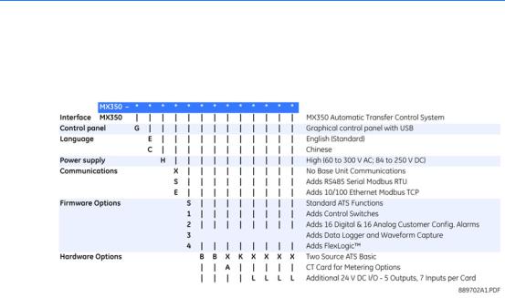
Order codes for MX350
The information to specify an MX350 relay is provided in the following order code figure.
Figure 5: MX350 order codes
Example of an MX350 order code
MX350-GEHE3BBAKLL: MX350 with graphical control panel incl. USB port, English language display, high voltage control power supply (84 to 250 VDC or 60 to 300VAC), RS485 Modbus RTU port and 10/100 Modbus TCP/IP Ethernet port), data logger and waveform capture, source 1 voltage sensing, source 2 voltage sensing, load current sensing, P relay function, and two input/output cards.
MX350 AUTOMATIC TRANSFER CONTROL SYSTEM – INSTRUCTION MANUAL |
1–11 |
ORDER CODES FOR MX350 |
CHAPTER 1: INTRODUCTION |
1–12 |
MX350 AUTOMATIC TRANSFER CONTROL SYSTEM – INSTRUCTION MANUAL |

Digital Energy
Multilin
MX350 Automatic Transfer Control
System
Chapter 2: Installation
Mechanical installation
This section describes the mechanical installation of the MX350 system, including dimensions for mounting and information on module withdrawal and insertion.
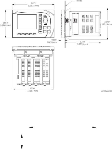
Dimensions
The MX350 is packaged in a modular arrangement.
The dimensions of the MX350 are shown below. Additional dimensions for mounting and panel cutouts are shown in the following sections.
MX350 AUTOMATIC TRANSFER CONTROL SYSTEM – INSTRUCTION MANUAL |
2–1 |
MECHANICAL INSTALLATION |
CHAPTER 2: INSTALLATION |
Figure 1: MX350 dimensions
Product identification
The product identification label is located on the side panel of the MX350. This label indicates the product model, serial number, firmware revision, and date of manufacture.
Figure 2: MX350 label
|
|
|
|
|
|
|
|
|
|
|
|
|
|
|
|
|
|
|
|
|
2.425” |
|
|
|||||||||||||||||
|
|
|
|
|
|
|
|
|
|
|
|
|
|
|
|
|
|
|
(61.6 mm) |
|
||||||||||||||||||||
|
|
|
|
|
|
|
|
|
|
|
|
|
|
|
|
|
|
|
|
|
|
|
|
|
|
|
|
|
|
|
|
|
|
|
|
|
|
|
|
|
|
|
|
|
|
|
|
|
|
|
|
|
|
|
|
|
|
|
|
|
|
|
|
|
|
|
|
|
|
|
|
|
|
|
|
|
|
|
|
|
|
|
|
|
|
|
Model: |
|
|
|
|
|
|
|
|
|
|
|
|
|
|
|
|
|
|
|
|
|
|
|||||||||||||
|
|
|
|
|
Serial Number: |
|
|
|
|
|
|
|
|
|
|
|
|
|
|
|
|
|
|
|
|
|
|
|||||||||||||
|
|
|
|
|
Firmware: |
|
|
|
|
Mfg. Date: |
|
|||||||||||||||||||||||||||||
|
|
|
|
|
|
|
|
|
|
|
|
|
|
|
|
|
|
|
|
|
|
|
|
|
|
|
|
|
|
|
|
|
|
|
|
|
|
|
|
|
|
|
|
|
|
|
|
|
|
|
|
|
|
|
|
|
|
|
|
|
|
|
|
|
|
|
|
|
|
|
|
|
|
|
|
|
|
|
|
|
|
|
|
|
|
|
|
|
|
|
|
|
|
|
|
|
|
|
|
|
|
|
|
|
|
|
|
|
|
|
|
|
|
|
|
|
|
|
|
|
|
|
0.525” |
|
|
|
|
|
|
|
|
|
|
|
|
|
|
|
|
|
889748A1.CDR |
||||||||||||||||||||||
(13.3 mm) |
|
|
|
|
|
|
|
|
|
|
|
|
|
|
|
|
|
|
|
|
|
|
||||||||||||||||||
Mounting
The MX350 can be mounted three ways: standard panel mount, DIN rail mount, and screw mount for high vibration environments.
The standard panel mount and cutout dimensions are illustrated below.
2–2 |
MX350 AUTOMATIC TRANSFER CONTROL SYSTEM – INSTRUCTION MANUAL |

CHAPTER 2: INSTALLATION |
MECHANICAL INSTALLATION |
Figure 3: Panel mounting and cutout dimensions
#4 - 40x3/8in SELF-TAP PAN HD PHILIPS QTY: 6 (SUPPLIED); GE PART NO. 1402-0017 TIGHTENING TORQUE: 8 lb-in
INSTALL RELAY |
REAR OF PANEL |
FROM FRONT |
|
OF THE PANEL |
|
|
CUTOUT AND |
|
MOUNTING HOLES |
5.580” |
0.105” |
(141,73 mm) |
(2,67 mm) |
|
0.138” |
|
(3,49 mm) |
|
1.750” |
|
(44,45 mm) |
3.775”
(95,89 mm) 3.500”
(88,90 mm)
5.790”
(147,07 mm)  0.130” (QTY: 6)
(3,30 mm)
889725A1.CDR
The DIN rail mounting is illustrated below. The DIN rail conforms to EN 50022.
To avoid the potential for personal injury due to fire hazards, ensure the unit is mounted in a safe location and/or within an appropriate enclosure.
CAUTION
Figure 4: DIN rail mounting
SNAP-IN THE DIN CLIPS (QTY: 4)
FOR DIN RAIL MOUNTING
0.30” (7,6 mm)
1.38” (35,1 mm)
DIN 3 RAIL
889726A1.CDR
The screw mount for high vibration environments is illustrated below.
MX350 AUTOMATIC TRANSFER CONTROL SYSTEM – INSTRUCTION MANUAL |
2–3 |
MECHANICAL INSTALLATION |
CHAPTER 2: INSTALLATION |
Figure 5: Screw mounting
MEETS VIBRATION REQUIREMENT OF
IEC 60255 SEC 21.1, 21.2, & 21.3
2.250” (57,15 mm)
#6 -32 THREADED HOLE
QTY: 2
4.100” (104,14 mm)
889727A1.CDR
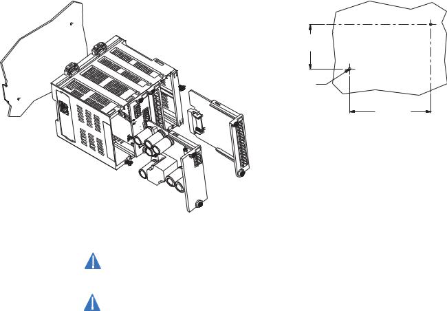
Module withdrawal and insertion
DANGER
CAUTION
Module withdrawal and insertion may only be performed when control power has been removed from the unit. Inserting an incorrect module type into a slot may result in personal injury, damage to the unit or connected equipment, or undesired operation!
Proper electrostatic discharge protection (for example, a static strap) must be used when coming into contact with modules while they are removed from the MX350.
The MX350 is a modular protection system. This allows for easy withdrawal and insertion of modules for fast replacement. Modules must only be replaced in their original factory configured slots.
Use the following procedure to withdraw a module.
1.Ensure that control power has been removed from the MX350.
2.Record the slot location of the module to ensure that the same or replacement module is inserted into the correct slot.
3.Remove the two captive screws at the top and bottom of the module.
4.Slide a flat-blade screwdriver into the opening above the module marked by the two arrows on top of the MX350 case.
5.Press down on the screwdriver and pivot towards the unit to unlatch the module from the MX350 case.
2–4 |
MX350 AUTOMATIC TRANSFER CONTROL SYSTEM – INSTRUCTION MANUAL |
CHAPTER 2: INSTALLATION |
MECHANICAL INSTALLATION |
Figure 6: Removing a module from the MX350
889733A1.CDR
Use the following procedure to insert a module.
1.Ensure that control power has been removed from the MX350.
2.Ensure that the module is being inserted into the correct slot.
3.Align the module card edges with the slot track as shown in the diagram below.
4.Gently slide the modules into the slot until the modules latch into the opening marked by the two arrows on top of the MX350 case.
5.Attach the two captive screws to anchor the module to the case (use a tightening torque of 3.5 lb.-in.).
Figure 7: Inserting modules into the MX350
889734A1.CDR
MX350 AUTOMATIC TRANSFER CONTROL SYSTEM – INSTRUCTION MANUAL |
2–5 |

MECHANICAL INSTALLATION |
CHAPTER 2: INSTALLATION |
Module and terminal identification
The MX350 input/output and metering modules are labeled with the “IO_” prefix followed by a one-character identifier as follows.
Table 1: Input/output and metering module nomenclature
Module |
Description |
|
|
IO_A |
CT module |
|
|
IO_B |
VT module |
|
|
IO_K |
4 inputs, 4 outputs, plus relay for engine control |
|
|
IO_L |
7 inputs, 5 outputs |
|
|
NOTE
The MX350 terminals are labeled with a two-character identifier. The first character identifies the module slot position and the second character identifies the terminals within the module. For example, the first terminal in a module in slot F is identified as “F1”.
Do not confuse the slot designation with the module ordering designation. That is, terminal “F1” does not imply an IO_F module. Rather, it indicates the first terminal of whatever module is in slot F, which can only be an IO_K module.
2–6 |
MX350 AUTOMATIC TRANSFER CONTROL SYSTEM – INSTRUCTION MANUAL |

CHAPTER 2: INSTALLATION |
ELECTRICAL INSTALLATION |
Electrical installation
Reserved
Switched power supply
allows AC or DC control voltage
Optional TCP/IP
Ethernet
This section describes the electrical installation of the MX350 system. An overview of the MX350 terminal connections is shown below.
Figure 8: MX350 terminal connection overview
|
Three-phase plus |
Expansion module |
|
Expansion module |
|
|
to base unit with a |
|
to base/expansion unit |
|
|
|
ground/neutral |
|
|
||
|
single connector |
|
with a single connector |
|
|
RS485 communications |
VT inputs |
K Card |
|
||
|
|
|
|||
|
|
CT Input |
|
L Card |
L Card |
889740A2.CDR
Reserved |
Expansion module |
Expansion module |
The MX350 can contain up to ten modules. The first four modules (slots A through D) reside in the base unit while all subsequent modules (slots E and J) reside in expansion units. Each expansion unit can contain up to two modules. Slots A through G make up the basic MX350. The next three modules (slots H through J) are optional I/O modules.
Table 2: Module slot position
Slot |
Module types |
|
|
A |
Power supply module |
|
|
B |
CPU module with communications |
|
|
C |
IO_B module |
|
|
D |
IO_B module |
|
|
E |
IO_A module (optional) |
|
|
F |
IO_K module |
|
|
G |
IO_L module |
|
|
H |
IO_L module (optional) |
|
|
I |
IO_L module (optional) |
|
|
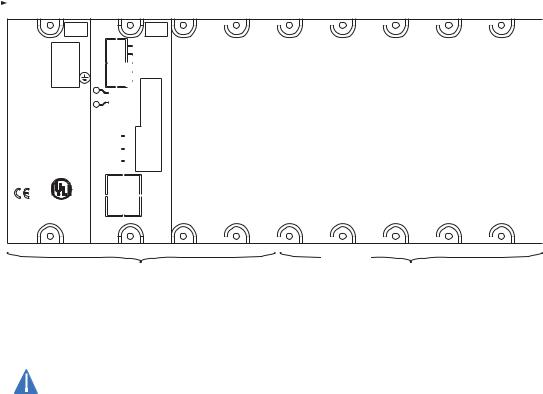
The following figure shows a typical module arrangement for an expanded unit.
Use gauge size appropriate for the voltage and current draw of the device.
CAUTION |
The MX350 is not to be used in any way other than described in this manual. |
MX350 AUTOMATIC TRANSFER CONTROL SYSTEM – INSTRUCTION MANUAL |
2–7 |
ELECTRICAL INSTALLATION |
CHAPTER 2: INSTALLATION |
Figure 9: Typical module arrangement
Slot position |
|
A |
B |
C |
D |
E |
F |
G |
H |
I |
|
|
L |
V- |
PSU |
|
L |
60-300 VAC |
N |
C |
84-250 VDC |
|
H |
|
|
V+ |
|
|
MS |
|
|
NS |
|
|
GROUND CT I/P |
|
E200434 |
|
LISTED
IND.CONT.EQ.
52TL

 THERM RS485 FIELD BUS
+
–
C
+
–
SG
R
I
10/100  ETHERNET
|
|
|
|
|
|
|
|
|
|
|
|
|
|
|
|
|
|
|
|
|
|
|
|
|
|
|
|
|
|
|
|
|
|
|
|
|
|
|
|
|
|
|
|
|
|
|
|
|
|
|
|
|
|
|
|
|
|
|
|
|
|
|
|
|
|
|
|
|
|
|
|
|
|
|
|
|
|
|
|
|
|
|
|
|
|
|
|
|
|
|
|
|
|
|
|
|
|
|
|
|
|
|
|
|
|
14 |
|
|
|
|
14 |
|
|
|
|
14 |
|
|
|
|
14 |
||||
|
|
|
|
|
|
|
|
|
|
|
|
|
|
|
|
|
|
|
|
|
|
|
|
|
|
|
|
|
|
|
|||||||||||
|
|
8 |
|
|
|
|
8 |
|
|
|
|
|
8 |
|
|
|
|
|
13 |
|
|
|
13 |
|
|
|
13 |
|
|
|
13 |
||||||||||
|
|
|
|
|
|
|
|
|
|
|
|
|
|
|
|
|
|
|
|
|
|
|
|
|
|
|
|
|
|
|
|||||||||||
|
|
|
|
|
|
|
|
|
|
|
|
|
|
|
|
|
|
|
|
|
|
12 |
|
|
|
12 |
|
|
|
12 |
|
|
|
12 |
|||||||
|
|
7 |
|
|
7 |
|
|
7 |
|
|
|
|
|
11 |
|
|
|
|
11 |
|
|
|
|
11 |
|
|
|
|
11 |
||||||||||||
|
|
|
|
|
|
|
|
|
|
|
|
|
|
|
|
|
|
|
|
|
|
|
|
|
|
|
|
|
|
|
|||||||||||
|
|
6 |
|
|
|
|
6 |
|
|
|
|
|
6 |
|
|
|
|
|
10 |
|
|
|
10 |
|
|
|
10 |
|
|
|
10 |
||||||||||
|
|
|
|
|
|
|
|
|
|
|
|
|
|
|
|
|
|
|
|
|
|
|
|
|
|
|
|
|
|
|
|||||||||||
|
|
|
|
|
|
|
|
|
|
|
|
|
|
|
|
|
|
|
|
|
|
9 |
|
|
|
9 |
|
|
|
9 |
|
|
|
9 |
|||||||
|
|
5 |
|
|
5 |
|
|
5 |
|
|
|
|
|
8 |
|
|
|
|
8 |
|
|
|
|
8 |
|
|
|
|
8 |
||||||||||||
|
|
|
|
|
|
|
|
|
|
|
|
|
|
|
|
|
|
|
|
|
|
|
|
|
|
|
|
|
|
|
|||||||||||
|
|
4 |
|
|
|
|
4 |
|
|
|
|
|
4 |
|
|
|
|
|
7 |
|
|
|
7 |
|
|
|
7 |
|
|
|
7 |
||||||||||
|
|
|
|
|
|
|
|
|
|
|
|
|
|
|
|
|
|
|
|
|
|
|
|
|
|
|
|
|
|
|
|||||||||||
|
|
|
|
|
|
|
|
|
|
|
|
|
|
|
|
|
|
|
|
|
|
6 |
|
|
|
6 |
|
|
|
6 |
|
|
|
6 |
|||||||
|
|
3 |
|
|
3 |
|
|
3 |
|
|
|
|
|
5 |
|
|
|
|
5 |
|
|
|
|
5 |
|
|
|
|
5 |
||||||||||||
|
|
|
|
|
|
|
|
|
|
|
|
|
|
|
|
|
|
|
|
|
|
|
|
|
|
|
|
|
|
|
|||||||||||
|
|
2 |
|
|
|
|
2 |
|
|
|
|
|
2 |
|
|
|
|
|
4 |
|
|
|
4 |
|
|
|
4 |
|
|
|
4 |
||||||||||
|
|
|
|
|
|
|
|
|
|
|
|
|
|
|
|
|
|
|
|
|
|
|
|
|
|
|
|
|
|
|
|||||||||||
|
|
|
|
|
|
|
|
|
|
|
|
|
|
|
|
|
|
|
|
|
|
3 |
|
|
|
3 |
|
|
|
3 |
|
|
|
3 |
|||||||
|
|
1 |
|
|
1 |
|
|
1 |
|
|
|
|
|
2 |
|
|
|
|
2 |
|
|
|
|
2 |
|
|
|
|
2 |
||||||||||||
|
|
|
|
|
|
|
|
|
|
|
|
|
|
|
|
|
|
|
|
|
|
|
|
|
|
|
|
|
|
|
|||||||||||
|
|
|
|
|
|
|
|
|
|
|
|
|
|
|
|
|
|
|
|
|
|
1 |
|
|
|
1 |
|
|
|
1 |
|
|
|
1 |
|||||||
|
|
|
|
|
|
|
|
|
|
|
|
|
|
|
|
|
|
|
|
|
|
|
|
|
|
|
|
|
|
|
|
|
|
|
|
|
|
|
|
|
|
|
|
|
|
|
|
|
|
|
|
|
|
|
|
|
|
|
|
|
|
|
|
|
|
|
|
|
|
|
|
|
|
|
|
|
|
|
|
|
|
|
|
|
|
|
|
|
|
|
|
|
|
|
|
|
|
|
|
|
|
|
|
|
|
|
|
|
|
|
|
|
|
|
|
|
|
|
|
|
|
|
|
|
|
|
|
|
|
|
|
|
|
|
|
|
|
|
|
|
|
|
|
|
|
|
|
|
|
|
|
|
|
|
|
|
|
|
|
|
|
|
|
|
|
|
|
Base unit |
Expansion modules |
889749A1.CDR
Power supply module
The power supply module in slot A supplies control power to the MX350 system. A supply voltage between 60 to 300 V AC or 84 to 250 V DC is required to power the MX350
Check the voltage rating of the unit before applying control power! Control power outside of the operating range of the power supply will damage the MX350.
CAUTION
2–8 |
MX350 AUTOMATIC TRANSFER CONTROL SYSTEM – INSTRUCTION MANUAL |

CHAPTER 2: INSTALLATION |
ELECTRICAL INSTALLATION |
CPU module
RS485 connections
CAUTION
The main CPU module and optional communications board is contained in slot B. The main CPU module provides a Modbus RTU RS485 port. The optional communications board provides an Ethernet port.
Figure 10: Typical RS485 connection
ZT (*)
OPTOCOUPLER
DATA |
COM |
|
SCADA, PLC, OR
PERSONAL COMPUTER
GROUND THE SHIELD AT THE
SCADA/PLC/COMPUTER ONLY
OR THE UNIT ONLY
(*)TERMINATING IMPEDANCE AT EACH END (typically 120 ohms and 1 nF)
|
TWISTED PAIR |
IED |
|
SHIELD |
|
||
B1 |
RS485 + |
||
|
|||
|
|
OPTOCOUPLER |
|
|
B2 |
RS485 - |
DATA
B3 COMMON
UP TO 32 IEDs, MAXIMUM CABLE LENGTH OF 1200 m (4000 ft.)
|
IED |
RS485 + |
|
RS485 - |
|
COMMON |
|
|
IED |
ZT (*) |
|
RS485 + |
|
RS485 - |
|
|
LAST |
COMMON |
DEVICE |
889745A1.CDR
One two-wire RS485 port is provided. Up to 32 MX350 IEDs can be daisy-chained together on a communication channel without exceeding the driver capability. For larger systems, additional serial channels must be added. Commercially available repeaters can also be used to add more than 32 relays on a single channel. Suitable cable should have a characteristic impedance of 120 ohms (for example, Belden #9841) and total wire length should not exceed 1200 meters (4000 ft.). Commercially available repeaters will allow for transmission distances greater than 1200 meters.
Voltage differences between remote ends of the communication link are not uncommon. For this reason, surge protection devices are internally installed across all RS485 terminals. Internally, an isolated power supply with an optocoupled data interface is used to prevent noise coupling.
To ensure that all devices in a daisy-chain are at the same potential, it is imperative that the common terminals of each RS485 port are tied together and grounded only once, at the master or at the MX350. Failure to do so may result in intermittent or failed communications.
The source computer/PLC/SCADA system should have similar transient protection devices installed, either internally or externally. Ground the shield at one point only, as shown in the figure above, to avoid ground loops.
Correct polarity is also essential. The MX350 IEDs must be wired with all the positive (+) terminals connected together and all the negative (–) terminals connected together. Each relay must be daisy-chained to the next one. Avoid star or stub connected configurations. The last device at each end of the daisy-chain should be terminated with a 120 ohm
¼ watt resistor in series with a 1 nF capacitor across the positive and negative terminals. Observing these guidelines will ensure a reliable communication system immune to system transients.
MX350 AUTOMATIC TRANSFER CONTROL SYSTEM – INSTRUCTION MANUAL |
2–9 |
ELECTRICAL INSTALLATION |
CHAPTER 2: INSTALLATION |
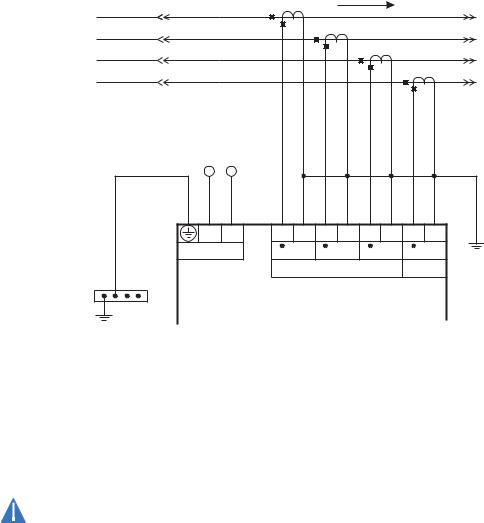
Input/Output modules
Phase current inputs (IO_A module)
Figure 11: Typical phase current input connections |
|
|
|
|
|
|||||
|
|
|
|
|
|
Power flow |
|
|
|
|
A |
|
|
|
|
|
|
|
|
|
|
B |
|
|
|
|
|
|
|
|
|
|
C |
|
|
|
|
|
|
|
|
|
|
N |
|
|
|
|
|
|
|
|
|
|
To switchgear |
|
|
|
|
|
|
|
|
|
|
ground bus |
– |
+ |
|
|
|
|
|
|
|
|
|
|
|
|
|
|
|
|
|
||
|
N |
L |
E1 |
E2 |
E3 |
E4 |
E5 |
E6 |
E7 |
E8 |
|
Control power |
CT1 |
CT2 |
CT3 |
G/F |
|||||
|
|
|
|
Phase current inputs |
|
|
||||
Automatic Transfer Control System
889744A1.CDR
The MX350 has three channels for phase current inputs, plus an additional channel input for ground/neutral current, each with an isolating transformer. The phase CTs should be chosen so the nominal current is not less than 50% of the rated phase CT primary. Ideally, the phase CT primary should be chosen such that the nominal current is 100% of the phase CT primary or slightly less, never more. This will ensure maximum accuracy for the current measurements. The maximum phase CT primary current is 4000 A.
The MX350 measures up to 1.5 times the phase current nominal rating. CTs with 1 A or 5 A secondaries must be used if the FLA is greater than 5 A. The chosen CTs must be capable of driving the MX350 phase CT burden.
Polarity of the phase CTs is critical for negative-sequence unbalance calculation, power measurement, and residual ground current detection (if used).
CAUTION
2–10 |
MX350 AUTOMATIC TRANSFER CONTROL SYSTEM – INSTRUCTION MANUAL |
CHAPTER 2: INSTALLATION |
ELECTRICAL INSTALLATION |
Phase voltage inputs (IO_B module)
The MX350 has three channels for AC voltage inputs. There are no internal fuses or ground connections on the voltage inputs. Polarity is critical for correct power measurement and voltage phase reversal operation.
Figure 12: Wye voltage connection
LOAD
|
N |
|
Typically |
A |
Typically |
|
||
|
|
|
generator |
B |
utility |
|
|
|
|
C |
|
– |
+ |
|
|
|
|
– |
+ |
|
|
|
|
N |
L |
D1 D2 |
D3 D4 |
D5 D6 |
D7 D8 |
N |
L |
C1 C2 |
C3 C4 |
C5 C6 |
C7 C8 |
Control power |
VT1 |
VT2 |
VT3 |
N/C |
Control power |
VT1 |
VT2 |
VT3 |
N/C |
||
|
|
Phase voltage inputs |
|
|
|
Phase voltage inputs |
|
||||
Auto Transfer Control |
|
|
|
Auto Transfer Control |
|
|
|
||||
889735A1.CDR
Figure 13: Delta voltage connection
|
|
|
|
|
|
|
|
LOAD |
|
|
|
|
|
|
From |
A |
|
|
|
|
|
|
|
|
|
|
|
|
From |
|
|
|
|
|
|
|
|
|
|
|
|
|
||
Source 2 |
B |
|
|
|
|
|
|
|
|
|
|
|
|
Source 1 |
(generator) C |
|
|
|
|
|
|
|
|
|
|
|
|
(utility) |
|
|
– |
+ |
|
|
|
|
|
– |
+ |
|
|
|
|
|
|
N |
L |
D1 D2 |
D3 D4 |
D5 D6 |
D7 |
D8 |
N |
L |
C1 C2 |
C3 C4 |
C5 C6 |
C7 |
C8 |
|
Control power |
VT1 |
VT2 |
VT3 |
N/C |
|
Control power |
VT1 |
VT2 |
VT3 |
N/C |
|
||
|
Phase voltage inputs |
|
|
|
|
|
Phase voltage inputs |
|
|
|
|
|
|
|
|
Auto Transfer Control |
|
|
|
|
Auto Transfer Control |
||
|
|
|
|
||||
|
|
|
|
||||
889736A1.CDR
MX350 AUTOMATIC TRANSFER CONTROL SYSTEM – INSTRUCTION MANUAL |
2–11 |
ELECTRICAL INSTALLATION
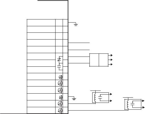
Type IO_K module connections
CHAPTER 2: INSTALLATION
The IO_K module handles the automatic delayed start of the engine in case there is a total power outage, i.e. Source 1 power fails and the MX350 is not powered by an auxiliary power source. The terminal assignments are as follows:
Terminal |
Type |
Function |
Type |
|
|
|
|
|
|
F1 |
Output |
S1 |
Sol Relay |
N.O. |
|
|
|
|
|
F2 |
Output |
S2 |
Sol Relay |
N.O. |
|
|
|
|
|
F3 |
N/A |
Common F1, F2 |
N/A |
|
|
|
|
|
|
F4 |
Output |
S1 |
Del Sol Relay |
N.O. |
|
|
|
|
|
F5 |
Output |
S2 |
Del Sol Relay |
N.O. |
|
|
|
|
|
F6 |
N/A |
Common F4, F5 |
N/A |
|
|
|
|
|
|
F7 |
Output |
Engine Start Signal (P Relay) |
N.O. |
|
|
|
|
|
|
F8 |
N/A |
Engine Start Signal, Common |
N/A |
|
|
|
|
|
|
F9 |
Output |
Engine Start Signal (P Relay) |
N.C. |
|
|
|
|
|
|
F10 |
Input |
SN Limit Switch |
pos. |
|
|
|
|
|
|
F11 |
Input |
SE Limit Switch |
pos. |
|
|
|
|
|
|
F12 |
Input |
SNO Limit Switch |
pos. |
|
|
|
|
|
|
F13 |
Input |
SEO Limit Switch |
pos. |
|
|
|
|
|
|
F14 |
N/A |
Input Common |
N/A |
|
|
|
|
|
|
Figure 14: IO_K module connections - standard ATS
Auto Transfer Control |
|
||
INPUT COMMON |
Inp |
~14 |
|
com |
0 VDC |
||
SOURCE 2 LIMIT SW |
Inp 4 |
~13 |
|
DELAYED INPUT |
|
||
|
|
|
|
SOURCE 1 LIMIT SW |
Inp 3 |
|
|
DELAYED INPUT |
~12 |
|
|
|
|
|
|
SOURCE 2 LIMIT SW |
Inp 2 |
~11 |
|
INPUT |
|
||
|
|
|
|
SOURCE 1 LIMIT SW |
Inp 1 |
~10 |
|
INPUT |
|
||
|
|
|
|
P. RELAY - ENGINE |
|
~9 |
|
START - N.C. |
|
|
|
|
|
|
|
P. RELAY - COMMON |
|
~8 |
|
P. RELAY - ENGINE |
|
~7 |
|
START - N.O. |
|
|
|
|
|
|
|
COIL CONTROL RELAYS SSR 3&4 |
~6 |
NC |
|
3 & 4 COMMON |
|
||
COM |
|
|
|
COIL CONTROL RELAY |
SSR |
~5 |
|
DEL (OPEN SRC 2) |
|
NC |
|
|
|
|
|
COIL CONTROL RELAY |
SSR |
|
|
DEL (OPEN SRC 1) |
|
~4 |
NC |
|
|
|
|
COIL CONTROL RELAYS SSR 1&2 |
|
|
|
1 & 2 COMMON |
|
~3 |
|
COM |
|
0 VDC |
|
|
|
||
COIL CONTROL RELAY |
SSR |
~2 |
|
SOURCE 2 |
|
|
|
|
|
|
|
COIL CONTROL RELAY |
SSR |
|
|
SOURCE 1 |
|
~1 |
|
|
|
|
|
SOURCE 2 LIMIT SWITCH (+24 V DC ACTIVE)
SOURCE 1 LIMIT SWITCH (+24 V DC ACTIVE)
A
STARTER
CCTRY GEN B
C
24 V DC
TO SOLENOID 24 V DC
TO SOLENOID
889741A1.CDR
2–12 |
MX350 AUTOMATIC TRANSFER CONTROL SYSTEM – INSTRUCTION MANUAL |
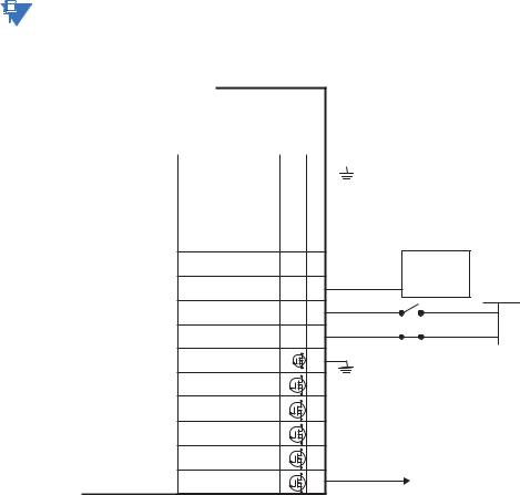
CHAPTER 2: INSTALLATION
Type IO_L module connections
NOTE
ELECTRICAL INSTALLATION
IO_L modules provide all user configurable I/O. Additionally, some of the I/O points on the first L module in slot G are used for some factory configured I/O. The terminal configuration is as follows:
Terminal |
Terminal |
Terminal |
Type |
Function |
|
|
|
|
|
G1 |
H1 |
J1 |
Output |
Output 1 |
|
|
|
|
|
G2 |
H2 |
J2 |
Output |
Output 2 |
|
|
|
|
|
G3 |
H3 |
J3 |
Output |
Output 3 |
|
|
|
|
|
G4 |
H4 |
J4 |
Output |
Output 4 |
|
|
|
|
|
G5 |
H5 |
J5 |
Output |
Output 5 |
|
|
|
|
|
G6 |
H6 |
J6 |
Common |
Common, Ouputs 1 to 5 |
|
|
|
|
|
G7 |
H7 |
J7 |
Input |
Input 1 |
|
|
|
|
|
G8 |
H8 |
J8 |
Input |
Input 2 |
|
|
|
|
|
G9 |
H9 |
J9 |
Input |
Input 3 |
|
|
|
|
|
G10 |
H10 |
J10 |
Input |
Input 4 |
|
|
|
|
|
G11 |
H11 |
J11 |
Input |
Input 5 |
|
|
|
|
|
G12 |
H12 |
J12 |
Input |
Input 6 |
|
|
|
|
|
G13 |
H13 |
J13 |
Input |
Input 7 |
|
|
|
|
|
G14 |
H14 |
J14 |
Common |
Common, Inputs 1 to 7 |
|
|
|
|
|
Terminals G7 and G8 are always used as DS and Q2, respectively. Depending on the type of switch and the features ordered, Terminals G1 through G5 as well as G9 through G13 may not be available for customer configuration.
Figure 15: IO_L module - standard ATS
Auto Transfer Control |
||||
|
|
|
|
|
|
Inp |
|||
USER DEFINED |
com ~14 |
|
0 VDC |
|
|
|
|||
USER DEFINED |
Inp 7 ~13 |
|||
|
|
|
|
|
USER DEFINED |
Inp 6 ~12 |
|||
|
|
|
|
|
USER DEFINED |
Inp 5 ~11 |
|||
USER DEFINED |
Inp 4 |
~10 |
LOAD SHED |
|
HARDWARE |
||||
|
|
|
||
LOAD SHED FROM S2 |
Inp 3 ~9 |
FOR LOCAL |
||
OPTION |
||||
|
|
|
||
|
|
|
24 V DC |
|
TEST WITH LOAD |
Inp 2 |
~8 |
|
|
|
|
|
NO |
|
DISCONNECT SW |
Inp 1 |
~7 |
|
|
|
|
|
NC |
|
|
SSR |
|
|
|
USER DEFINED |
|
~6 |
|
|
COM |
|
0 VDC |
SSR5 |
|
|
USER DEFINED |
~5 |
|
SSR4 |
|
|
USER DEFINED |
~4 |
|
SSR3 |
|
|
USER DEFINED |
~3 |
|
SSR2 |
|
|
USER DEFINED |
~2 |
|
SSR1 |
|
|
LOAD SHED FROM S2 |
~1 |
TO BREAKER |
889742A1.CDR
MX350 AUTOMATIC TRANSFER CONTROL SYSTEM – INSTRUCTION MANUAL |
2–13 |
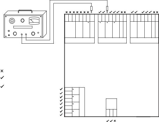
ELECTRICAL INSTALLATION |
CHAPTER 2: INSTALLATION |
Dielectric strength testing |
|
|
|
|
|
|
|
|
|
|
|
|
|
|
|
|||
Figure 16: Testing for dielectric strength |
|
|
|
|
|
|
|
|
|
|
|
|
|
|||||
|
|
|
|
|
|
|
|
|
* |
* |
* |
* * |
|
* |
* |
* |
* * |
|
VOLTAGE ADJUST |
HV ON |
|
+ |
– |
C + – |
R |
I |
SG |
C1 C2 |
C3 C4 |
C5 C6 C7 |
C8 |
D1 D2 D3 D4 D5 D6 D7 |
D8 |
||||
|
|
|
|
|
|
|
|
|
|
|
||||||||
|
|
kV |
|
RS485 |
Thermistor |
Core balance |
GroundSurge |
|
|
|
|
GroundSurge |
|
|
|
|
GroundSurge |
|
DIELECTRIC STRENGTH TESTER |
|
|
VT1 |
VT2 |
VT3 |
|
VT1 |
VT2 |
VT3 |
|||||||||
LINE FAULT |
|
|
|
|
|
|
|
|
|
|
|
|
|
|
|
|
|
|
POWER |
|
FAULT |
RESET |
|
|
|
|
|
|
|
|
|
|
|
|
|
|
|
|
BLACK |
RED |
|
|
|
|
|
|
|
|
|
|
|
|
|
|
|
|
ON |
|
|
|
|
|
|
|
|
|
|
|
|
|
|
|
|
|
|
|
|
|
|
CPU module |
|
|
|
|
VT1 module |
|
|
|
VT2 module |
|
||||
|
|
Automatic Transfer Control System |
||
|
Do not HI-POT test |
|
|
|
|
HI-POT test at 1.9 kV AC for 1 second, or |
|
|
|
* |
1.6 kV AC for 1 minute (per UL 508) |
|
|
|
Remove surge ground during test |
|
|
|
|
|
D1 |
CT1 |
|
|
|
D2 |
CT |
|
|
|
D3 |
CT2 |
|
|
|
D4 |
Module |
Power |
|
|
D5 |
|
||
|
CT3 |
|
supply |
|
|
D6 |
|
|
|
|
D7 |
CT4 |
|
L N G |
|
D8 |
|
|
|
889738A1.CDR
It may be required to test for dielectric strength (“flash” or “HI-POT”) with the MX350 installed. The MX350 is rated for 1.9 kV AC for 1 second, or 1.6 kV AC for 1 minute (per UL 508) isolation between relay contacts, CT inputs, VT inputs and the surge ground terminal SG. Some precautions are required to prevent damage to the MX350during these tests.
Filter networks and transient protection clamps are used between VT input and the surge ground terminal. This is intended to filter out high voltage transients, radio frequency interference (RFI), and electromagnetic interference (EMI). The filter capacitors and transient suppressors may be damaged by continuous high voltage. Disconnect the surge ground terminals (C8 and D8) during testing of VT inputs. The CT inputs, control power, and output relays do not require any special precautions. Low voltage inputs (less than
30 volts), and RS485 communication ports are not to be tested for dielectric strength under any circumstance (see above).
2–14 |
MX350 AUTOMATIC TRANSFER CONTROL SYSTEM – INSTRUCTION MANUAL |
Loading...