


Instruction Manual |
657 Actuator (30-70 and 87) |
D100306X012 |
November 2013 |
|
|
Fisherr 657 Diaphragm Actuator
Sizes 30-70 and 87
Contents
Introduction . . . . . . . . . . . . . . . . . . . . . . . . . . . . . . . . . 1 Scope of Manual . . . . . . . . . . . . . . . . . . . . . . . . . . . . . 1 Description . . . . . . . . . . . . . . . . . . . . . . . . . . . . . . . . . 2 Specifications . . . . . . . . . . . . . . . . . . . . . . . . . . . . . . . 2 Educational Services . . . . . . . . . . . . . . . . . . . . . . . . . 3
Installation . . . . . . . . . . . . . . . . . . . . . . . . . . . . . . . . . . 3 Mounting the Actuator on the Valve . . . . . . . . . . . . 4 Discussion of Bench Set . . . . . . . . . . . . . . . . . . . . . . . 5 Spring Verification . . . . . . . . . . . . . . . . . . . . . . . . . . . 6 Installing the Stem Connector Assembly . . . . . . . . . 7 Friction Discussion . . . . . . . . . . . . . . . . . . . . . . . . . . . 8 Deadband Measurement . . . . . . . . . . . . . . . . . . . . . . 9 Loading Connection . . . . . . . . . . . . . . . . . . . . . . . . . 10
Maintenance . . . . . . . . . . . . . . . . . . . . . . . . . . . . . . . . 11 Actuator Maintenance . . . . . . . . . . . . . . . . . . . . . . . 11 Top-Mounted Handwheel Assembly . . . . . . . . . . . 13 Side-Mounted Handwheel for Sizes 34
through 60 Actuators . . . . . . . . . . . . . . . . . . . . . 15 Side-Mounted Handwheel for Sizes 70
and 87 Actuators . . . . . . . . . . . . . . . . . . . . . . . . . 16 Casing-Mounted Adjustable Travel Stops . . . . . . . 18 Parts Ordering . . . . . . . . . . . . . . . . . . . . . . . . . . . . . . . 20 Parts Kits . . . . . . . . . . . . . . . . . . . . . . . . . . . . . . . . . . . 20 Kits for Side-Mounted Handwheels . . . . . . . . . . . . 20 Kits for Top-Mounted Handwheels . . . . . . . . . . . . . 20 Parts List . . . . . . . . . . . . . . . . . . . . . . . . . . . . . . . . . . . 21 Actuator Assembly (figures 6, 7, or 8) . . . . . . . . . . 21
Figure 1. Fisher 657 or 657-4 Actuator Mounted on an easy-e™ Valve
W2174-2
Top-Mounted Handwheel (figures 9 or 10) . . . . . . 21 Side-Mounted Handwheel (figure 11 or 13) . . . . . 24 Casing-Mounted Adjustable Up Travel Stops
(figures 14 or 15) . . . . . . . . . . . . . . . . . . . . . . . . . 29 Casing-Mounted Adjustable Down Travel Stops
(figure 16) . . . . . . . . . . . . . . . . . . . . . . . . . . . . . . 30
Introduction
Scope of Manual
This instruction manual provides information on installation, adjustment, maintenance, and parts ordering for the Fisher 657 actuator in sizes 30 through 70 and size 87. The 657-4 actuator in sizes 70 and 87 is also covered. Refer to separate instruction manuals for information about the valve positioner and other accessories used with these actuators.
Do not install, operate, or maintain a 657 actuator without being fully trained and qualified in valve, actuator, and accessory installation, operation, and maintenance. To avoid personal injury or property damage, it is important to carefully read, understand, and follow all the contents of this manual, including all safety cautions and warnings. If you have any questions about these instructions, contact your Emerson Process Management sales office before proceeding.
www.Fisher.com

657 Actuator (30-70 and 87) |
|
|
|
|
|
|
|
|
|
Instruction Manual |
|
|||||
November 2013 |
|
|
|
|
|
|
|
|
|
|
|
D100306X012 |
|
|||
|
|
|
|
|
|
|
|
|
|
|
|
|
|
|
|
|
Table 1. Specifications |
|
|
|
|
|
|
|
|
|
|
|
|
|
|
|
|
|
|
|
|
|
|
|
|
ACTUATOR SIZE |
|
|
|
|
|
|
||
SPECIFICATION(1) |
|
|
|
|
|
|
|
|
|
|
|
|
||||
|
|
|
|
|
|
|
|
|
|
|
|
|
|
|
||
|
30 |
|
34 |
40 |
45 |
|
46 |
|
50 |
60 |
70(1) |
|
87(1) |
|
||
|
|
|
|
|
|
|
|
|||||||||
Nominal Effective Area |
|
cm2 |
297 |
|
445 |
445 |
677 |
|
1006 |
|
677 |
1006 |
1419 |
|
1419 |
|
|
Inch2 |
46 |
|
69 |
69 |
105 |
|
156 |
|
105 |
156 |
220 |
|
220 |
|
|
|
|
|
|
|
|
|
||||||||||
Yoke Boss Diameters |
|
mm |
54 |
|
54 |
71 |
71 |
|
71 |
|
90 |
90 |
90 |
|
127 |
|
|
|
|
|
|
|
|
|
|
|
|
|
|
|
|
|
|
|
Inches |
2-1/8 |
|
2-1/8 |
2-13/16 |
2-13/16 |
|
2-13/16 |
|
3-9/16 |
3-9/16 |
3-9/16 |
|
5 |
|
|
|
|
|
|
|
|
|
||||||||||
|
|
|
|
|
|
|
|
|
|
|
|
|
|
|
|
|
Acceptable Valve |
|
mm |
9.5 |
|
9.5 |
12.7 |
12.7 |
|
12.7 |
|
19.1 |
19.1 |
19.1 |
|
25.4 |
|
Stem Diameters |
|
Inches |
3/8 |
|
3/8 |
1/2 |
1/2 |
|
1/2 |
|
3/4 |
3/4 |
3/4 |
|
1 |
|
|
|
|
|
|
|
|
|
|
|
|
|
|
|
|
|
|
Maximum Allowable |
|
N |
10230 |
|
10230 |
12010 |
25131 |
|
33582 |
|
25131 |
30246 |
39142 |
|
39142 |
|
Output Thrust(4) |
|
Lb |
2300 |
|
2300 |
2700 |
5650 |
|
7550 |
|
5650 |
6800 |
8800 |
|
8800 |
|
Maximum Travel(2) |
|
mm |
19 |
|
29 |
38 |
51 |
|
51 |
|
51 |
51 |
76(3) |
|
76(3) |
|
|
Inches |
0.75 |
|
1.125 |
1.5 |
2 |
|
2 |
|
2 |
2 |
3(3) |
|
3(3) |
|
|
|
|
|
|
|
|
|
||||||||||
Maximum Casing |
|
Bar |
8.6 |
|
4.5 |
4.5 |
3.4 |
|
2.8 |
|
3.4 |
2.8 |
3.8 |
|
3.8 |
|
Pressure for |
|
|
|
|
|
|
|
|
|
|
|
|
|
|
|
|
|
Psig |
125 |
|
65 |
65 |
50 |
|
40 |
|
50 |
40 |
55 |
|
55 |
|
|
Actuator Sizing(4) |
|
|
|
|
|
|
||||||||||
Maximum Diaphragm |
|
Bar |
9.6 |
|
5.2 |
5.2 |
4.1 |
|
3.4 |
|
4.1 |
3.4 |
4.5 |
|
4.5 |
|
Casing Pressure(4)(5) |
|
Psig |
140 |
|
75 |
75 |
60 |
|
50 |
|
60 |
50 |
65 |
|
65 |
|
Material Temperature |
|
_C |
|
Nitrile Elastomers: -40 to 82_C, Silicone Elastomers: -54 to 149_C, Fluorocarbons: -18 to 149_C |
|
|
||||||||||
Capabilities |
|
_F |
|
Nitrile Elastomers: -40 to 180_F, Silicone Elastomers: -65 to 300_F, Fluorocarbons: 0 to 300_F |
|
|
||||||||||
|
|
|
|
|
|
|
|
|
|
|
|
|
|
|
|
|
Pressure Connections |
|
1/4 NPT |
X |
|
X |
X |
X |
|
X |
|
X |
X |
- - - |
|
- - - |
|
(internal) |
|
1/2 NPT |
- - - |
|
- - - |
- - - |
- - - |
|
- - - |
|
- - - |
- - - |
X |
|
X |
|
|
|
|
|
|
|
|
|
|
|
|
|
|
|
|
|
|
Approximate Weights |
|
kg |
16 |
|
22 |
23 |
37 |
|
49 |
|
42 |
53 |
107 |
|
116 |
|
|
|
|
|
|
|
|
|
|
|
|
|
|
|
|
|
|
|
Lb |
36 |
|
48 |
51 |
82 |
|
107 |
|
92 |
116 |
235 |
|
255 |
|
|
|
|
|
|
|
|
|
||||||||||
|
|
|
|
|
|
|
|
|
|
|
|
|
|
|
|
|
1.These values also apply to the 657-4 actuator construction.
2.Actuator travel may be less than the value listed after connecting the actuator to the valve.
3.Maximum travel for 657-4 is 102 mm (4 inches).
4.Normal operating diaphragm pressure must not exceed maximum diaphragm casing pressure and must not produce a force on the actuator stem greater than the maximum allowable out put thrust or the maximum allowable valve stem load. Contact your Emerson Process Management sales office with questions concerning maximum allowable valve stem load.
5.This maximum casing pressure is not to be used for normal operating pressure. Its purpose is to allow for typical regulator supply settings and/or relief valve tolerances.
Description
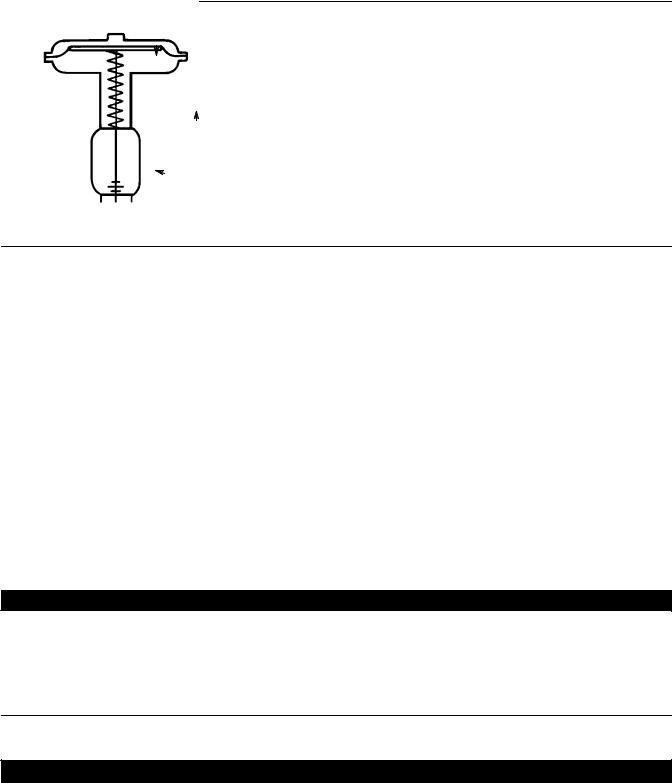
The 657 actuator (figure 1) and the 657-4 actuator are direct-acting, spring-opposed diaphragm actuators. They provide automatic operation of control valve body assemblies. The 657 actuator offers 76 mm (3 inches) maximum actuator travel. The 657-4 actuator provides 102 mm (4 inches) maximum actuator travel. Both actuators position the valve plug in response to varying pneumatic loading pressure on the actuator diaphragm. Figure 2 shows the operation of these actuators.
A 657 or 657-4 actuator can be equipped with either a top-mounted or a side-mounted handwheel assembly. A top-mounted handwheel assembly is used as an adjustable up travel stop to limit actuator travel in the up direction (see figure 2). A side-mounted handwheel assembly is usually used as an auxiliary manual actuator. Adjustable casing-mounted up or down travel stops are also available for this actuator.
Note
If repeated or daily manual operation is expected, the actuator should be equipped with a side-mounted handwheel rather than a casing-mounted travel stop or top-mounted handwheel.
The side-mounted handwheel is designed for more frequent use as a manual operator.
Specifications
Refer to table 1 for Specifications of the 657 and 657-4 actuators. See the actuator nameplate for specific information about your actuator.
2
Instruction Manual |
657 Actuator (30-70 and 87) |
D100306X012 |
November 2013 |
|
|
Figure 2. Schematic of Fisher 657 and 657-4 Actuators
AIR PUSHES
STEM DOWN
SPRING LIFTS
STEM UP
 STEM
STEM
AF3833-A
A0792-2
Educational Services
For information on available courses for Fisher 657 diaphragm actuators, as well as a variety of other products, contact:
Emerson Process Management Educational Services, Registration P.O. Box 190; 301 S. 1st Ave. Marshalltown, IA 50158-2823 Phone: 800-338-8158 or
Phone: 641-754-3771
FAX: 641-754-3431
e-mail: education@emerson.com
Installation
Key number locations are shown in figures 6, 7, and 8, unless otherwise indicated. Also, refer to figure 3 for location of parts.

 WARNING
Always wear protective gloves, clothing, and eyewear when performing any installation operations to avoid personal injury.
Check with your process or safety engineer for any additional measures that must be taken to protect against process media.
If installing into an existing application, also refer to the WARNING at the beginning of the Maintenance section in this instruction manual.
CAUTION
To avoid parts damage, do not use an operating pressure that exceeds the Maximum Diaphragm Casing Pressure (table 1) or produces a force on the actuator stem greater than the Maximum Allowable Output Thrust (table 1) or the maximum
3

657 Actuator (30-70 and 87) |
Instruction Manual |
November 2013 |
D100306X012 |
|
|
allowable valve stem load. (Contact your Emerson Process Management sales office with questions concerning maximum allowable valve stem load.)
DValve/Actuator Assembly: If the actuator and valve are shipped together as a control valve assembly, it has been adjusted at the factory, and may be installed in the pipeline. After installing the valve in the pipeline, refer to the Loading Connection procedures.
DActuator Mounting: If the actuator is shipped separately or the actuator has been removed from the valve, it is necessary to mount the actuator on the valve before placing the valve in the pipeline. Refer to the actuator mounting procedures before placing the valve in service. You may perform the Bench Set Spring Adjustment procedures in this section to confirm that the adjustment has not changed since it was shipped from the factory.
DPositioner: If a positioner is installed, or is to be installed on the actuator, refer to the positioner instruction manual for installation. During the adjustment procedures, it will be necessary to provide a temporary loading pressure to the actuator diaphragm.
Mounting the Actuator on the Valve
The 657 actuator spring loading pushes the actuator stem up towards the actuator diaphragm (see figure 2). This spring action moves the stem away from the valve while installing the actuator.
CAUTION
If the valve stem is allowed to remain in the up position (towards the actuator) during mounting, it can interfere with the actuator mounting, possibly damage valve stem threads or bend the valve stem. Be sure the valve stem is pushed down (into the valve body), away from the actuator while mounting.
Provide a temporary method of applying diaphragm loading pressure to the diaphragm to extend the actuator stem during bench set spring adjustments.
1.Provide a vise or some other method of supporting the valve and the weight of the actuator during assembly. For direct or reverse acting valves, push the valve stem down away from the actuator while mounting the actuator.
2.Screw the stem locknuts all the way onto the valve stem. With the concave side of the travel indicator disk (key 14) facing the valve, install the travel indicator disk on the valve stem. (Note: The travel indicator disk is not used with size 87 actuators.)
3.Lift or hoist the actuator onto the valve bonnet:
a.For size 87 actuators, insert the cap screws and tighten the hex nuts, securing the actuator to the bonnet.
b.For all other size actuators, screw the yoke locknut onto the valve bonnet and tighten the locknut. (Note: On small size actuators, it may be necessary to remove the indicator disk and re-install it while lowering the actuator on to the valve because the disk will not go through the actuator yoke opening.)
4.Do not connect the actuator stem to the valve stem at this time. Whenever the actuator is installed on the valve, it is recommended to perform the Bench Set Spring Adjustment procedure to verify that the actuator is still adjusted correctly.
4
Instruction Manual |
657 Actuator (30-70 and 87) |
D100306X012 |
November 2013 |
|
|
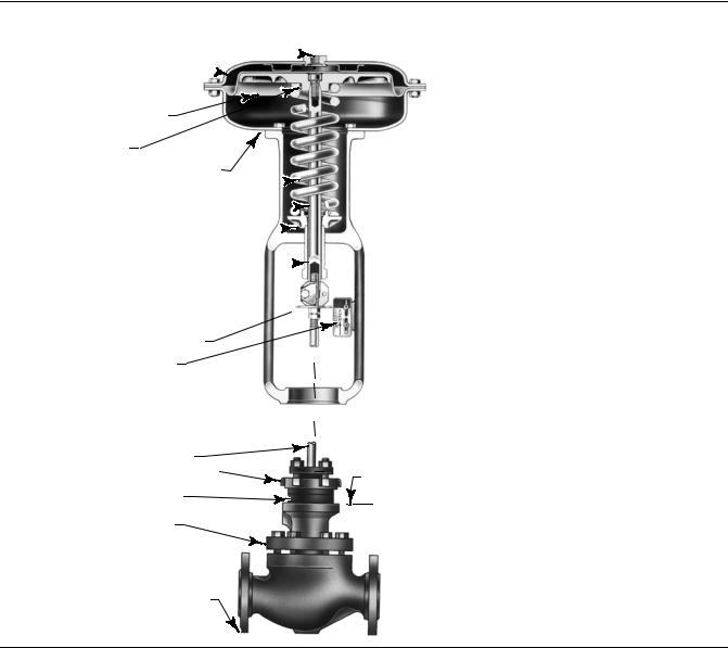
Figure 3. Actuator Mounting Components for Size 30 through 70 Actuators
NPT INTERNAL CONNECTION 
DIAPHRAGM CASING 

DIAPHRAGM AND STEM
SHOWN IN UP POSITION
DIAPHRAGM PLATE
LOWER DIAPHRAGM CASING
ACTUATOR SPRING 
ACTUATOR STEM 
SPRING SEAT 
SPRING ADJUSTOR 
STEM CONNECTOR 
YOKE 

TRAVEL INDICATOR DISK
INDICATOR SCALE
W0363-1
VALVE STEM |
MATCH LINE |
|
YOKE LOCK NUT |
||
FOR ACTUATOR |
||
|
||
YOKE BOSS DIAMETER |
|
|
BONNET |
|
TYPICAL VALVE
(REFER TO VALVE MANUAL)
W6199-1
Discussion of Bench Set
The bench set pressure values are used to adjust the initial compression of the actuator spring with the valve-actuator assembly “on the bench.” The correct initial compression is important for the proper functioning of the valve-actuator assembly when it is put into service and the proper actuator diaphragm operating pressure is applied.
The bench set values are established with the assumption that there is no packing friction. When attempting to adjust the spring in the field, it is very difficult to ensure that there is no friction being applied by “loose” packing.
Accurate adjustment to the bench set range can be made during the actuator mounting process by making the adjustment before the actuator is connected to the valve (see the Spring Verification procedure).
5

657 Actuator (30-70 and 87) |
Instruction Manual |
November 2013 |
D100306X012 |
|
|
Figure 4. Bench Set Adjustment
SPRING ADJUSTER |
RATED VALVE |
|
|
|
|
LOWER BENCH SET |
TRAVEL MEASURE |
|
LOADING PRESSURE |
|
|
1 |
|
|
UPPER BENCH SET |
|
|
|
|||||
PRESSURE MARK |
|
|
|
|
|
|||
3 |
4 |
|
|
|||||
|
|
|
|
|
|
|
|
|
|
|
|
|
|
|
MARK |
||
|
|
|
VALVE |
VALVE |
|
|
||
|
|
|
3 |
|||||
|
|
|
STEM |
STEM HERE |
||||
NOTES: |
THE LOWER PSIG LOADING PRESSURE (MARKED ON NAMEPLATE) WHERE THE FIRST MOVEMENT OF |
|||||||
1 |
|
|
||||||
|
ACTUATOR STEM IS DETECTED. |
|
|
|
||||
2 |
|
|
THE UPPER PSIG LOADING PRESSURE EXTENDS ACTUATOR STEM. |
|||||
|
|
|
MARK THIS POINT WITH TAPE OR A MARKER. |
|
|
|
||
3 |
|
|
|
|
|
|||
4 |
|
|
MEASURE DISTANCE OF TRAVEL. IT SHOULD EQUAL THE TRAVEL SPAN SHOWN ON THE NAMEPLATE. |
|||||
40A8715-B |
|
|
|
|
|
|
||
B2426 |
|
|
|
|
|
|
||
ACTUATOR STEM
 2 UPPER BENCH SET LOADING PRESSURE
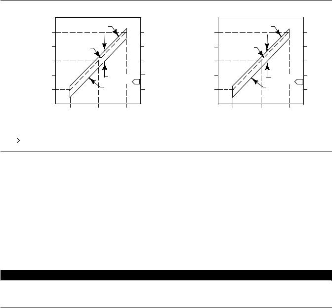
Spring Verification
Ensure that the actuator stem is at the top of its travel as shown in figure 4 and not connected to the valve. (Note: Some spring compression is required to move the diaphragm to the top of its travel.) The steps provided are the same for push-down-to-close (direct acting) or push-down-to-open (reverse acting) valves.

 WARNING
When moving the actuator stem with diaphragm loading pressure, use caution to keep hands and tools out of the actuator stem travel path. Personal injury and/or property damage is possible if something is caught between the actuator stem and other control valve assembly parts.
Also, provide a certified pressure gauge suitable to accurately read the diaphragm pressure from 0 through 0.3 bar (5 psig) above the upper operating range pressure marked on the nameplate. Apply loading pressure to the diaphragm.
CAUTION
Stroke the actuator a few times to ensure that the pressure gauge is working correctly, and that the actuator is functioning properly. To prevent actuator damage, it is important to ensure that the actuator stem is stroking smoothly and not exhibiting binding or excessive friction. Binding or excessive friction could be an indicator of incorrect assembly or damaged parts.
6

Instruction Manual |
657 Actuator (30-70 and 87) |
D100306X012 |
November 2013 |
|
|
1.If not already accomplished, provide a temporary means of applying an adjustable loading pressure to the actuator during bench set adjustments.
2.Set the diaphragm loading pressure at 0 bar (0 psig). Then, slowly raise the pressure towards the lower bench set pressure, as indicated on the nameplate, while checking for the first linear movement of the actuator stem. The actuator stem should show movement at the lower bench set pressure. If movement occurs before or after the lower pressure is reached, adjust the spring adjuster (see figure 4) into or out of the yoke until the actuator stem's movement is first detected at the lower bench set pressure.
Note
Before turning the spring adjuster on size 70 or 87 actuators, assemble the stem connector around the actuator stem and the anti-rotating lug on the yoke. Mark the actuator stem as a visual reference to verify that stem rotation does not occur. Remove the stem connector before rechecking the bench set.
3.Be sure the spring adjuster is adjusted to meet the requirements of step 2 above.
4.Apply the upper bench set pressure, as indicated on the nameplate. This pressure extends the actuator stem down towards the valve. (Note: The actuator stem may slide over the valve stem as shown in figure 4.) At the end of the actuator stem, use a marker or a piece of tape to mark the valve stem (see figure 4). (Note: If the actuator stem does not pass over the valve stem, provide a method to mark this point of stem travel.)
5.Slowly decrease the diaphragm loading pressure to the lower bench set pressure, as indicated on the nameplate.
6.Measure the distance between the marker or tape on the valve stem to the end of the actuator stem. The distance should match the rated travel indicated on the nameplate.
7.If the measured travel matches the nameplate travel, bench set is complete. Proceed to the Installing the Stem Connector Assembly subsection.
8.If the measured travel is not exact, consider the spring free-length and spring rate tolerances may produce a slightly different bench set than specified. Contact your Emerson Process Management sales office for assistance.
Installing the Stem Connector Assembly
When installing the stem connector assembly (key 26), the actuator and valve stem threads should engage the threads of the stem connector by the distance equal to the diameter of the stem.

 WARNING
Install the stem connector securely before a positioner is mounted to the actuator and pressurized, using only a regulator-controlled air supply, not the positioner, to move the actuator stem.
To avoid personal injury or property damage, keep hands and tools out of the actuator stem travel path while applying loading pressure to move the actuator stem in the following steps.
CAUTION
To avoid damaging the seating surfaces, do not rotate the valve plug while it is seated. Exercise care while installing the stem connector assembly to avoid damage to the valve plug stem and valve stem threads.
7

657 Actuator (30-70 and 87) |
Instruction Manual |
November 2013 |
D100306X012 |
|
|
Note
Replacement stem connectors are an assembly of two stem connector halves, cap screws, and a spacer between the connector halves. Remove the spacer and discard, if present, before clamping the actuator and valve stems together. Use only a mated pair of stem connector halves.
1.If necessary, push the valve stem down so that it is touching the seat ring on direct acting valves. For reverse acting valves, push the stem down to the open position.
If necessary, screw the valve stem locknuts down, away from the connector location. For all actuators except size 87, ensure that the travel indicator disk (key 14) is located on top of the locknuts.
2.Slowly increase the diaphragm pressure to the upper bench set pressure. This should be the same pressure used in the Spring Verification steps, and it is marked on the nameplate.
3.Place the stem connector half with the threaded holes, approximately half way between the actuator and valve stems, and align with the stem connector. A slight change to loading pressure may be necessary to align the threads. Refer to figures 6, 7, and 8 to help locate the connector position.
CAUTION
Incomplete engagement of either the valve stem or actuator stem in the stem connector can result in stripped threads or improper operation. Be sure that the length of each stem clamped in the stem connector is equal to or greater than one diameter of that stem. Damage to threads on either stem or in the stem connector can cause the parts to be replaced prematurely. Do not loosen the cap screws when the stem connector has spring or loading pressure force applied.
4.Install the other half of the stem connector and insert the cap screws and tighten them while ensuring even spacing between the stem connector halves on all sides. If installing a positioner, also attach the feedback bracket at the same time.
CAUTION
Over-tightening the valve stem locknuts can make disassembly difficult.
5.Screw the valve stem locknuts up against the stem connector for the size 87 actuator. For all other actuator sizes, screw the valve stem locknuts up until the indicator disk contacts the bottom of the stem connector. Do not overtighten the locknuts.
6.Slowly stroke the valve from fully open to fully closed and verify full rated travel is achieved.
Be sure that the valve is in the closed position. Loosen the screws on the travel indicator scale (key 18), and align it with the travel indicator disk (key 14) or stem connector for the size 87 actuator. Stroke the valve full travel to ensure that the travel matches the rated travel on the nameplate. If valve travel is not correct, repeat the stem connector procedure.
Friction Discussion
If you are attempting to adjust the bench set after the actuator is connected to the valve and the packing tightened, you must take friction into account. Make the spring adjustment so full actuator travel occurs at the bench set values
8
Instruction Manual |
657 Actuator (30-70 and 87) |
D100306X012 |
November 2013 |
|
|
(a) plus the friction force divided by the effective diaphragm area with increasing diaphragm pressure or (b) minus the friction force divided by the effective diaphragm area with decreasing diaphragm pressure.
If the stem connector assembly has been installed, the valve friction may be determined by the following procedure: 1. Install a pressure gauge in the actuator loading pressure line that connects to the actuator diaphragm casing.
Note
Steps 2 and 4 require that you read and record the pressure shown on the pressure gauge.
2.Increase the actuator diaphragm pressure and read the diaphragm pressure as the actuator reaches a travel position in the rated travel of the valve that does not contact a travel stop. Make a reference mark on the travel indicator scale using tape or some other method at this point.
3.Increase the actuator diaphragm pressure until the actuator is at a travel position greater than the position referenced in step 2 using the reference point to identify first movement.
4.Decrease the actuator diaphragm pressure and read the diaphragm pressure as the actuator returns to the position referenced in step 2.
The difference between the two diaphragm pressure readings is the change in the diaphragm pressure required to overcome the friction forces in the two directions of travel.
5. Calculate the actual friction force:
Friction |
Difference |
|
Effective |
Force, = 0.5 |
in pressure |
¢ |
diaphragm area, |
pounds |
readings, psig |
|
inches2 |
Refer to table 1 for the effective diaphragm area.
It is difficult to rotate the spring adjustor (key 74, figures 6, 7, and 8) when the full actuator loading pressure is applied to the actuator. Release the actuator loading pressure before adjusting. Then re-apply loading pressure to check the adjustment.
Note
For push-down-to-close valves, the valve plug seat is the limit for downward travel and the actuator up-stop is the limit for upward (away from the valve) movement. For push-down-to-open valves, the actuator down stop is the limit for downward movement, and the valve seat is the limit for upward (away from the valve) movement.
Deadband Measurement
Deadband is caused by packing friction, unbalanced forces, and other factors in the control valve assembly. Deadband is the range a measured signal can vary without initiating a response from the actuator (see figure 5). Each actuator spring has a fixed spring rate (force divided by compression). You have verified that the right spring was installed in the actuator by completing the Spring Verification steps.
Deadband is one factor that affects the control valve assembly operation during automatic loop control. The control loop tolerance for deadband varies widely depending on the loop response. Some common symptoms of the
9
657 Actuator (30-70 and 87) |
Instruction Manual |
November 2013 |
D100306X012 |
|
|
deadband being too wide are no movement, a “jump” movement, or oscillating movements of the actuator during automatic loop control. The following steps are provided to determine the span of deadband. The percent of deadband is helpful in troubleshooting problems with the process control loop.
1.Start at a pressure near the lower bench set pressure, slowly increase pressure until the valve is approximately at mid-travel. Note this pressure reading.
2.Slowly decrease pressure until movement of the valve stem is detected, and note this pressure.
3.The difference between these two pressures is deadband, in psi.
4.Calculate the percent of deadband by:
Deadband, psi
Deadband = –––––––––––––– = nn%
Bench Set Span, psi
Figure 5. Typical Valve Response to Deadband
|
|
|
CLOSING |
|
|
||
PSIG |
UPPER |
|
VALVE |
|
1.0 |
BAR |
|
BENCH SET 15 |
|
|
|||||
PRESSURE |
|
|
|
|
|||
PRESSURE, |
|
|
|
|
PRESSURE, |
||
|
BENCH SET |
|
|
||||
|
9 |
|
|
0.6 |
|||
DIAPHRAGM |
|
|
|
RANGE OF |
|
DIAPHRAGM |
|
LOWER |
|
|
DEADBAND |
1 |
|||
3 |
OPENING |
0.2 |
|||||
|
BENCH SET |
|
|||||
|
VALVE |
|
|||||
|
PRESSURE |
|
|
|
|
|
|
|
|
0 |
|
|
|
|
|
|
|
OPEN |
MID RANGE |
CLOSED |
|
||
VALVE TRAVEL
|
|
DIRECT ACTING VALVE |
NOTE: |
DEADBAND IS CAUSED BY FRICTION. |
|
1 |
|
|
A6763-2 |
|
|
|
|
|
OPENING |
|
|
||
PSIG |
UPPER |
|
VALVE |
|
1.0 |
BAR |
|
BENCH SET 15 |
|
|
|||||
PRESSURE |
|
|
|
|
|||
PRESSURE, |
|
|
|
|
PRESSURE, |
||
|
BENCH SET |
|
|
||||
|
9 |
|
|
0.6 |
|||
DIAPHRAGM |
|
|
|
RANGE OF |
|
DIAPHRAGM |
|
LOWER |
|
|
DEADBAND |
1 |
|||
3 |
CLOSING |
0.2 |
|||||
|
BENCH SET |
|
|||||
|
VALVE |
|
|||||
|
PRESSURE |
|
|
|
|
|
|
|
|
0 |
|
|
|
|
|
|
|
CLOSED |
MID RANGE |
OPEN |
|
|
|
VALVE TRAVEL
REVERSE ACTING VALVE
Loading Connection
The loading pressure connections are made at the factory if the valve, actuator, and positioner come as a unit. Keep the length of tubing or piping as short as possible to avoid transmission lag in the control signal. If a volume booster, valve positioner or other accessory is used, be sure that it is properly connected to the actuator. Refer to the positioner instruction manual or other manuals as necessary.
For actuators shipped separately or whenever the actuator pressure connections are installed, use the following steps:
1.Connect the loading pressure piping to the NPT internal connection in the top of the diaphragm casing.
2.For sizes 70 and 87 actuators, if necessary, remove the 1/4 NPT bushing if a 1/2 NPT internal connection is needed to increase connection size. The connection can be made with either piping or tubing.
3.Cycle the actuator several times to be sure that the valve stem travel is correct when the correct pressure ranges are applied to the diaphragm.

 WARNING
If valve stem travel appears to be incorrect, refer to the Bench Set Spring Adjustment procedures at the beginning of this section. To avoid personal injury or product damage, do not place the valve into service if it is not reacting correctly to diaphragm loading pressure changes.
10
 Loading...