


377 Trip Valve |
Product Bulletin |
62.3:377 |
|
D200318X012 |
July 2014 |
|
|
Fisherr 377 Trip Valve
Fisher 377 pressure sensing trip valves are for control applications where a specific valve/actuator action is required when supply pressure falls below a specific point. When supply pressure falls below the trip point (see figure 1), the trip valve causes the actuator to fail up, lock in the last position, or fail down. When the supply pressure rises above the trip point, the 377 trip valve automatically resets, allowing the system to return to normal operation. The trip valve can be top mounted on a manifold, yoke mounted, or bracket mounted to match the application requirements. 377 trip valves can be used with Fisher 480, 585C, 685, 1061, 1066, 1069, and Bettist G Series piston actuators.
W4292 1
Features
ν Cost Effective—Single trip valve construction reduces costs and spare part requirements of those systems using three separate switching valves to perform the failure functions. A single trip valve greatly simplifies piping requirements.
ν Ease of Mode Conversion—Conversion to any of the fail modes requires only minor hookup changes.
ν Adjustable Trip Valve—The trip point is adjustable for specific supply pressure requirements.
ν Reliable Operation—The trip valve design includes large diaphragm areas and few moving parts for efficient performance, minimum maintenance, and long service life.
W8435 1
Fisher 377 Trip Valve Mounted on Size 130 585C Actuator
www.Fisher.com

Product Bulletin |
377 Trip Valve |
62.3:377 |
|
July 2014 |
D200318X012 |
|
|
Specifications
Available Configurations
When supply pressure falls below the trip point,
377D Trip Valve: Fails actuator piston down. Includes check valve and volume tank.
377L Trip Valve: Locks actuator piston in the last position.
377U Trip Valve: Fails actuator piston up. Includes check valve and volume tank.
377CW Trip Valve: Fails fully clockwise to close the valve. Requires check valve and volume tank. Trip valve moves piston to either up/down position and requires actuator configuration for actual clockwise movement.
377CCW Trip Valve: Fails fully counterclockwise to close the valve. Requires check valve and volume tank. Trip valve moves piston to either up/down position and requires actuator configuration for actual counterclockwise movement.
All 377 trip valves can be converted to any of the above fail modes with minor hookup changes
Allowable Supply Pressure for Trip Valve(1)
Maximum: 10.3 bar (150 psig) Minimum: 3.8 bar (55 psig)
Outlet Pressure(1)
Normal Operation: Pressure from control device
Fail Up or Fail Down Mode: Maximum volume tank pressure
Lock In Last Position: Respective cylinder pressure
Trip Point(2)
Adjustable from a minimum of 2.8 bar (40 psig) to a maximum of 72 percent of supply pressure;
see figure 1
Reset: 12.5 to 33 percent above adjusted trip point
Flow Coefficients (Cv)(3)
Depends on flow path (shown in figure 3) as follows:
Port A to Port B and Port D to Port E: 0.5
Port B to Port C and Port E to Port F: 0.6
Body Connections
1/4 NPT internal
Temperature Capabilities(1)
Nitrile Diaphragms and O Rings: -40 to 82°C (-40 to 180°F)
Fluorocarbon Diaphragms and O Rings: -18 to 104°C (0 to 220°F)
Volume Tank Maximum Internal Working Pressure (for 377D, 377U, 377CW and 377CCW trip valves)
Standard: 10.3 bar (150 psig) for non ASME approved applications(4)
ASME Approved Applications: Rated 10.3 bar (150 psig), maximum; 9.3 bar (135 psig), recommended
Volume Tank Sizing
See sizing section
Hazardous Area Classification
Complies with the requirements of ATEX Group II Category 2 Gas and Dust
377 SST
Safety Instrumented System Classification
SIL 3 capable - certified by exida Consulting LLC
-Continued-
Table of Contents
Features . . . . . . . . . . . . . . . . . . . . . . . . . . . . . . . . . . . . . |
1 |
Volume Tank Sizing . . . . . . . . . . . . . . . . . . . . . . . . . . . |
8 |
Safety Certification . . . . . . . . . . . . . . . . . . . . . . . . . . . . |
3 |
Installation . . . . . . . . . . . . . . . . . . . . . . . . . . . . . . . . . . |
9 |
Principle of Operation . . . . . . . . . . . . . . . . . . . . . . . . . |
4 |
Ordering Information . . . . . . . . . . . . . . . . . . . . . . . . . |
10 |
377D Trip Valve . . . . . . . . . . . . . . . . . . . . . . . . . . . . . |
4 |
Application . . . . . . . . . . . . . . . . . . . . . . . . . . . . . . . . |
10 |
377L Trip Valve . . . . . . . . . . . . . . . . . . . . . . . . . . . . . . |
6 |
Trip Valve . . . . . . . . . . . . . . . . . . . . . . . . . . . . . . . . . |
10 |
377U Trip Valve . . . . . . . . . . . . . . . . . . . . . . . . . . . . . |
7 |
|
|
377CW and 377 CCW Trip Valves . . . . . . . . . . . . . . . |
7 |
|
|
2

377 Trip Valve |
Product Bulletin |
62.3:377 |
|
D200318X012 |
July 2014 |
|
|
Specifications (continued)
Mounting
Top Mounted: Manifold mounted between a 3570 positioner and a 480 actuator (manifolds cannot be supplied with 585C, 685, 1061, 1066, and 1069 piston actuators)
Side Mounted: Yoke mounted or bracket mounted for use with a FIELDVUEtDVC6200, DVC6200f, DVC6200p, DVC6000, or DVC6000f digital valve controller
Approximate Weight
Trip Valve
ÃAluminum: 0.95 kg (2.1 pounds) ÃStainless Steel: 2.31 kg (5.1 pounds)
Mounting Manifold: 0.5 kg (1.2 pounds)
Volume Tank: Varies between 5.4 and 363 kg (12 and 800 pounds) depending on size
Construction Materials
Housing: J Aluminum or J Stainless steel Cover: 25% mineral filled thermoplastic polyester O Rings: Nitrile or fluorocarbon
Diaphragms: Nitrile or fluorocarbon
Interior parts
Aluminum construction: Brass, aluminum, steel, and stainless steel
Stainless Steel construction: Stainless steel
1.The pressure/temperature limits in this document and any applicable standard or code limitation should not be exceeded.
2.If the trip point is not specified, the trip point is factory set at 72 percent of supply pressure or 2.8 bar (40 psig), whichever is higher.
3.Values represent nominal Cv measures for each port pair using a trip valve/actuator combination.
4.This tank is rated at 14.5 bar (240 psig) in LP service. When used with air, the rating should be considered to be 10.3 bar (150 psig), consistent with the maximum pressure allowed for the 377 trip valve.
Figure 1. Maximum Trip Point Settings
SUPPLY PRESSURE, BAR
|
4 |
5 |
|
6 |
7 |
|
8 |
9 |
1010.3 |
|
|
|
110 |
|
|
|
|
|
|
|
|
7.6 |
|
|
100 |
|
|
|
|
|
|
|
|
7 |
|
PSIG |
90 |
|
|
|
|
|
|
|
|
6 |
BAR |
POINT, |
|
|
|
2 |
|
|
|
|
|
|
POINT, |
80 |
|
|
|
|
|
|
|
|
|
||
70 |
|
|
|
|
|
|
|
|
5 |
||
TRIP |
|
|
|
|
|
|
|
|
|
TRIP |
|
|
|
|
|
MAXIMUM TRIP POINT |
|
||||||
|
60 |
|
|
|
4 |
|
|||||
|
|
|
|
SETTING TO ENSURE |
|
||||||
|
|
|
|
|
|
|
|||||
|
50 |
|
|
|
RESET |
1 |
|
|
|
|
|
|
|
|
|
|
|
|
|
|
|
|
|
|
40 |
|
|
|
|
|
|
|
|
3 |
|
|
|
|
|
|
|
|
|
|
|
|
|
|
55 60 |
70 |
80 |
90 |
100 |
110 |
120 |
130 |
140 |
150 |
|
SUPPLY PRESSURE, PSIG
A2779 2
1  Trip point may be set to any value between 2.8 bar (40 psig) and the maximum trip point line.
2  Reset occurs a 12.5 to 33 percent above adjusted trip point.
Safety Certification
The 377 SST is certified for use in Safety Instrumented System (SIS) applications. Certification is by exida Consulting LLC, a global provider of functional safety and control system security (see figure 2). SIS certification is identified on the product by a label affixed to the pilot body.
The functional safety assessment was performed to the requirements of IEC 61508: ed2, 2010, SIL3 for mechanical components.
Figure 2. exida Certificate
3
Product Bulletin |
377 Trip Valve |
62.3:377 |
|
July 2014 |
D200318X012 |
|
|
Principle of Operation
377D Trip Valve
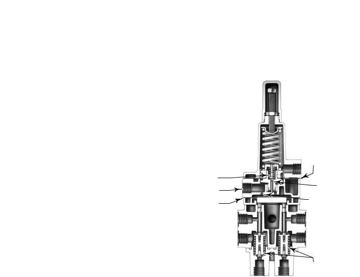
In normal operation, supply pressure loads the upper diaphragm (see figure 3) of the unit. The valve plug spring keeps the exhaust port closed. Supply pressure also loads the lower diaphragm through the restriction, causing the plug assemblies to move down and isolate ports C and F while connecting port A to B and port D to E.
Normal actuator control pressure flows from the control device to the top of the cylinder through ports A and B and to the bottom of the cylinder through ports D and E. A volume tank is charged to maximum supply pressure through a check valve in order to retain maximum supply pressure in the volume tank if supply pressure drops.
When supply pressure falls below the trip point pressure in the fail down mode (see figure 4), the exhaust port opens, venting the supply pressure that is loading the lower diaphragm. This causes the upper ports of the plug assemblies to close and shut off normal pressure flow from the control device to the actuator.
Volume tank pressure then flows through ports C and B to the top of the actuator cylinder, while pressure in the bottom of the actuator cylinder is vented through ports E and F. The pressure imbalance created forces the actuator piston down.
Figure 3. Simplified Sectional View of Trip Valve
|
UPPER |
|
|
DIAPHRAGM |
|
VALVE |
|
|
PLUG SPRING |
EXHAUST |
|
SUPPLY |
PORT |
|
|
||
CONNECTION |
RESTRICTION |
|
LOWER |
||
|
||
DIAPHRAGM |
|
|
PORT D |
PORT A |
|
PORT E |
PORT B |
PLUG
ASSEMBLIES
PORT F |
PORT C |
W4303 1
When supply pressure is restored, it loads the upper and lower diaphragms, causing the trip valve to reset. The exhaust port closes. The upper ports of the plug assemblies open, and the lower ports close. Normal actuator control pressure flow from the control device is restored through ports A and B and ports D and E. The check valve opens and recharges the volume tank to the maximum supply pressure.
4
 Loading...