


Fisher 377
www.Fisher.com
Fisher
r
377 Trip Valve
Contents
Introduction 1.................................
Scope of Manual 1.............................
Description 1.................................
Specifications 2...............................
Educational Services 2.........................
Installation 4..................................
Supply Pressure Requirements 6.................
Operating Information 8.........................
Calibration 8.................................
Principle of Operation 9.........................
377D Trip Valve 9.............................
377L Trip Valve 10.............................
377U Trip Valve 11............................
Maintenance 12................................
Periodic Operational Check 13...................
Trip Valve Part Replacement Procedures 13........
Replacing Diaphragms and Valve Plug Parts 13.....
Replacing Stem/Plug Assembly Parts 14...........
Parts Ordering 15...............................
Parts Kits 15...................................
Parts List 15...................................
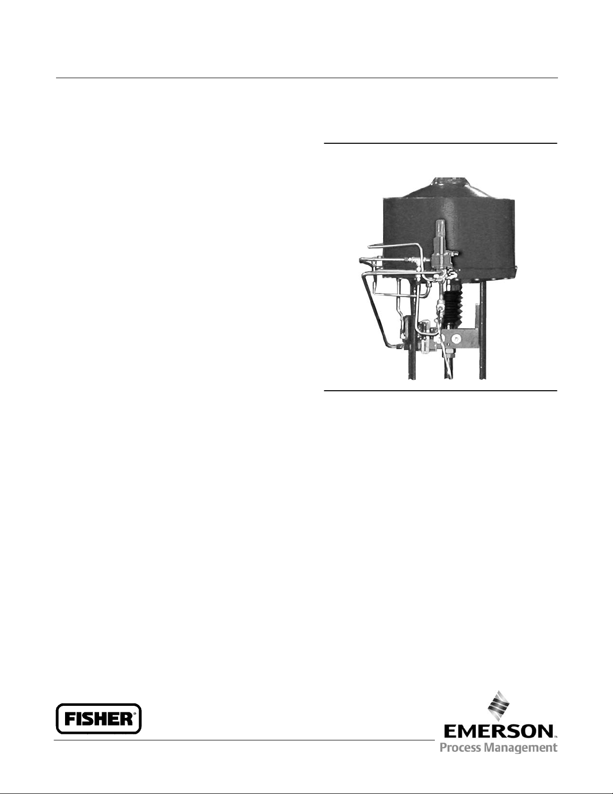
Figure 1. Fisher 377 Trip Valve Mounted on Size 130
585C Actuator
W8435‐1
Introduction
Scope of Manual
This instruction manual provides installation, operation, maintenance, and parts information for the Fisher 377 trip
valve. Refer to separate instruction manuals for information regarding the control valve, actuator, and accessories.
Do not install, operate, or maintain a 377 trip valve without being fully trained and qualified in valve, actuator and
accessory installation, operation, and maintenance. To avoid personal injury or property damage, it is important to
carefully read, understand, and follow all of the contents of this manual, including all safety cautions and warnings. If
you have any questions regarding these instructions contact your Emerson Process Management sales office before
proceeding.
Description
377 pressure‐sensing trip valves, shown in figures 1, 2, and 3, are for control applications where a specific
valve/actuator action is required when supply pressure falls below a specific point. When supply pressure falls below
the trip point, the trip valve cause the actuator to fail up, lock in the last position, or fail down. When the supply
pressure rises above the trip point, the 377 trip valve automatically resets, allowing the system to return to normal
operation. The trip valve can be top‐mounted on a manifold, yoke‐mounted, or bracket‐mounted to match the
application requirements. 377 trip valves are used with all types of piston actuators.
Instruction Manual
D200319X012
377 Trip Valve
July 2014
Instruction Manual
D200319X012
377 Trip Valve
July 2014
2
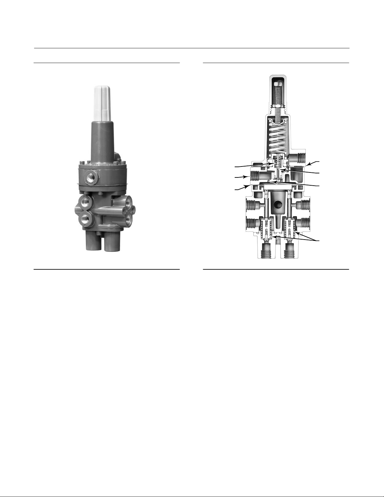
Figure 2. Typical Fisher 377 Trip Valve
W4292-1
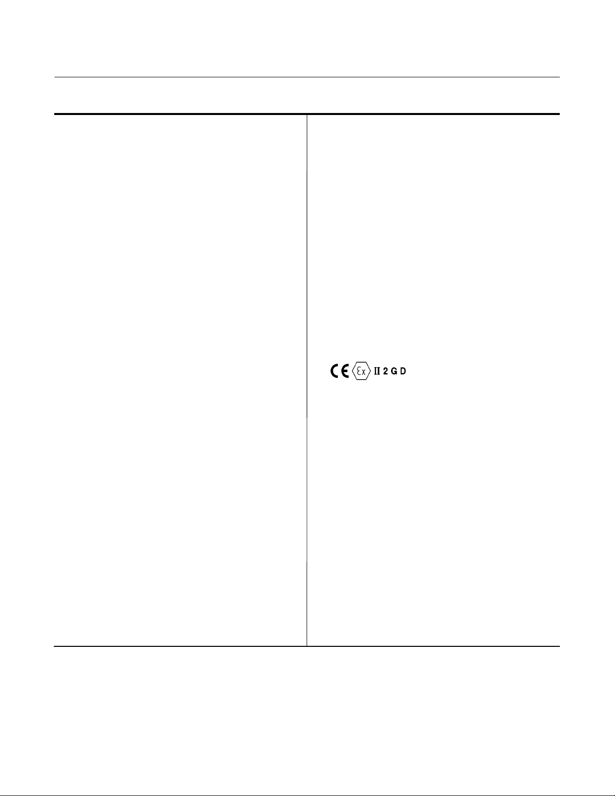
Figure 3. Simplified Sectional View of Trip Valve
UPPER
DIAPHRAGM
EXHAUST
PORT
RESTRICTION
PORT A
PORT B
PORT D
PORT E
PLUG
ASSEMBLIES
PORT F PORT C
VALVE
PLUG SPRING
SUPPLY
CONNECTION
LOWER
DIAPHRAGM
W4303‐1
Specifications
Specifications for 377 trip valves are given in table 1.
Educational Services
For information on available courses for 377 trip valves, as well as a variety of other products, contact:
Emerson Process Management
Educational Services, Registration
Phone: +1- 641-754-3771 or +1-800-338-8158
e‐mail: education@emerson.com
http://www.emersonprocess.com/education
Instruction Manual
D200319X012
377 Trip Valve
July 2014
3
Table 1. Specifications
Available Configurations
377 Trip Valve: Includes check valve, but no volume
tank: user configured for locking position. For field
use or replacement.
When supply pressure falls below the trip point,
377D Trip Valve: Fails actuator piston down. Includes
check valve and volume tank.
377L Trip Valve: Locks actuator piston in the last
position.
377U Trip Valve: Fails actuator piston up. Includes
check valve and volume tank.
377CW Trip Valve: Fails fully clockwise to close valve.
Requires check valve and volume tank. Trip valve
moves piston to either up/down position and requires
actuator configuration for actual clockwise
movement.
377CCW Trip Valve: Fails fully counterclockwise to
close valve. Requires check valve and volume tank.
Trip valve moves piston to either up/down position
and requires actuator configuration for actual
counterclockwise movement.
All 377 Trip Valves can be converted to any of the
above fail modes with minor hookup changes
Allowable Supply Pressure for Trip Valve
(1)
Maximum: 10.3 bar (150 psig)
Minimum: 3.8 bar (55 psig)
Outlet Pressure
Normal Operation: Pressure from control device
Fail‐Up or Fail‐Down Mode: Maximum volume tank
pressure
Lock‐In‐Last‐Position: Respective cylinder pressure
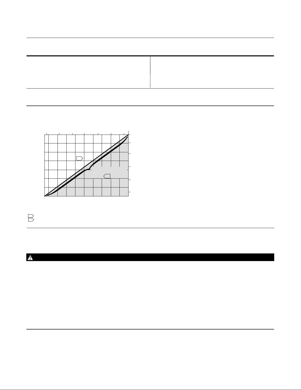
Trip Point
(2)
Adjustable from a minimum of 2.8 bar (40 psig) to a
maximum of 72 percent of supply pressure;
see figure 4
Reset: 12.5 to 33 percent above adjusted trip point
Flow Coefficients (C
v
)
(3)
Depends on flow path (shown in figure 3) as follows:
Port A to Port B and Port D to Port E: 0.5
Port B to Port C and Port E to Port F: 0.6
Pressure Connections
1/4 NPT internal
Temperature Capabilities
(1)
Nitrile Diaphragms and O‐Rings: -40 to 82_C
(-40 to 180_F)
Fluorocarbon Diaphragms and O‐Rings: -18 to 104_C
(0 to 220_F)
Volume Tank Maximum Internal Working Pressure
(for 377D, 377U, 377CW and 377CCW trip valves)
Standard: 10.3 bar (150 psig) for non‐ASME approved
applications. See note on page 7.
ASME Approved Applications: Rated 10.3 bar (150
psig), maximum; 9.3 bar (135 psig), recommended.
See note on page 7.
Hazardous Area Classification
Complies with the requirements of ATEX Group II
Category 2 Gas and Dust
377 SST
Safety Instrumented System Classification
SIL 3 capable - certified by exida Consulting LLC
Mounting
Top‐Mounted: Manifold‐mounted between a Fisher
3570 positioner and 480 actuator (manifolds cannot
be supplied with Fisher 585C, 685, 1061, 1066, and
1069 piston actuators)
Side‐Mounted: Yoke‐mounted or bracket‐mounted
for use with a FIELDVUE™ DVC6200, DVC6200f,
DVC6200p, DVC6000 or DVC6000f digital valve
controller
Approximate Weight
Trip Valve
Aluminum: 0.95 kg (2.1 pounds)
SST: 2.31 kg (5.1 pounds)
Mounting Manifold: 0.5 kg (1.2 pounds)
Volume Tank: Varies between 5.4 and 363 kg (12 and
800 pounds) depending on size
-continued-
Instruction Manual
D200319X012
377 Trip Valve
July 2014
4
Table 1. Specifications (continued)
Declaration of SEP
Fisher Controls International LLC declares this
product to be in compliance with Article 3 paragraph
3 of the Pressure Equipment Directive (PED) 97 / 23 /
EC. It was designed and manufactured in accordance
with Sound Engineering Practice (SEP) and cannot
bear the CE marking related to PED compliance.
However, the product may bear the CE marking to
indicate compliance with other applicable European
Community Directives.
1. The pressure/temperature limits in this document and any applicable standard or code limitation should not be exceeded.
2. If the trip point is not specified, the trip point is factory set at 72 percent of supply pressure or 2.8 bar (40 psig), whichever is higher.
3. Values represent nominal C
v
measures for each port pair using a trip valve/actuator combination.
Figure 4. Maximum Trip Point Settings
10.3
45 67 8 910
110
100
90
80
70
60
50
40
7.6
7
6
5
4
3
1501401301201101009080706055
NOTES:
1 TRIP POINT MAY BE SET TO ANY VALUE BETWEEN 2.8 BAR (40 PSIG) AND THE MAXIMUM TRIP POINT LINE.
2 RESET OCCURS AT 12.5 TO 33 PERCENT ABOVE ADJUSTED TRIP POINT.
TRIP POINT, PSIG
TRIP POINT, BAR
SUPPLY PRESSURE, BAR
SUPPLY PRESSURE, PSIG
A2779‐2
MAXIMUM TRIP POINT
SETTING TO ENSURE
RESET
2
1
Installation
WARNING
Avoid personal injury from sudden release of process pressure. Before mounting the controller:
D Always wear protective clothing, gloves, and eyewear when performing any installation operations to avoid personal
injury.
D Overpressuring any system component could result in personal injury or property damage due to fire and explosion
caused by venting or leakage of the supply medium. To avoid such injury or damage, provide suitable pressure‐relief or
pressure‐limiting devices if the supply pressure is capable of exceeding the maximum allowable pressure of the system
component.
D Check with your process or safety engineer for any additional measures that must be taken to protect against process
media.
D If installing into an existing application, also refer to the WARNING at the beginning of the Maintenance section in this
instruction manual.
The 377 trip valve is normally ordered as part of a control valve assembly. Follow the procedure in the appropriate
valve body and actuator instruction manual when installing the control valve in the piping.
Instruction Manual
D200319X012
377 Trip Valve
July 2014
5
If the 377 trip valve is shipped separately from the control valve assembly, the installation procedure depends upon
the type of actuator and accessory equipment required for the individual control valve system. Install any accessory
equipment in the control valve system so that the overall functioning of the specified trip valve pressure line
connections is not disrupted. Figures 7, 8, and 9 are schematics showing the pressure line connections for each of the
three possible fail‐mode configurations of the trip valve.
CAUTION
377 trip valves are leak tested to ensure that the intended actuator fail mode is maintained upon loss of supply pressure.
Control system accessories, such as volume boosters with hard seats, compromise the integrity of the entire system due to
leakage. Therefore, using control system accessories, such as volume boosters, between the trip valve and the actuator is
not recommended. If this cannot be avoided and a volume booster is required, a volume booster designed for tight shutoff,
such as the Fisher 2625, provides a higher probability of control system integrity. Refer to figures 5 and 6 for proper
installation of 377 trip valves with 2625 volume boosters.
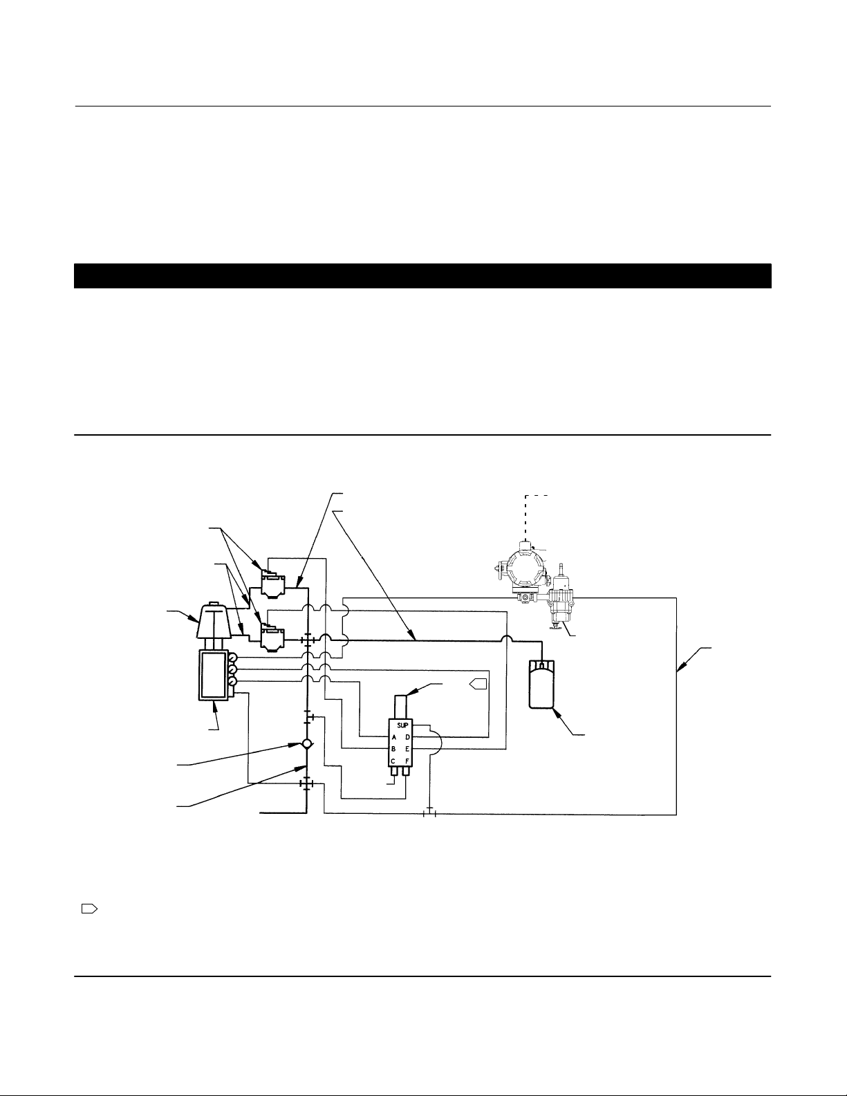
Figure 5. Fisher 2625 Volume Booster used with 377U or 377D Trip Valve
2625
1/2 O.D. TUBING
PISTON
ACTUATOR
POSITIONER
3/4 NPT
CHECK VALVE
3/4 NPT OR
1/2 NPT PIPING
SUPPLY
377U
3/8 O.D.
TUBING
TYPICAL
1
NOTES:
1 THE HOOK UP OF PORT C AND F ARE REVERSED FOR 377D.
2. 3/4 NPT CHECK VALVE, 1/2 OR 3/4 NPT PIPING, AND 1/2‐INCH (OUTSIDE DIAMETER) COIL TUBING FOR THE VOLUME TANK ARE REQUIRED.
3. THE SUPPLY PRESSURE REGULATOR SPECIFIED MUST HAVE ADEQUATE CAPACITY FOR 2625 BOOSTERS. ALSO, IF THE 2625 BOOSTER IS TO BE NIPPLE MOUNTED, THE BOOSTER MUST BE
MOUNTED TO A 1/2 NPT OR LARGER CYLINDER CONNECTION. SOME SMALLER CYLINDERS CANNOT BE TAPPED THIS LARGE; CONTACT YOUR EMERSON PROCESS MANAGEMENT SALES OFFICE
FOR AVAILABILITY ON SPECIFIC TYPES AND SIZES.
3/4 NPT OR
1/2 NPT PIPING
E1570
1/2 O.D. COIL VOLUME
TANK TUBING
VOLUME
TANK
VENT
FISHER i2P-100/
67CFR
INPUT SIGNAL
Instruction Manual
D200319X012
377 Trip Valve
July 2014
6
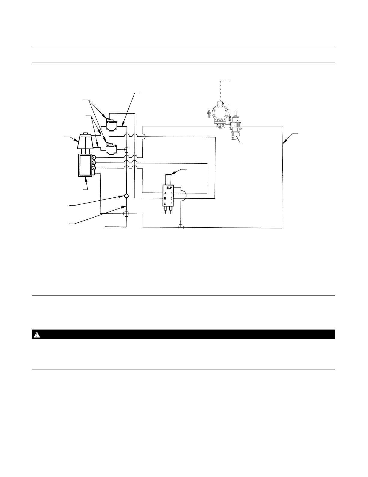
Figure 6. Fisher 2625 Volume Booster used with 377L Trip Valve
2625
1/2 O.D. TUBING
PISTON
ACTUATOR
POSITIONER
3/4 NPT
CHECK VALVE
3/4 NPT OR
1/2 NPT PIPING
SUPPLY
377L
i2P-100/67CFR
3/8 O.D.
TUBING
TYPICAL
NOTES:
1. 3/4 NPT CHECK VALVE AND 1/2 OR 3/4 NPT PIPING ARE REQUIRED.
2. THE SUPPLY PRESSURE REGULATOR SPECIFIED MUST HAVE ADEQUATE CAPACITY FOR 2625 BOOSTERS. ALSO, IF THE 2625 BOOSTER IS TO BE NIPPLE MOUNTED, THE BOOSTER MUST
BE MOUNTED TO A 1/2 NPT OR LARGER CYLINDER CONNECTION. SOME SMALLER CYLINDERS CANNOT BE TAPPED THIS LARGE; CONTACT YOUR EMERSON PROCESS MANAGEMENT
SALES OFFICE FOR AVAILABILITY ON SPECIFIC TYPES AND SIZES.
3/4 NPT OR
1/2 NPT PIPING
E1571
INPUT SIGNAL
Supply Pressure Requirements
WARNING
Severe personal injury or property damage may occur if the instrument air supply is not clean, dry, and oil free. While use
and regular maintenance of of a filter that removes particles larger than 40 micrometers in diameter will suffice in most
applications, check with an Emerson Process Management field office and instrument industry air quality standards for use
with corrosive gas or if you are unsure about the proper amount or method of air filtration or filter maintenance.
A supply regulator, if used, must have a flow capacity greater than the required combined capacity of the trip valve and
actuator. In order to ensure proper selection of a supply regulator, be sure the C
v
value of the regulator is greater than
the appropriate flow path C
v
value listed in table 1 for the trip valve. A regulator with insufficient capacity may allow
supply pressure to droop, which can cause the trip valve to trip again and begin a trip‐reset cycle. An example of an
appropriate supply regulator to use with a 377 trip valve is a 64 regulator; its capacity is usually great enough to meet
the demands of most trip valve/actuator combinations. Determine the requirements of your trip valve/actuator
combination for proper selection of a supply regulator.
 Loading...