


ZCV910

Typical installations 2
Components of system 3
Seven Step Installation
Step #1: Choose your system 3
Step #2: Plan number of inlets 4
Step #3: Plan placement of inlets 4
Step #4: Plan tubing installation 5
Step #5: Install inlet valves
Existing home 5
New construction 8
Step #6: Install tubing 9
Step #7: Install power unit 10
Safety warnings 12
Index
MAIN FLOOR
UPPER LEVEL
LOWER LEVEL GARAGE
MAIN FLOOR
CRAWLSPACE
BASEMENT
UPPER LEVEL
GARAGE
MAIN FLOOR
BASEMENT
GARAGE1
3
3
BASEMENT
2
1
1
4
4
2
3
1
3
2
MAIN FLOOR GARAGE
1
33
CRAWLSPACE
UPPER LEVEL
CRAWLSPACE BASEMENT
MAIN FLOOR
GARAGE
LOWER LEVEL
2
1
5
2
3
4
UPPER LEVEL
1
4
LOWER LEVEL
MAIN FLOOR
GARAGE
CRAWLSPACE
2
3
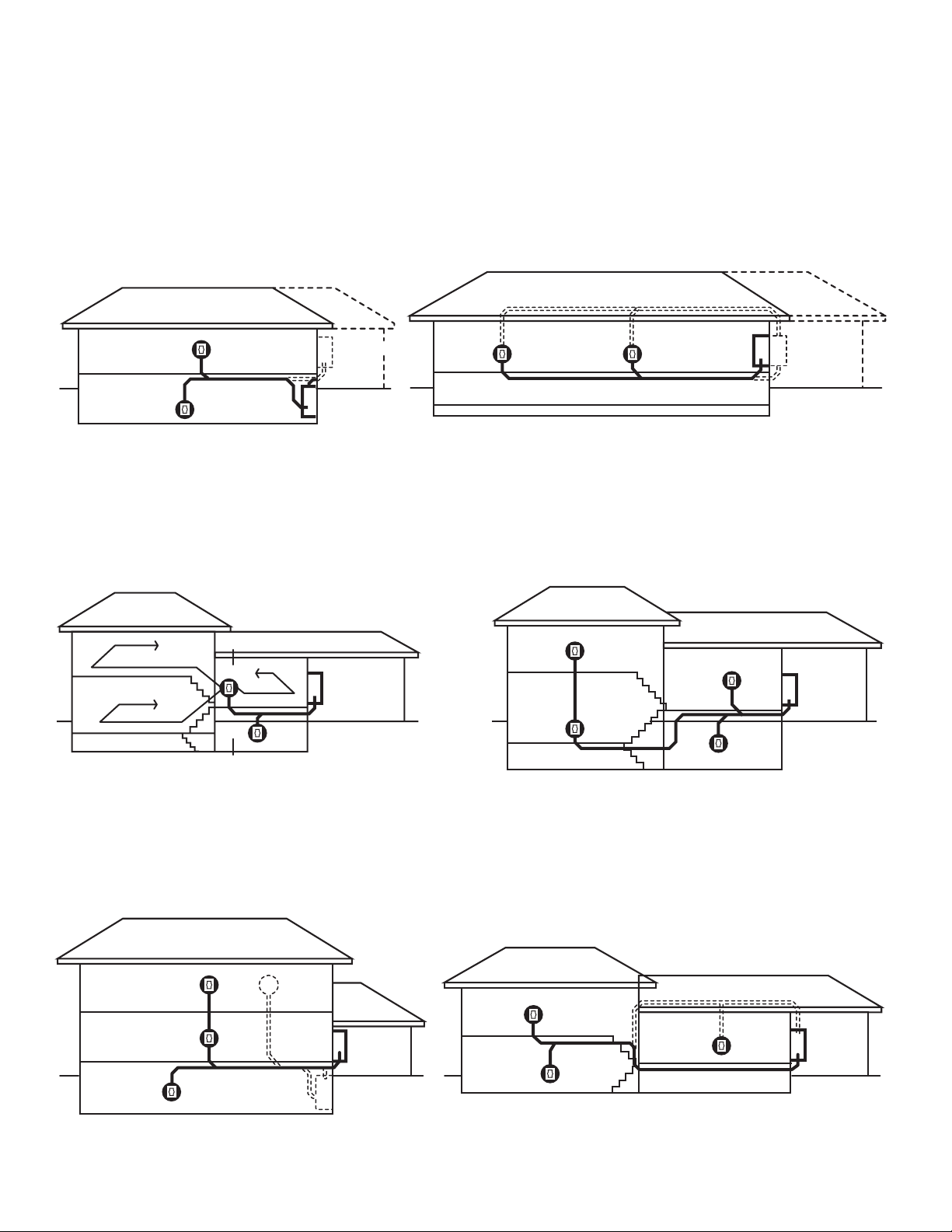
Typical Central Vacuum System Installations
Ranch-style bungalow
Single story on slab/crawlspace
4-level split Large 4-level split
Two-story
Large 3-level split
2
Seven Step Installation
Congratulations on the purchase of your new
central vacuum system. It will make cleaning your
home easier and improve indoor air quality. The
system typically can be installed in virtually any home
with no costly alterations and very little mess. This
guide will show how to install your central vacuum
system in your home in just seven steps.
Before you begin installation, read this guide. Also
review local building codes so your installation
complies with them.
Components of a central vacuum system
installation.
The Power Unit/Dust Collection
Receptacle is usually mounted in
the garage, basement, utility or
storage room to remove dust and
allergens from living areas.
Tubing & Fittings: Dust and dirt are
carried through tubing from “inlet
valves” to the power unit. Note:
ASTM tubing and fi ttings are
specifi cally designed for your
central vacuum system. Other
types of tubing, like plumbing pipe,
are different sizes and will not fi t.
Inlet valves: Installed in the wall or
fl oor, each inlet valve connects the
powerhead and fl exible cleaning
hose to the tubing in your home.
Installation Step 1: Choose
your system.
You’ve already completed step number one...you’ve
purchased your powerful new system. Next, inventory
the component parts that arrived with your central
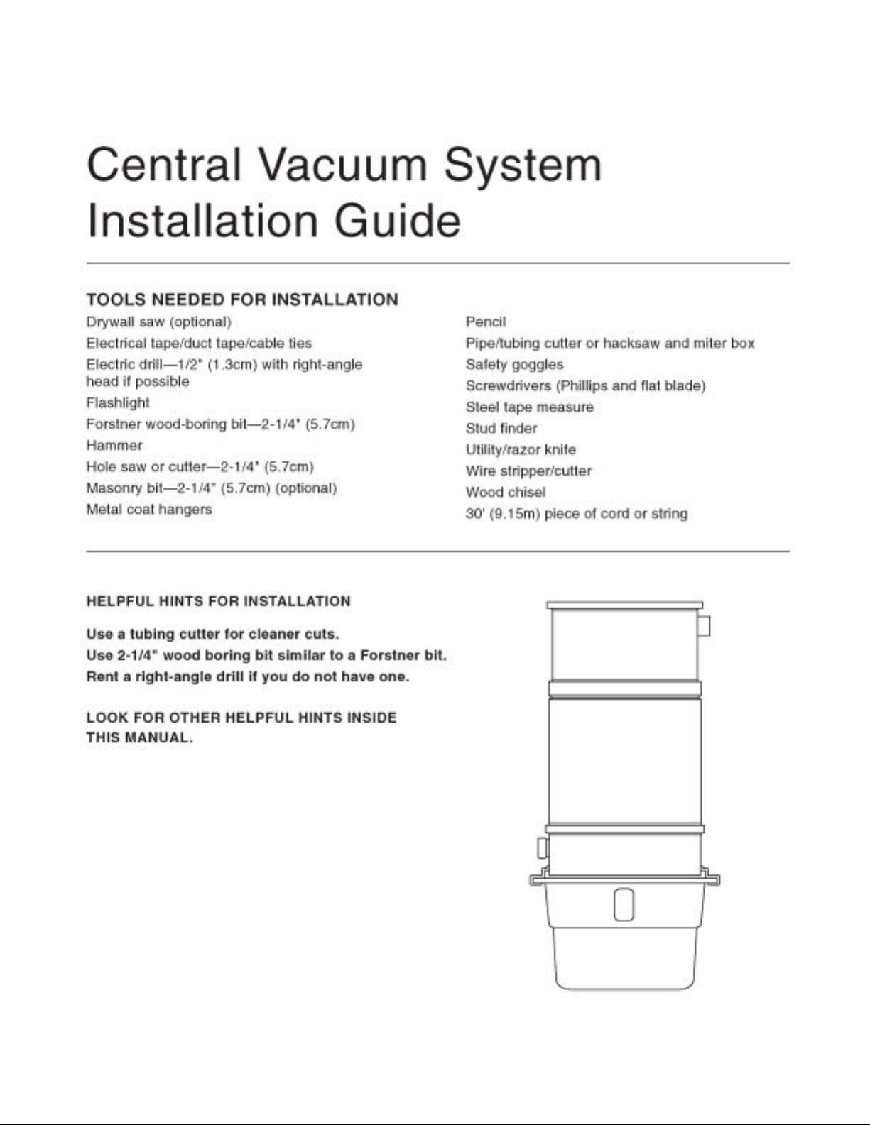
vacuum system kit and assemble the tools you will need.
(See front cover.)
Inventory all the parts.
Lay out the parts so you know you have them all
and what each is called. A three-inlet valve system
typically includes:
80' low-voltage wire
3 mounting brackets
6 nail guards
3 plaster guards
1-1/4 pint solvent sealer
6 45 degree elbows
9 90 degree sweep elbows
2 90 degree sweep tees
6 stop couplers
3 90 degree dual elbows
6 hanger clamps
6 wire nuts
3 fl oor mounting adapters
*Inlet covers sold separately
3
Installation Step 2: Decide
how many inlets you will need.
To make sure your central vacuum system reaches
every room throughout the house, you must fi rst
determine the number of inlets you will need and
where to place them. One inlet valve can serve
700-800 square feet (63-72 sq m). Use only interior
walls if possible, so you won’t have to deal with
insulation typically found in exterior walls.
Installation Step 3: Decide
where to place inlets.
Good locations are centrally located in hallways or
closet walls and/or doorways. Do not place inlets
behind doors or furniture.
Existing home: The inlet valve must be within 6 feet
(1.83m) of an electrical outlet to provide power to the
powerhead. A switch on the handle sends a signal
through “low-voltage” (24 volt) wiring to turn the power
unit on and off.
New construction: If your home is under construction,
you should consider using “electrifi ed” inlet valves.
Electrifi ed valves have low-voltage and household
wiring connections built in, so there’s no need for
a nearby electrical outlet. Inlet valves should be
installed before drywall is hung. Installation must
be coordinated with an electrician to hook up the
electrical line after the tubing has been installed
(electrifi ed valves sold separately).
Choosing the right spot for the
inlet valve.
Use a stud fi nder, or sound out the wall, to make sure
the site for the inlet valve is between the studs and
that the space is open behind the wall board. Also
check the other side of the wall to make sure it’s clear
of obstructions such as utilities and outlets. Caution:
Do not install an inlet behind a door or in a wall
that has a pocket door. Then have a helper hold the
end of the hose at the proposed site for the inlet valve
and take the other end and walk around the room(s).
If you have no helper, use a piece of cord or string
that is 30 feet (9.15m) long—the length of the hose.
You want to be able to reach everywhere from fl oor to
ceiling even with furniture in the way. You may have
to choose a different location or add another inlet to
cover the entire fl oor. Remember, one inlet usually lets
you cover about 700-800 square feet (63-72 sq m).
Repeat this on each fl oor of your home.
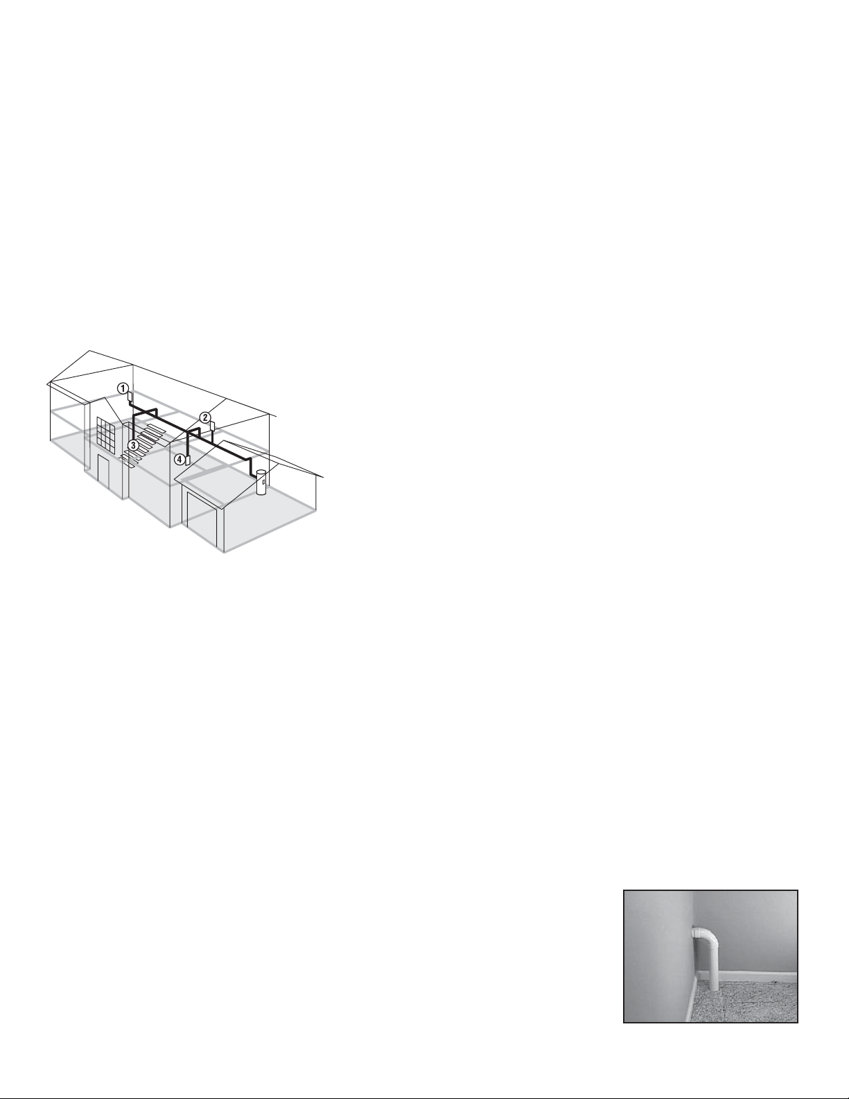
What about installing inlet valves
upstairs?
Because there are fi nished walls above and below the
second-fl oor sole plate, installing inlet valves upstairs
can take a little more ingenuity. There are several
options: Place an inlet outside a closet wall and then
run the tubing through the wall and through the inside
of the closet and down (see Fig. 03, Page 07).
Another option is to run the tubing up into the attic
then across and down to the inlet. Yet another
solution is to install the upstairs inlet valve directly
into the fl oor. Note: Although plastic inlet valves
are acceptable as long as they’re installed next
to the wall where no one will step on them, metal
fl oor inlets provide added durability. Hint: Do not
install fl oor inlets where furniture will be.
To run tubing through a
closet, mount the inlet
outside the closet and
run tubing into the closet
and down through the
closet fl oor.
4
 Loading...